- Table of Contents
-
- 05-Layer 3—IP Routing Configuration Guide
- 00-Preface
- 01-Basic IP routing configuration
- 02-Static routing configuration
- 03-RIP configuration
- 04-OSPF configuration
- 05-Policy-based routing configuration
- 06-IPv6 static routing configuration
- 07-RIPng configuration
- 08-OSPFv3 configuration
- 09-IPv6 policy-based routing configuration
- 10-Routing policy configuration
- Related Documents
-
| Title | Size | Download |
|---|---|---|
| 10-Routing policy configuration | 109.25 KB |
Implementation of a routing policy
Routing policy tasks at a glance
Configuring an IPv4 prefix list
Configuring an IPv6 prefix list
Configuring the continue clause
Display and maintenance commands for routing policies
Routing policy configuration examples
Example: Configuring a routing policy for redistributing static routes to RIP
Example: Configuring a routing policy for IPv6 route redistribution
Configuring routing policies
About routing policies
Routing policies control routing paths by filtering and modifying routing information.
Routing policies can filter advertised, received, and redistributed routes, and modify attributes for specific routes.
Implementation of a routing policy
To configure a routing policy:
1. Configure filters based on route attributes.
2. Create a routing policy and apply filters to the routing policy.
Filters
Routing policies can use the following filters to match routes.
ACL
An ACL can match the destination or next hop of routes.
For more information about ACLs, see ACL and QoS Configuration Guide.
IP prefix list
An IP prefix list matches the destination address of routes.
An IP prefix list can contain multiple items that specify prefix ranges. Each destination IP address prefix of a route is compared with these items in ascending order of their index numbers. A prefix matches the IP prefix list if it matches one item in the list.
Routing policy
A routing policy can contain multiple nodes, which are in a logical OR relationship. A node with a smaller number is matched first. A route matches the routing policy if it matches one node (except the node configured with the continue clause) in the routing policy.
Each node has a match mode of permit or deny.
· permit—Specifies the permit match mode for a routing policy node. If a route meets all the if-match clauses of the node, it is handled by the apply clauses of the node. The route is not compared with the next node unless the continue clause is configured. If a route does not meet all the if-match clauses of the node, it is compared with the next node.
· deny—Specifies the deny match mode for a routing policy node. The apply and continue clauses of a deny node are never executed. If a route meets all the if-match clauses of the node, it is denied without being compared with the next node. If a route does not meet all the if-match clauses of the node, it is compared with the next node.
A node can contain a set of if-match, apply, and continue clauses.
· if-match clauses—Specify the match criteria that match the attributes of routes. The if-match clauses are in a logical AND relationship. A route must meet all the if-match clauses to match the node.
· apply clauses—Specify the actions to be taken on permitted routes, such as modifying a route attribute.
· continue clause—Specifies the next node. A route that matches the current node (permit node) must match the specified next node in the same routing policy. The continue clause combines the if-match and apply clauses of the two nodes to improve flexibility of the routing policy.
Follow these guidelines when you configure if-match, apply, and continue clauses:
· If you only want to filter routes, do not configure apply clauses.
· If you do not configure any if-match clauses for a permit node, the node will permit all routes.
· Configure a permit node containing no if-match or apply clauses following multiple deny nodes to allow unmatched routes to pass.
Routing policy tasks at a glance
To configure a routing policy, perform the following tasks:
1. (Optional.) Configure filters:
? Configuring an IPv4 prefix list
? Configuring an IPv6 prefix list
2. Configuring a routing policy:
b. Configuring if-match clauses
d. Configuring the continue clause
Configuring an IPv4 prefix list
Restrictions and guidelines
If all the items are set to deny mode, no routes can pass the IPv4 prefix list. To permit unmatched IPv4 routes, you must configure the permit 0.0.0.0 0 less-equal 32 item following multiple deny items.
Procedure
1. Enter system view.
system-view
2. Configure an IPv4 prefix list.
ip prefix-list prefix-list-name [ index index-number ] { deny | permit } ip-address mask-length [ greater-equal min-mask-length ] [ less-equal max-mask-length ]
Configuring an IPv6 prefix list
Restrictions and guidelines
If all items are set to deny mode, no routes can pass the IPv6 prefix list. To permit unmatched IPv6 routes, you must configure the permit :: 0 less-equal 128 item following multiple deny items.
Procedure
1. Enter system view.
system-view
2. Configure an IPv6 prefix list.
ipv6 prefix-list prefix-list-name [ index index-number ] { deny | permit } ipv6-address { inverse inverse-prefix-length | prefix-length [ greater-equal min-prefix-length ] [ less-equal max-prefix-length ] }
Configuring a routing policy
Creating a routing policy
About creating a routing policy
A routing policy must have a minimum of one permit node. If all the nodes are in deny mode, no routes can pass the routing policy.
Procedure
1. Enter system view.
system-view
2. Create a routing policy and a node, and enter routing policy node view.
route-policy route-policy-name { deny | permit } node node-number
Configuring if-match clauses
About if-match clause configuration
You can either specify no if-match clauses or multiple if-match clauses for a routing policy node. If no if-match clause is specified for a permit node, all routes can pass the node. If no if-match clause is specified for a deny node, no routes can pass the node.
Restrictions and guidelines
When you configure if-match clauses, follow these restrictions and guidelines:
· The if-match clauses of a routing policy node have a logical AND relationship. A route must meet all if-match clauses before it can be executed by the apply clauses of the node. If an if-match command exceeds the maximum length, multiple if-match clauses of the same type are generated. These clauses have a logical OR relationship. A route only needs to meet one of them.
· All IPv4 routes match a node if the if-match clauses of the node use only IPv6 ACLs. All IPv6 routes match a node if the if-match clauses of the node use only IPv4 ACLs.
· If the ACL used by an if-match clause does not exist, the clause is always matched. If no rules of the specified ACL are matched or the match rules are inactive, the clause is not matched.
· If the prefix list, community list, or extended community list used by an if-match clause does not exist, the clause is always matched. If no rules of the specified prefix list, community list, or extended community list are matched, the clause is not matched.
Procedure
1. Enter system view.
system-view
2. Enter routing policy node view.
route-policy route-policy-name { deny | permit } node node-number
3. Match routes whose destination, next hop, or source address matches an ACL or prefix list.
IPv4:
if-match ip { address | next-hop | route-source } { acl ipv4-acl-number | prefix-list prefix-list-name }
IPv6:
if-match ipv6 { address | next-hop | route-source } { acl ipv6-acl-number | prefix-list prefix-list-name }
By default, no ACL or prefix list match criterion is configured.
The ACL specified in an if-match clause must be a non-VPN ACL.
4. Configure route match criteria.
? Match routes having the specified cost.
if-match cost cost-value
? Match routes having the specified output interface.
if-match interface { interface-type interface-number }&<1-16>
? Match routes having the specified route type.
if-match route-type { external-type1 | external-type1or2 | external-type2 | internal | nssa-external-type1 | nssa-external-type1or2 | nssa-external-type2 } *
? Match IGP routes having the specified tag value.
if-match tag tag-value
By default, no route match criteria are configured.
Configuring apply clauses
1. Enter system view.
system-view
2. Enter routing policy node view.
route-policy route-policy-name { deny | permit } node node-number
3. Configure the route cost and cost type.
? Set a cost for routes.
apply cost [ + | - ] cost-value
By default, no cost is set for routes.
? Set a cost type for routes.
apply cost-type { type-1 | type-2 }
By default, no cost type is set for routes.
4. Set the next hop for routes.
IPv4:
apply ip-address next-hop ip-address [ public ]
IPv6:
apply ipv6 next-hop ipv6-address
By default, no next hop is set for routes.
The configuration does not apply to redistributed routes.
5. Configure route priorities.
? Set an IP precedence for matching routes.
apply ip-precedence { value | clear }
By default, no IP precedence is set.
? Set a preference.
apply preference preference
By default, no preference is set.
? Set a prefix priority.
apply prefix-priority { critical | high | medium }
By default, the prefix priority is low.
6. Set a tag value for IGP routes.
apply tag tag-value
By default, no tag value is set for IGP routes.
7. Set a backup link for fast reroute (FRR).
IPv4:
apply fast-reroute { backup-interface interface-type interface-number [ backup-nexthop ip-address ] | backup-nexthop ip-address }
IPv6:
apply ipv6 fast-reroute { backup-interface interface-type interface-number [ backup-nexthop ipv6-address ] | backup-nexthop ipv6-address }
By default, no backup link is set for FRR.
Configuring the continue clause
Restrictions and guidelines
When you configure the continue clause to combine multiple nodes, follow these restrictions and guidelines:
· If you configure an apply clause that sets different attribute values on all the nodes, the apply clause of the node configured most recently takes effect.
· If you configure the following apply clauses on all the nodes, the apply clause of each node takes effect:
? apply as-path without the replace keyword.
? apply cost with the + or – keyword.
? apply community with the additive keyword.
? apply extcommunity with the additive keyword.
· The apply comm-list delete clause configured on the current node cannot delete the community attributes set by the apply community clauses of the preceding nodes.
Procedure
1. Enter system view.
system-view
2. Enter routing policy node view.
route-policy route-policy-name { deny | permit } node node-number
3. Specify the next node to be matched.
continue [ node-number ]
By default, no continue clause is configured.
The specified next node must have a larger number than the current node.
Display and maintenance commands for routing policies
Execute display commands in any view and reset commands in user view.
|
Task |
Command |
|
Display IPv4 prefix list statistics. |
display ip prefix-list [ name prefix-list-name ] |
|
Display IPv6 prefix list statistics. |
display ipv6 prefix-list [ name prefix-list-name ] |
|
Display routing policy information. |
display route-policy [ name route-policy-name ] |
|
Clear IPv4 prefix list statistics. |
reset ip prefix-list [ prefix-list-name ] |
|
Clear IPv6 prefix list statistics. |
reset ipv6 prefix-list [ prefix-list-name ] |
Routing policy configuration examples
Example: Configuring a routing policy for redistributing static routes to RIP
Network configuration
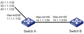
As shown in Figure 1, Switch A exchanges routing information with Switch B by using RIP.
On Switch A, configure three static routes. Use a routing policy to configure Switch B to redistribute networks 20.1.1.1/32 and 40.1.1.1/32 and block network 30.1.1.1/32.
Procedure
1. Configure Switch A:
# Configure IP addresses for interfaces VLAN-interface 100 and VLAN-interface 200.
<SwitchA> system-view
[SwitchA] interface vlan-interface 100
[SwitchA-vlan-interface100] ip address 10.1.1.1 30
[SwitchA-vlan-interface100] quit
[SwitchA] interface vlan-interface 200
[SwitchA-vlan-interface200] ip address 11.1.1.1 32
[SwitchA-vlan-interface200] quit
# Enable RIP on interface VLAN-interface 100.
[SwitchA] interface vlan-interface 100
[SwitchA-vlan-interface100] rip 1 enable
[SwitchA-vlan-interface100] quit
# Configure three static routes and set the next hop of the three routes to 11.1.1.2.
[SwitchA] ip route-static 20.1.1.1 32 11.1.1.2
[SwitchA] ip route-static 30.1.1.1 32 11.1.1.2
[SwitchA] ip route-static 40.1.1.1 32 11.1.1.2
# Configure a routing policy.
[SwitchA] ip prefix-list a index 10 permit 30.1.1.1 32
[SwitchA] route-policy static2rip deny node 0
[SwitchA-route-policy-static2rip-0] if-match ip address prefix-list a
[SwitchA-route-policy-static2rip-0] quit
[SwitchA] route-policy static2rip permit node 10
[SwitchA-route-policy-static2rip-10] quit
# Enable RIP and apply routing policy static2rip to filter redistributed static routes.
[SwitchA] rip
[SwitchA-rip-1] import-route static route-policy static2rip
2. Configure Switch B:
# Configure an IP address for interface VLAN-interface 100.
<SwitchB> system-view
[SwitchB] interface vlan-interface 100
[SwitchB-vlan-interface100] ip address 10.1.1.2 30
# Enable RIP.
[SwitchB] rip
[SwitchB-rip-1] quit
# Enable RIP on the interface.
[SwitchB] interface vlan-interface 100
[SwitchB-vlan-interface100] rip 1 enable
[SwitchB-vlan-interface100] quit
Verifying the configuration
# Display the routing table information on Switch B.
<H3C>display ip routing-table
Destinations : 14 Routes : 14
Destination/Mask Proto Pre Cost NextHop Interface
0.0.0.0/32 Direct 0 0 127.0.0.1 InLoop0
10.1.1.0/30 Direct 0 0 10.1.1.2 Vlan100
10.1.1.0/32 Direct 0 0 10.1.1.2 Vlan100
10.1.1.2/32 Direct 0 0 127.0.0.1 InLoop0
10.1.1.3/32 Direct 0 0 10.1.1.2 Vlan100
20.0.0.0/8 RIP 100 1 10.1.1.1 Vlan100
40.0.0.0/8 RIP 100 1 10.1.1.1 Vlan100
127.0.0.0/8 Direct 0 0 127.0.0.1 InLoop0
127.0.0.0/32 Direct 0 0 127.0.0.1 InLoop0
127.0.0.1/32 Direct 0 0 127.0.0.1 InLoop0
127.255.255.255/32 Direct 0 0 127.0.0.1 InLoop0
224.0.0.0/4 Direct 0 0 0.0.0.0 NULL0
224.0.0.0/24 Direct 0 0 0.0.0.0 NULL0
255.255.255.255/32 Direct 0 0 127.0.0.1 InLoop0
Example: Configuring a routing policy for IPv6 route redistribution
Network configuration
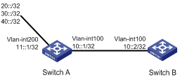
As shown in Figure 2:
· Run RIPng on Switch A and Switch B.
· Configure three static routes on Switch A.
· On Switch A, apply a routing policy to redistribute static routes 20::/32 and 40::/32 and deny route 30::/32.
Procedure
1. Configure Switch A:
# Configure IPv6 addresses for VLAN-interface 100 and VLAN-interface 200.
<SwitchA> system-view
[SwitchA] interface vlan-interface 100
[SwitchA-Vlan-interface100] ipv6 address 10::1 32
[SwitchA-Vlan-interface100] quit
[SwitchA] interface vlan-interface 200
[SwitchA-Vlan-interface200] ipv6 address 11::1 32
[SwitchA-Vlan-interface200] quit
# Enable RIPng on VLAN-interface 100.
[SwitchA] interface vlan-interface 100
[SwitchA-Vlan-interface100] ripng 1 enable
[SwitchA-Vlan-interface100] quit
# Configure three static routes with next hop 11::2, and make sure the static routes are active.
[SwitchA] ipv6 route-static 20:: 32 11::2
[SwitchA] ipv6 route-static 30:: 32 11::2
[SwitchA] ipv6 route-static 40:: 32 11::2
# Configure a routing policy.
[SwitchA] ipv6 prefix-list a index 10 permit 30:: 32
[SwitchA] route-policy static2ripng deny node 0
[SwitchA-route-policy-static2ripng-0] if-match ipv6 address prefix-list a
[SwitchA-route-policy-static2ripng-0] quit
[SwitchA] route-policy static2ripng permit node 10
[SwitchA-route-policy-static2ripng-10] quit
# Enable RIPng and apply the routing policy to static route redistribution.
[SwitchA] ripng
[SwitchA-ripng-1] import-route static route-policy static2ripng
2. Configure Switch B:
# Configure the IPv6 address for VLAN-interface 100.
<SwitchB> system-view
[SwitchB] interface vlan-interface 100
[SwitchB-Vlan-interface100] ipv6 address 10::2 32
# Enable RIPng.
[SwitchB] ripng
[SwitchB-ripng-1] quit
# Enable RIPng on VLAN-interface 100.
[SwitchB] interface vlan-interface 100
[SwitchB-Vlan-interface100] ripng 1 enable
[SwitchB-Vlan-interface100] quit
Verifying the configuration
# Display the RIPng routing table on Switch B.
[SwitchB] display ripng 1 route
Route Flags: A - Aging, S - Suppressed, G - Garbage-collect
----------------------------------------------------------------
Peer FE80::7D58:0:CA03:1 on Vlan-interface 100
Destination 20::/32,
via FE80::7D58:0:CA03:1, cost 1, tag 0, A, 8 secs
Destination 40::/32,
via FE80::7D58:0:CA03:1, cost 1, tag 0, A, 3 secs
Local route
Destination 10::/32,
via ::, cost 0, tag 0, DOF
