- Table of Contents
-
- 05-Layer 3—IP Routing Configuration Guide
- 00-Preface
- 01-Basic IP routing configuration
- 02-Static routing configuration
- 03-RIP configuration
- 04-OSPF configuration
- 05-Policy-based routing configuration
- 06-IPv6 static routing configuration
- 07-RIPng configuration
- 08-OSPFv3 configuration
- 09-IPv6 policy-based routing configuration
- 10-Routing policy configuration
- Related Documents
-
| Title | Size | Download |
|---|---|---|
| 03-RIP configuration | 368.09 KB |
Restrictions and guidelines for configuring basic RIP
Controlling RIP reception and advertisement on interfaces
Configuring an additional routing metric
Configuring RIPv2 route summarization
Disabling host route reception
Configuring received/redistributed route filtering
Configuring RIP route redistribution
Tuning and optimizing RIP networks
Enabling split horizon and poison reverse
Setting the RIP triggered update interval
Configuring the RIP packet sending rate
Setting the maximum length of RIP packets
Setting the DSCP value for outgoing RIP packets
Configuring RIP network management
Configuring single-hop echo detection (for a directly connected RIP neighbor)
Configuring single-hop echo detection (for a specific destination)
Configuring bidirectional control detection
Restrictions and guidelines for RIP FRR
Enabling zero field check for incoming RIPv1 messages
Enabling source IP address check for incoming RIP updates
Configuring RIPv2 message authentication
Display and maintenance commands for RIP
Example: Configuring basic RIP
Example: Configuring RIP route redistribution
Example: Configuring an additional metric for a RIP interface
Example: Configuring RIP to advertise a summary route
Example: Configuring BFD for RIP (single-hop echo detection for a directly connected neighbor)
Example: Configuring BFD for RIP (single hop echo detection for a specific destination)
Example: Configuring BFD for RIP (bidirectional detection in BFD control packet mode)
Configuring RIP
About RIP
Routing Information Protocol (RIP) is a distance-vector IGP suited to small-sized networks. It employs UDP to exchange route information through port 520.
RIP routing metrics
RIP uses a hop count to measure the distance to a destination. The hop count from a router to a directly connected network is 0. The hop count from a router to a directly connected router is 1. To limit convergence time, RIP restricts the value range of the metric from 0 to 15. A destination with a metric value of 16 (or greater) is considered unreachable. For this reason, RIP is not suitable for large-sized networks.
RIP route entries
RIP stores routing entries in a database. Each routing entry contains the following elements:
· Destination address—IP address of a destination host or a network.
· Next hop—IP address of the next hop.
· Egress interface—Egress interface of the route.
· Metric—Cost from the local router to the destination.
· Route time—Time elapsed since the last update. The time is reset to 0 when the routing entry is updated.
· Route tag—Used for route control. For more information, see "Configuring routing policies."
RIP operation
RIP works as follows:
1. RIP sends request messages to neighboring routers. Neighboring routers return response messages that contain their routing tables.
2. RIP uses the received responses to update the local routing table and sends triggered update messages to its neighbors. All RIP routers on the network do this to learn latest routing information.
3. RIP periodically sends the local routing table to its neighbors. After a RIP neighbor receives the message, it updates its routing table, selects optimal routes, and sends an update to other neighbors. RIP ages routes to keep only valid routes.
Routing loop prevention
RIP uses the following mechanisms to prevent routing loops:
· Counting to infinity—A destination with a metric value of 16 is considered unreachable. When a routing loop occurs, the metric value of a route will increment to 16 to avoid endless looping.
· Triggered updates—RIP immediately advertises triggered updates for topology changes to reduce the possibility of routing loops and to speed up convergence.
· Split horizon—Disables RIP from sending routes through the interface where the routes were learned to prevent routing loops and save bandwidth.
· Poison reverse—Enables RIP to set the metric of routes received from a neighbor to 16 and sends these routes back to the neighbor. The neighbor can delete such information from its routing table to prevent routing loops.
RIP versions
There are two RIP versions, RIPv1 and RIPv2.
RIPv1 is a classful routing protocol. It advertises messages only through broadcast. RIPv1 messages do not carry mask information, so RIPv1 can only recognize natural networks such as Class A, B, and C. For this reason, RIPv1 does not support discontiguous subnets.
RIPv2 is a classless routing protocol. It has the following advantages over RIPv1:
· Supports route tags to implement flexible route control through routing policies.
· Supports masks, route summarization, and CIDR.
· Supports designated next hops to select the best ones on broadcast networks.
· Supports multicasting route updates so only RIPv2 routers can receive these updates to reduce resource consumption.
· Supports plain text authentication and MD5 authentication to enhance security.
RIPv2 supports two transmission modes: broadcast and multicast. Multicast is the default mode using 224.0.0.9 as the multicast address. An interface operating in RIPv2 broadcast mode can also receive RIPv1 messages.
Protocols and standards
· RFC 1058, Routing Information Protocol
· RFC 1723, RIP Version 2 - Carrying Additional Information
· RFC 1721, RIP Version 2 Protocol Analysis
· RFC 1722, RIP Version 2 Protocol Applicability Statement
· RFC 1724, RIP Version 2 MIB Extension
· RFC 2082, RIPv2 MD5 Authentication
· RFC 2091, Triggered Extensions to RIP to Support Demand Circuits
RIP tasks at a glance
To configure RIP, perform the following tasks:
a. Enabling RIP
b. (Optional.) Controlling RIP reception and advertisement on interfaces
c. (Optional.) Configuring a RIP version
To enable RIP on a link that does not support broadcast or multicast, you must manually specify a RIP neighbor.
2. (Optional.) Configuring RIP route control
¡ Configuring an additional routing metric
¡ Configuring RIPv2 route summarization
¡ Disabling host route reception
¡ Configuring received/redistributed route filtering
¡ Setting a preference for RIP
¡ Configuring RIP route redistribution
3. (Optional.) Tuning and optimizing RIP networks
¡ Enabling split horizon and poison reverse
¡ Setting the RIP triggered update interval
¡ Configuring the RIP packet sending rate
¡ Setting the maximum length of RIP packets
¡ Setting the DSCP value for outgoing RIP packets
4. (Optional.) Configuring RIP network management
5. Enhancing RIP availability
6. (Optional.) Enhancing RIP security
¡ Enabling zero field check for incoming RIPv1 messages
¡ Enabling source IP address check for incoming RIP updates
¡ Configuring RIPv2 message authentication
Configuring basic RIP
Restrictions and guidelines for configuring basic RIP
To enable multiple RIP processes on a router, you must specify an ID for each process. A RIP process ID has only local significance. Two RIP routers having different process IDs can also exchange RIP packets.
Enabling RIP
About enabling RIP
You can enable RIP on a network and specify a wildcard mask for the network. After that, only the interface attached to the network runs RIP.
Restrictions and guidelines
If you configure RIP settings in interface view before enabling RIP, the settings do not take effect until RIP is enabled.
If a physical interface is attached to multiple networks, you cannot advertise these networks in different RIP processes.
You cannot enable multiple RIP processes on a physical interface.
The rip enable command takes precedence over the network command.
Enabling RIP on a network
1. Enter system view.
system-view
2. Enable RIP and enter RIP view.
rip [ process-id ]
By default, RIP is disabled.
3. Enable RIP on a network.
network network-address [ wildcard-mask ]
By default, RIP is disabled on a network.
The network 0.0.0.0 command can enable RIP on all interfaces in a single process, but does not apply to multiple RIP processes.
Enabling RIP on an interface
1. Enter system view.
system-view
2. Enable RIP and enter RIP view.
rip [ process-id ]
By default, RIP is disabled.
3. Return to system view.
quit
4. Enter interface view.
interface interface-type interface-number
5. Enable RIP on the interface.
rip process-id enable [ exclude-subip ]
By default, RIP is disabled on an interface.
Controlling RIP reception and advertisement on interfaces
About RIP reception and advertisement control on interfaces
You can perform this task to configure the following features:
· Suppressing an interface. The suppressed interface can receive RIP messages but cannot send RIP messages.
· Disabling an interface from sending RIP messages.
· Disabling an interface from receiving RIP messages.
Restrictions and guidelines for RIP reception and advertisement control on interfaces
An interface suppressed by using the silent-interface command can only receive RIP messages. It cannot send RIP messages. You can use the silent-interface all command to suppress all interfaces. The silent-interface command takes precedence over the rip input and rip output commands.
Suppressing an interface
1. Enter system view.
system-view
2. Enter RIP view.
rip [ process-id ]
3. Suppress an interface.
silent-interface { interface-type interface-number | all }
By default, all RIP-enabled interfaces can send RIP messages.
The suppressed interface can still receive RIP messages and respond to unicast requests containing unknown ports.
Disabling an interface from receiving RIP messages
1. Enter system view.
system-view
2. Enter interface view.
interface interface-type interface-number
3. Disable an interface from receiving RIP messages.
undo rip input
By default, a RIP-enabled interface can receive RIP messages.
Disabling an interface from sending RIP messages
1. Enter system view.
system-view
2. Enter interface view.
interface interface-type interface-number
3. Disable an interface from sending RIP messages.
undo rip output
By default, a RIP-enabled interface can send RIP messages.
Configuring a RIP version
About RIP version configuration
You can configure a global RIP version in RIP view or an interface-specific RIP version in interface view.
An interface preferentially uses the interface-specific RIP version. If no interface-specific version is specified, the interface uses the global RIP version. If neither a global nor interface-specific RIP version is configured, the interface sends RIPv1 broadcasts and can receive the following:
· RIPv1 broadcasts and unicasts.
· RIPv2 broadcasts, multicasts, and unicasts.
Procedure
1. Enter system view.
system-view
2. Specify a RIP version.
¡ Execute the following commands in sequence to specify a global RIP version:
rip [ process-id ]
version { 1 | 2 }
By default, no global version is specified. An interface sends RIPv1 broadcasts, and can receive RIPv1 broadcasts and unicasts, and RIPv2 broadcasts, multicasts, and unicasts.
¡ Execute the following commands in sequence to specify a RIP version on an interface:
interface interface-type interface-number
rip version { 1 | 2 [ broadcast | multicast ] }
By default, no interface-specific RIP version is specified. The interface sends RIPv1 broadcasts, and can receive RIPv1 broadcasts and unicasts, and RIPv2 broadcasts, multicasts, and unicasts.
Specifying a RIP neighbor
About RIP neighbors
Typically RIP messages are sent in broadcast or multicast. To enable RIP on a link that does not support broadcast or multicast, you must manually specify a RIP neighbor.
Restrictions and guidelines
As a best practice, do not use the peer ip-address command to specify a directly connected neighbor. The neighbor might receive a route update in both unicast and multicast (or broadcast) messages from the device.
Procedure
1. Enter system view.
system-view
2. Enter RIP view.
rip [ process-id ]
3. Specify a RIP neighbor.
peer ip-address
By default, RIP does not unicast updates to any peer.
4. Disable source IP address check on inbound RIP updates.
undo validate-source-address
By default, source IP address check is enabled on inbound RIP updates.
If the specified neighbor is not directly connected, disable source address check on incoming updates.
Configuring RIP route control
Configuring an additional routing metric
About additional routing metrics
An additional routing metric (hop count) can be added to the metric of an inbound or outbound RIP route.
· An outbound additional metric is added to the metric of a sent route, and it does not change the route's metric in the routing table.
· An inbound additional metric is added to the metric of a received route before the route is added into the routing table, and the route's metric is changed. If the sum of the additional metric and the original metric is greater than 16, the metric of the route is 16.
Procedure
1. Enter system view.
system-view
2. Enter interface view.
interface interface-type interface-number
3. Specify an inbound additional routing metric.
rip metricin [ route-policy route-policy-name ] value
By default, the additional metric of an inbound route is 0.
4. Specify an outbound additional routing metric.
rip metricout [ route-policy route-policy-name ] value
By default, the additional metric of an outbound route is 1.
Configuring RIPv2 route summarization
About RIPv2 route summarization
Perform this task to summarize contiguous subnets into a summary network and sends the network to neighbors. The smallest metric among all summarized routes is used as the metric of the summary route.
You can use the following methods to summarize routes in RIPv2:
· Automatic summarization—Configure RIPv2 to generate a natural network for contiguous subnets. For example, suppose there are three subnet routes 10.1.1.0/24, 10.1.2.0/24, and 10.1.3.0/24. Automatic summarization automatically creates and advertises a summary route 10.0.0.0/8 instead of the more specific routes.
· Manual summarization—Manually configure a summary route. RIPv2 advertises the summary route rather than more specific routes. For example, suppose contiguous subnets routes 10.1.1.0/24, 10.1.2.0/24, and 10.1.3.0/24 exist in the routing table. You can create a summary route 10.1.0.0/16 on GigabitEthernet 1/0/1 to advertise the summary route instead of the more specific routes. By default, natural masks are used to advertise summary routes. To manually configure a summary route on an interface, you must first disable RIPv2 automatic route summarization.
Restrictions and guidelines
To prevent loops caused by route summarization, create a black hole route by specifying interface NULL 0 as the output interface of the summary route. Packets that match the black hole route are dropped.
Enabling RIPv2 automatic route summarization
1. Enter system view.
system-view
2. Enter RIP view.
rip [ process-id ]
3. Enable RIPv2 automatic route summarization.
summary
By default, RIPv2 automatic route summarization is enabled.
If subnets in the routing table are not contiguous, disable automatic route summarization to advertise more specific routes.
Advertising a summary route
1. Enter system view.
system-view
2. Enter RIP view.
rip [ process-id ]
3. Disable RIPv2 automatic route summarization.
undo summary
By default, RIPv2 automatic route summarization is enabled.
4. Return to system view.
quit
5. Enter interface view.
interface interface-type interface-number
6. Configure a summary route.
rip summary-address ip-address { mask-length | mask }
By default, no summary route is configured.
Disabling host route reception
About disabling host route reception
This task disables RIPv2 from receiving host routes from the same network to save network resources. This feature does not apply to RIPv1.
Procedure
1. Enter system view.
system-view
2. Enter RIP view.
rip [ process-id ]
3. Disable RIP from receiving host routes.
undo host-route
By default, RIP receives host routes.
Advertising a default route
About default route advertisement
You can advertise a default route on all RIP interfaces in RIP view or on a specific RIP interface in interface view. The interface view setting takes precedence over the RIP view settings.
To disable an interface from advertising a default route, use the rip default-route no-originate command on the interface.
The router enabled to advertise a default route does not accept default routes from RIP neighbors.
Procedure
1. Enter system view.
system-view
2. Advertise a default route.
¡ Execute the following commands in sequence to configure RIP to advertise a default route:
rip [ process-id ]
default-route { only | originate } [ cost cost-value | route-policy route-policy-name ] *
By default, RIP does not advertise a default route.
¡ Execute the following commands in sequence to configure a RIP interface to advertise a default route:
interface interface-type interface-number
rip default-route { { only | originate } [ cost cost-value | route-policy route-policy-name ] * | no-originate }
By default, a RIP interface can advertise a default route if the RIP process is enabled to advertise a default route.
Configuring received/redistributed route filtering
About received/redistributed route filtering
This task allows you to create a policy to filter received or redistributed routes that match specific criteria such as an ACL or IP prefix list.
Procedure
1. Enter system view.
system-view
2. Enter RIP view.
rip [ process-id ]
3. Configure the filtering of received routes.
filter-policy { ipv4-acl-number | gateway prefix-list-name | prefix-list prefix-list-name [ gateway prefix-list-name ] } import [ interface-type interface-number ]
By default, the filtering of received routes is not configured.
This command filters received routes. Filtered routes are not installed into the routing table or advertised to neighbors.
4. Configure the filtering of redistributed routes.
filter-policy { ipv4-acl-number | prefix-list prefix-list-name } export [ protocol [ process-id ] | interface-type interface-number ]
By default, the filtering of redistributed routes is not configured.
This command filters redistributed routes, including routes redistributed with the import-route command.
Setting a preference for RIP
About setting a preference for RIP
If multiple IGPs find routes to the same destination, the route found by the IGP that has the highest priority is selected as the optimal route. Perform this task to assign a preference to RIP. The smaller the preference value, the higher the priority.
Procedure
1. Enter system view.
system-view
2. Enter RIP view.
rip [ process-id ]
3. Set a preference for RIP.
preference { preference | route-policy route-policy-name } *
The default preference for RIP is 100.
Configuring RIP route redistribution
About RIP route redistribution
Perform this task to configure RIP to redistribute routes from other routing protocols, including OSPF, static, and direct.
Procedure
1. Enter system view.
system-view
2. Enter RIP view.
rip [ process-id ]
3. Redistribute routes from another routing protocol.
¡ Redistribute direct or static routes.
import-route { direct | static } [ cost cost-value | route-policy route-policy-name | tag tag ] *
¡ Redistribute routes from OSPF or other RIP processes.
import-route { ospf | rip } [ process-id | all-processes ] [ allow-direct | cost cost-value | route-policy route-policy-name | tag tag ] * | allow-ibgp
By default, RIP route redistribution is disabled.
This command can redistribute only active routes. To view active routes, use the display ip routing-table protocol command.
4. (Optional.) Set a default cost for redistributed routes.
default cost cost-value
The default cost for redistributed routes is 0.
Tuning and optimizing RIP networks
Setting RIP timers
About RIP timers
You can change the RIP network convergence speed by adjusting the following RIP timers:
· Update timer—Specifies the interval between route updates.
· Timeout timer—Specifies the route aging time. If no update for a route is received within the aging time, the metric of the route is set to 16.
· Suppress timer—Specifies how long a RIP route stays in suppressed state. When the metric of a route is 16, the route enters the suppressed state. A suppressed route can be replaced by an updated route that is received from the same neighbor before the suppress timer expires and has a metric less than 16.
· Garbage-collect timer—Specifies the interval from when the metric of a route becomes 16 to when it is deleted from the routing table. RIP advertises the route with a metric of 16. If no update is announced for that route before the garbage-collect timer expires, the route is deleted from the routing table.
Restrictions and guidelines
To avoid unnecessary traffic or route flapping, configure identical RIP timer settings on RIP routers.
Procedure
1. Enter system view.
system-view
2. Enter RIP view.
rip [ process-id ]
3. Set RIP timers.
timers { garbage-collect garbage-collect-value | suppress suppress-value | timeout timeout-value | update update-value } *
The default settings are as follows:
¡ The garbage-collect timer is 120 seconds.
¡ The suppress timer is 120 seconds.
¡ The timeout timer is 180 seconds.
¡ The update timer is 30 seconds.
Enabling split horizon and poison reverse
About split horizon and poison reverse
The split horizon and poison reverse features can prevent routing loops.
· Split horizon disables RIP from sending routes through the interface where the routes were learned to prevent routing loops between adjacent routers.
· Poison reverse allows RIP to send routes through the interface where the routes were learned. The metric of these routes is always set to 16 (unreachable) to avoid routing loops between neighbors.
Restrictions and guidelines
If both split horizon and poison reverse are configured, only the poison reverse feature takes effect.
Enabling split horizon
1. Enter system view.
system-view
2. Enter interface view.
interface interface-type interface-number
3. Enable split horizon.
rip split-horizon
By default, split horizon is enabled.
Enabling poison reverse
1. Enter system view.
system-view
2. Enter interface view.
interface interface-type interface-number
3. Enable poison reverse.
rip poison-reverse
By default, poison reverse is disabled.
Setting the RIP triggered update interval
About RIP triggered update interval
Perform this task to avoid network overhead and reduce system resource consumption caused by frequent RIP triggered updates.
You can use the timer triggered command to set the maximum interval, minimum interval, and incremental interval for sending RIP triggered updates.
· For a stable network, the minimum-interval is used.
· If network changes become frequent, the incremental interval incremental-interval is used to extend the triggered update sending interval until the maximum-interval is reached.
Procedure
1. Enter system view.
system-view
2. Enter RIP view.
rip [ process-id ]
3. Set the RIP triggered update interval.
timer triggered maximum-interval [ minimum-interval [ incremental-interval ] ]
The default settings are as follows:
¡ The maximum interval is 5 seconds.
¡ The minimum interval is 50 milliseconds.
¡ The incremental interval is 200 milliseconds.
Configuring the RIP packet sending rate
About RIP packet sending rate configuration
Perform this task to set the interval for sending RIP packets and the maximum number of RIP packets that can be sent at each interval. This feature can avoid excessive RIP packets from affecting system performance and consuming too much bandwidth.
Procedure
1. Enter system view.
system-view
2. Configure the RIP packet sending rate.
¡ Execute the following commands in sequence to configure the RIP packet sending rate for all interfaces:
rip [ process-id ]
output-delay time count count
By default, an interface sends up to three RIP packets every 20 milliseconds.
¡ Execute the following commands in sequence to configure the RIP packet sending rate for an interface:
interface interface-type interface-number
rip output-delay time count count
By default, the interface uses the RIP packet sending rate configured for the RIP process that the interface runs.
Setting the maximum length of RIP packets
About setting the maximum length of RIP packets
The packet length of RIP packets determines how many routes can be carried in a RIP packet. Set the maximum length of RIP packets to make good use of link bandwidth.
When authentication is enabled, follow these guidelines to ensure packet forwarding:
· For simple authentication, the maximum length of RIP packets must be no less than 52 bytes.
· For MD5 authentication (with packet format defined in RFC 2453), the maximum length of RIP packets must be no less than 56 bytes.
· For MD5 authentication (with packet format defined in RFC 2082), the maximum length of RIP packets must be no less than 72 bytes.
Procedure
1. Enter system view.
system-view
2. Enter interface view.
interface interface-type interface-number
3. Set the maximum length of RIP packets.
rip max-packet-length value
By default, the maximum length of RIP packets is 512 bytes.
Setting the DSCP value for outgoing RIP packets
About the DSCP value
The DSCP value specifies the precedence of outgoing packets.
Procedure
1. Enter system view.
system-view
2. Enter RIP view.
rip [ process-id ]
3. Set the DSCP value for outgoing RIP packets.
dscp dscp-value
By default, the DSCP value for outgoing RIP packets is 48.
Configuring RIP network management
About RIP network management
You can use network management software to manage the RIP process to which MIB is bound.
Procedure
1. Enter system view.
system-view
2. Bind MIB to a RIP process.
rip mib-binding process-id
By default, MIB is bound to the RIP process with the smallest process ID.
Configuring RIP GR
About RIP GR
GR ensures forwarding continuity when a routing protocol restarts or an active/standby switchover occurs.
Two routers are required to complete a GR process. The following are router roles in a GR process:
· GR restarter—Graceful restarting router. It must have GR capability.
· GR helper—A neighbor of the GR restarter. It helps the GR restarter to complete the GR process.
After RIP restarts on a router, the router must learn RIP routes again and update its FIB table, which causes network disconnections and route reconvergence.
With the GR feature, the restarting router (known as the GR restarter) can notify the event to its GR capable neighbors. GR capable neighbors (known as GR helpers) maintain their adjacencies with the router within a GR interval. During this process, the FIB table of the router does not change. After the restart, the router contacts its neighbors to retrieve its FIB.
By default, a RIP-enabled device acts as the GR helper. Perform this task on the GR restarter.
Restrictions and guidelines
You cannot enable RIP NSR on a device that acts as GR restarter.
Procedure
1. Enter system view.
system-view
2. Enter RIP view.
rip [ process-id ]
3. Enable GR for RIP.
graceful-restart
By default, RIP GR is disabled.
4. (Optional.) Set the GR interval.
graceful-restart interval interval
By default, the GR interval is 60 seconds.
Enabling RIP NSR
About RIP NSR
Nonstop Routing (NSR) allows the device to back up the routing information from the active RIP process to the standby RIP process. After an active/standby switchover, NSR can complete route regeneration without tearing down adjacencies or impacting forwarding services.
NSR does not require the cooperation of neighboring devices to recover routing information, and it is typically used more often than GR.
Restrictions and guidelines
A device that has RIP NSR enabled cannot act as GR restarter.
Procedure
1. Enter system view.
system-view
2. Enter RIP view.
rip [ process-id ]
3. Enable RIP NSR.
non-stop-routing
By default, RIP NSR is disabled.
RIP NSR enabled for a RIP process takes effect only on that process. As a best practice, enable RIP NSR for each process if multiple RIP processes exist.
Configuring BFD for RIP
About BFD for RIP
RIP detects route failures by periodically sending requests. If it receives no response for a route within a certain time, RIP considers the route unreachable. To speed up convergence, perform this task to enable BFD for RIP. For more information about BFD, see High Availability Configuration Guide.
RIP supports the following BFD detection modes:
· Single-hop echo detection—Detection mode for a directly connected neighbor. In this mode, a BFD session is established only when the directly connected neighbor has route information to send.
· Single-hop echo detection for a specific destination—Detection mode for a directly connected neighbor. In this mode, a BFD session is established to the specified RIP neighbor when RIP is enabled on the local interface. When BFD detects a unidirectional link, the local device will not receive or send any RIP packets through the interface to improve convergence speed. When the link recovers, the interface can send RIP packets again.
· Bidirectional control detection—Detection mode for indirectly connected neighbors. In this mode, a BFD session is established only when both ends have routes to send and BFD is enabled on the receiving interface.
Restrictions and guidelines
The rip bfd enable and rip bfd enable destination commands are mutually exclusive.
Configuring single-hop echo detection (for a directly connected RIP neighbor)
1. Enter system view.
system-view
2. Configure the source IP address of BFD echo packets.
bfd echo-source-ip ip-address
By default, the source IP address of BFD echo packets is not configured.
3. Enter interface view.
interface interface-type interface-number
4. Enable BFD for RIP.
rip bfd enable
By default, BFD for RIP is disabled.
Configuring single-hop echo detection (for a specific destination)
Restrictions and guidelines
This feature applies only to RIP neighbors that are directly connected.
Procedure
1. Enter system view.
system-view
2. Configure the source IP address of BFD echo packets.
bfd echo-source-ip ip-address
By default, no source IP address is configured for BFD echo packets.
3. Enter interface view.
interface interface-type interface-number
4. Enable BFD for RIP.
rip bfd enable destination ip-address
By default, BFD for RIP is disabled.
Configuring bidirectional control detection
1. Enter system view.
system-view
2. Enter RIP view.
rip [ process-id ]
3. Specify a RIP neighbor.
peer ip-address
By default, RIP does not unicast updates to any peer.
Because the undo peer command does not remove the neighbor relationship immediately, executing the command cannot bring down the BFD session immediately.
4. Enter interface view.
interface interface-type interface-number
5. Enable BFD for RIP.
rip bfd enable
By default, BFD for RIP is disabled.
Configuring RIP FRR
About RIP FRR
A link or router failure on a path can cause packet loss and even routing loop until RIP completes routing convergence based on the new network topology. FRR enables fast rerouting to minimize the impact of link or node failures.
Figure 1 Network diagram for RIP FRR
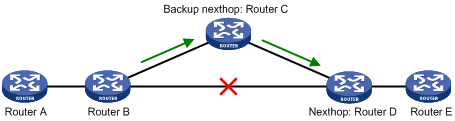
As shown in Figure 1, configure FRR on Router B by using a routing policy to specify a backup next hop. When the primary link fails, RIP directs packets to the backup next hop. At the same time, RIP calculates the shortest path based on the new network topology, and forwards packets over that path after network convergence.
Restrictions and guidelines for RIP FRR
RIP FRR takes effect only for RIP routes learned from directly connected neighbors.
RIP FRR is available only when the state of primary link (with Layer 3 interfaces staying up) changes from bidirectional to unidirectional or down.
Equal-cost routes do not support RIP FRR.
Enabling RIP FRR
1. Enter system view.
system-view
2. Configure a routing policy for FRR.
You must specify a next hop by using the apply fast-reroute backup-interface command in the routing policy.
For more information about routing policy configuration, see "Configuring routing policies."
3. Enter RIP view.
rip [ process-id ]
4. Enable RIP FRR.
fast-reroute route-policy route-policy-name
By default, RIP FRR is disabled.
Enabling BFD for RIP FRR
About BFD single-hop echo detection
By default, RIP FRR does not use BFD to detect primary link failures. For quicker RIP FRR, use BFD single-hop echo detection on the primary link of redundant links to detect link failure.
Procedure
1. Enter system view.
system-view
2. Configure the source IP address of BFD echo packets.
bfd echo-source-ip ip-address
By default, the source IP address of BFD echo packets is not configured.
The source IP address cannot be on the same network segment as any local interfaces.
For more information about this command, see High Availability Command Reference.
3. Enter interface view.
interface interface-type interface-number
4. Enable BFD for RIP FRR.
rip primary-path-detect bfd echo
By default, BFD for RIP FRR is disabled.
Enhancing RIP security
Enabling zero field check for incoming RIPv1 messages
About zero field check for incoming RIPv1 messages
Some fields in the RIPv1 message must be set to zero. These fields are called "zero fields." You can enable zero field check for incoming RIPv1 messages. If a zero field of a message contains a non-zero value, RIP does not process the message. If you are certain that all messages are trustworthy, disable zero field check to save CPU resources.
This feature does not apply to RIPv2 packets, because they have no zero fields.
Procedure
1. Enter system view.
system-view
2. Enter RIP view.
rip [ process-id ]
3. Enable zero field check for incoming RIPv1 messages.
checkzero
By default, zero field check is disabled for incoming RIPv1 messages.
Enabling source IP address check for incoming RIP updates
About source IP address check for incoming RIP updates
Perform this task to enable source IP address check for incoming RIP updates.
· Upon receiving a message on an Ethernet interface, RIP compares the source IP address of the message with the IP address of the interface. If they are not in the same network segment, RIP discards the message.
· Upon receiving a message on a PPP interface, RIP checks whether the source address of the message is the IP address of the peer interface. If not, RIP discards the message.
Procedure
1. Enter system view.
system-view
2. Enter RIP view.
rip [ process-id ]
3. Enable source IP address check for incoming RIP messages.
validate-source-address
By default, source IP address check is disabled for incoming RIP updates.
Configuring RIPv2 message authentication
About RIPv2 message authentication
Perform this task to enable authentication on RIPv2 messages.
RIPv2 supports simple authentication and MD5 authentication.
Procedure
1. Enter system view.
system-view
2. Enter interface view.
interface interface-type interface-number
3. Configure RIPv2 authentication.
rip authentication-mode { md5 { rfc2082 { cipher | plain } string key-id | rfc2453 { cipher | plain } string } | simple { cipher | plain } string }
By default, RIPv2 authentication is not configured.
RIPv1 does not support authentication. Although you can specify an authentication mode for RIPv1 in interface view, the configuration does not take effect.
Display and maintenance commands for RIP
Execute display commands in any view and execute reset commands in user view.
|
Command |
|
|
Display RIP current status and configuration information. |
display rip [ process-id ] |
|
Display RIP GR information. |
display rip [ process-id ] graceful-restart |
|
Display RIP NSR information. |
display rip [ process-id ] non-stop-routing |
|
Display active routes in the RIP database. |
display rip process-id database [ ip-address { mask-length | mask } ] |
|
Display RIP interface information. |
display rip process-id interface [ interface-type interface-number ] |
|
Display neighbor information for a RIP process. |
display rip process-id neighbor [ interface-type interface-number ] |
|
Display routing information for a RIP process. |
display rip process-id route [ ip-address { mask-length | mask } [ verbose ] | peer ip-address | statistics ] |
|
Reset a RIP process. |
reset rip process-id process |
|
Clear the statistics for a RIP process. |
reset rip process-id statistics |
RIP configuration examples
Example: Configuring basic RIP
Network configuration
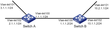
As shown in Figure 2, enable RIPv2 on all interfaces on Switch A and Switch B. Configure Switch B to not advertise route 10.2.1.0/24 to Switch A, and to accept only route 2.1.1.0/24 from Switch A.
Procedure
1. Configure IP addresses for the interfaces. (Details not shown.)
2. Enable RIP.
# Enable RIP on the specified networks on Switch A.
<SwitchA> system-view
[SwitchA] rip
[SwitchA-rip-1] network 1.0.0.0
[SwitchA-rip-1] network 2.0.0.0
[SwitchA-rip-1] network 3.0.0.0
[SwitchA-rip-1] quit
# Enable RIP on the specified interfaces on Switch B.
<SwitchB> system-view
[SwitchB] rip
[SwitchB-rip-1] quit
[SwitchB] interface vlan-interface 100
[SwitchB-Vlan-interface100] rip 1 enable
[SwitchB-Vlan-interface100] quit
[SwitchB] interface vlan-interface 101
[SwitchB-Vlan-interface101] rip 1 enable
[SwitchB-Vlan-interface101] quit
[SwitchB] interface vlan-interface 102
[SwitchB-Vlan-interface102] rip 1 enable
[SwitchB-Vlan-interface102] quit
# Display the RIP routing table of Switch A.
[SwitchA] display rip 1 route
Route Flags: R - RIP, T - TRIP
P - Permanent, A - Aging, S - Suppressed, G - Garbage-collect
D - Direct, O - Optimal, F - Flush to RIB
----------------------------------------------------------------------------
Peer 1.1.1.2 on Vlan-interface100
Destination/Mask Nexthop Cost Tag Flags Sec
10.0.0.0/8 1.1.1.2 1 0 RAOF 11
Local route
Destination/Mask Nexthop Cost Tag Flags Sec
1.1.1.0/24 0.0.0.0 0 0 RDOF -
2.1.1.0/24 0.0.0.0 0 0 RDOF -
3.1.1.0/24 0.0.0.0 0 0 RDOF -
The output shows that RIPv1 uses a natural mask.
3. Configure a RIP version:
# Configure RIPv2 on Switch A.
[SwitchA] rip
[SwitchA-rip-1] version 2
[SwitchA-rip-1] undo summary
[SwitchA-rip-1] quit
# Configure RIPv2 on Switch B.
[SwitchB] rip
[SwitchB-rip-1] version 2
[SwitchB-rip-1] undo summary
[SwitchB-rip-1] quit
# Display the RIP routing table on Switch A.
[SwitchA] display rip 1 route
Route Flags: R - RIP, T - TRIP
P - Permanent, A - Aging, S - Suppressed, G - Garbage-collect
D - Direct, O - Optimal, F - Flush to RIB
----------------------------------------------------------------------------
Peer 1.1.1.2 on Vlan-interface100
Destination/Mask Nexthop Cost Tag Flags Sec
10.0.0.0/8 1.1.1.2 1 0 RAOF 50
10.2.1.0/24 1.1.1.2 1 0 RAOF 16
10.1.1.0/24 1.1.1.2 1 0 RAOF 16
Local route
Destination/Mask Nexthop Cost Tag Flags Sec
1.1.1.0/24 0.0.0.0 0 0 RDOF -
2.1.1.0/24 0.0.0.0 0 0 RDOF -
3.1.1.0/24 0.0.0.0 0 0 RDOF -
The output shows that RIPv2 uses classless subnet masks.
|
|
NOTE: After RIPv2 is configured, RIPv1 routes might still exist in the routing table until they are aged out. |
# Display the RIP routing table on Switch B.
[SwitchB] display rip 1 route
Route Flags: R - RIP, T - TRIP
P - Permanent, A - Aging, S - Suppressed, G - Garbage-collect
D - Direct, O - Optimal, F - Flush to RIB
----------------------------------------------------------------------------
Peer 1.1.1.1 on Vlan-interface100
Destination/Mask Nexthop Cost Tag Flags Sec
2.1.1.0/24 1.1.1.1 1 0 RAOF 19
3.1.1.0/24 1.1.1.1 1 0 RAOF 19
Local route
Destination/Mask Nexthop Cost Tag Flags Sec
1.1.1.0/24 0.0.0.0 0 0 RDOF -
10.1.1.0/24 0.0.0.0 0 0 RDOF -
10.2.1.0/24 0.0.0.0 0 0 RDOF -
4. Configure route filtering:
# Reference IP prefix lists on Switch B to filter received and redistributed routes.
[SwitchB] ip prefix-list aaa index 10 permit 2.1.1.0 24
[SwitchB] ip prefix-list bbb index 10 deny 10.2.1.0 24
[SwitchB] ip prefix-list bbb index 11 permit 0.0.0.0 0 less-equal 32
[SwitchB] rip 1
[SwitchB-rip-1] filter-policy prefix-list aaa import
[SwitchB-rip-1] filter-policy prefix-list bbb export
[SwitchB-rip-1] quit
# Display the RIP routing table on Switch A.
[SwitchA] display rip 100 route
Route Flags: R - RIP, T - TRIP
P - Permanent, A - Aging, S - Suppressed, G - Garbage-collect
----------------------------------------------------------------------------
Peer 1.1.1.2 on Vlan-interface100
Destination/Mask Nexthop Cost Tag Flags Sec
10.1.1.0/24 1.1.1.2 1 0 RAOF 19
Local route
Destination/Mask Nexthop Cost Tag Flags Sec
1.1.1.0/24 0.0.0.0 0 0 RDOF -
2.1.1.0/24 0.0.0.0 0 0 RDOF -
3.1.1.0/24 0.0.0.0 0 0 RDOF -
# Display the RIP routing table on Switch B.
[SwitchB] display rip 1 route
Route Flags: R - RIP, T - TRIP
P - Permanent, A - Aging, S - Suppressed, G - Garbage-collect
D - Direct, O - Optimal, F - Flush to RIB
----------------------------------------------------------------------------
Peer 1.1.1.1 on Vlan-interface100
Destination/Mask Nexthop Cost Tag Flags Sec
2.1.1.0/24 1.1.1.1 1 0 RAOF 19
Local route
Destination/Mask Nexthop Cost Tag Flags Sec
1.1.1.0/24 0.0.0.0 0 0 RDOF -
10.1.1.0/24 0.0.0.0 0 0 RDOF -
10.2.1.0/24 0.0.0.0 0 0 RDOF -
Example: Configuring RIP route redistribution
Network configuration
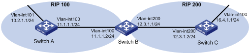
As shown in Figure 3, Switch B communicates with Switch A through RIP 100 and with Switch C through RIP 200.
Configure RIP 200 to redistribute direct routes and routes from RIP 100 on Switch B so Switch C can learn routes destined for 10.2.1.0/24 and 11.1.1.0/24. Switch A cannot learn routes destined for 12.3.1.0/24 and 16.4.1.0/24.
Procedure
1. Configure IP addresses for the interfaces. (Details not shown.)
2. Configure basic RIP settings:
# Enable RIP 100, and configure RIPv2 on Switch A.
<SwitchA> system-view
[SwitchA] rip 100
[SwitchA-rip-100] network 10.0.0.0
[SwitchA-rip-100] network 11.0.0.0
[SwitchA-rip-100] version 2
[SwitchA-rip-100] undo summary
[SwitchA-rip-100] quit
# Enable RIP 100 and RIP 200, and configure RIPv2 on Switch B.
<SwitchB> system-view
[SwitchB] rip 100
[SwitchB-rip-100] network 11.0.0.0
[SwitchB-rip-100] version 2
[SwitchB-rip-100] undo summary
[SwitchB-rip-100] quit
[SwitchB] rip 200
[SwitchB-rip-200] network 12.0.0.0
[SwitchB-rip-200] version 2
[SwitchB-rip-200] undo summary
[SwitchB-rip-200] quit
# Enable RIP 200, and configure RIPv2 on Switch C.
<SwitchC> system-view
[SwitchC] rip 200
[SwitchC-rip-200] network 12.0.0.0
[SwitchC-rip-200] network 16.0.0.0
[SwitchC-rip-200] version 2
[SwitchC-rip-200] undo summary
[SwitchC-rip-200] quit
# Display the IP routing table on Switch C.
[SwitchC] display ip routing-table
Destinations : 13 Routes : 13
Destination/Mask Proto Pre Cost NextHop Interface
0.0.0.0/32 Direct 0 0 127.0.0.1 InLoop0
12.3.1.0/24 Direct 0 0 12.3.1.2 Vlan200
12.3.1.0/32 Direct 0 0 12.3.1.2 Vlan200
12.3.1.2/32 Direct 0 0 127.0.0.1 InLoop0
12.3.1.255/32 Direct 0 0 12.3.1.2 Vlan200
16.4.1.0/24 Direct 0 0 16.4.1.1 Vlan400
16.4.1.0/32 Direct 0 0 16.4.1.1 Vlan400
16.4.1.1/32 Direct 0 0 127.0.0.1 InLoop0
16.4.1.255/32 Direct 0 0 16.4.1.1 Vlan400
127.0.0.0/8 Direct 0 0 127.0.0.1 InLoop0
127.0.0.0/32 Direct 0 0 127.0.0.1 InLoop0
127.0.0.1/32 Direct 0 0 127.0.0.1 InLoop0
127.255.255.255/32 Direct 0 0 127.0.0.1 InLoop0
3. Configure route redistribution:
# Configure RIP 200 to redistribute routes from RIP 100 and direct routes on Switch B.
[SwitchB] rip 200
[SwitchB-rip-200] import-route rip 100
[SwitchB-rip-200] import-route direct
[SwitchB-rip-200] quit
# Display the IP routing table on Switch C.
[SwitchC] display ip routing-table
Destinations : 15 Routes : 15
Destination/Mask Proto Pre Cost NextHop Interface
0.0.0.0/32 Direct 0 0 127.0.0.1 InLoop0
10.2.1.0/24 RIP 100 1 12.3.1.1 Vlan200
11.1.1.0/24 RIP 100 1 12.3.1.1 Vlan200
12.3.1.0/24 Direct 0 0 12.3.1.2 Vlan200
12.3.1.0/32 Direct 0 0 12.3.1.2 Vlan200
12.3.1.2/32 Direct 0 0 127.0.0.1 InLoop0
12.3.1.255/32 Direct 0 0 12.3.1.2 Vlan200
16.4.1.0/24 Direct 0 0 16.4.1.1 Vlan400
16.4.1.0/32 Direct 0 0 16.4.1.1 Vlan400
16.4.1.1/32 Direct 0 0 127.0.0.1 InLoop0
16.4.1.255/32 Direct 0 0 16.4.1.1 Vlan400
127.0.0.0/8 Direct 0 0 127.0.0.1 InLoop0
127.0.0.0/32 Direct 0 0 127.0.0.1 InLoop0
127.0.0.1/32 Direct 0 0 127.0.0.1 InLoop0
127.255.255.255/32 Direct 0 0 127.0.0.1 InLoop0
Example: Configuring an additional metric for a RIP interface
Network configuration
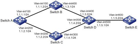
As shown in Figure 4, run RIPv2 on all the interfaces of Switch A, Switch B, Switch C, Switch D, and Switch E.
Switch A has two links to Switch D. The link from Switch B to Switch D is more stable than that from Switch C to Switch D. Configure an additional metric for RIP routes received from VLAN-interface 200 on Switch A so Switch A prefers route 1.1.5.0/24 learned from Switch B.
Procedure
1. Configure IP addresses for the interfaces. (Details not shown.)
2. Configure basic RIP settings:
# Configure Switch A.
<SwitchA> system-view
[SwitchA] rip 1
[SwitchA-rip-1] network 1.0.0.0
[SwitchA-rip-1] version 2
[SwitchA-rip-1] undo summary
[SwitchA-rip-1] quit
# Configure Switch B.
<SwitchB> system-view
[SwitchB] rip 1
[SwitchB-rip-1] network 1.0.0.0
[SwitchB-rip-1] version 2
[SwitchB-rip-1] undo summary
# Configure Switch C.
<SwitchC> system-view
[SwitchB] rip 1
[SwitchC-rip-1] network 1.0.0.0
[SwitchC-rip-1] version 2
[SwitchC-rip-1] undo summary
# Configure Switch D.
<SwitchD> system-view
[SwitchD] rip 1
[SwitchD-rip-1] network 1.0.0.0
[SwitchD-rip-1] version 2
[SwitchD-rip-1] undo summary
# Configure Switch E.
<SwitchE> system-view
[SwitchE] rip 1
[SwitchE-rip-1] network 1.0.0.0
[SwitchE-rip-1] version 2
[SwitchE-rip-1] undo summary
# Display all active routes in the RIP database on Switch A.
[SwitchA] display rip 1 database
1.0.0.0/8, auto-summary
1.1.1.0/24, cost 0, nexthop 1.1.1.1, RIP-interface
1.1.2.0/24, cost 0, nexthop 1.1.2.1, RIP-interface
1.1.3.0/24, cost 1, nexthop 1.1.1.2
1.1.4.0/24, cost 1, nexthop 1.1.2.2
1.1.5.0/24, cost 2, nexthop 1.1.1.2
1.1.5.0/24, cost 2, nexthop 1.1.2.2
The output shows two RIP routes destined for network 1.1.5.0/24, with the next hops as Switch B (1.1.1.2) and Switch C (1.1.2.2), and with the same cost of 2.
3. Configure an additional metric for a RIP interface:
# Configure an inbound additional metric of 3 for RIP-enabled interface VLAN-interface 200 on Switch A.
[SwitchA] interface vlan-interface 200
[SwitchA-Vlan-interface200] rip metricin 3
# Display all active routes in the RIP database on Switch A.
[SwitchA-Vlan-interface200] display rip 1 database
1.0.0.0/8, auto-summary
1.1.1.0/24, cost 0, nexthop 1.1.1.1, RIP-interface
1.1.2.0/24, cost 0, nexthop 1.1.2.1, RIP-interface
1.1.3.0/24, cost 1, nexthop 1.1.1.2
1.1.4.0/24, cost 2, nexthop 1.1.1.2
1.1.5.0/24, cost 2, nexthop 1.1.1.2
The output shows that only one RIP route reaches network 1.1.5.0/24, with the next hop as Switch B (1.1.1.2) and a cost of 2.
Example: Configuring RIP to advertise a summary route
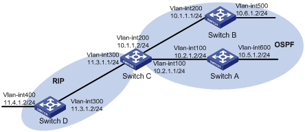
Network configuration
As shown in Figure 5, Switch A and Switch B run OSPF, Switch D runs RIP, and Switch C runs OSPF and RIP. Configure RIP to redistribute OSPF routes on Switch C so Switch D can learn routes destined for networks 10.1.1.0/24, 10.2.1.0/24, 10.5.1.0/24, and 10.6.1.0/24.
To reduce the routing table size of Switch D, configure route summarization on Switch C to advertise only the summary route 10.0.0.0/8 to Switch D.
Procedure
1. Configure IP addresses for the interfaces. (Details not shown.)
2. Configure basic OSPF settings:
# Configure Switch A.
<SwitchA> system-view
[SwitchA] ospf
[SwitchA-ospf-1] area 0
[SwitchA-ospf-1-area-0.0.0.0] network 10.5.1.0 0.0.0.255
[SwitchA-ospf-1-area-0.0.0.0] network 10.2.1.0 0.0.0.255
[SwitchA-ospf-1-area-0.0.0.0] quit
# Configure Switch B.
<SwitchB> system-view
[SwitchB] ospf
[SwitchB-ospf-1] area 0
[SwitchB-ospf-1-area-0.0.0.0] network 10.1.1.0 0.0.0.255
[SwitchB-ospf-1-area-0.0.0.0] network 10.6.1.0 0.0.0.255
[SwitchB-ospf-1-area-0.0.0.0] quit
# Configure Switch C.
<SwitchC> system-view
[SwitchC] ospf
[SwitchC-ospf-1] area 0
[SwitchC-ospf-1-area-0.0.0.0] network 10.1.1.0 0.0.0.255
[SwitchC-ospf-1-area-0.0.0.0] network 10.2.1.0 0.0.0.255
[SwitchC-ospf-1-area-0.0.0.0] quit
[SwitchC-ospf-1] quit
3. Configure basic RIP settings:
# Configure Switch C.
[SwitchC] rip 1
[SwitchC-rip-1] network 11.3.1.0
[SwitchC-rip-1] version 2
[SwitchC-rip-1] undo summary
# Configure Switch D.
<SwitchD> system-view
[SwitchD] rip 1
[SwitchD-rip-1] network 11.0.0.0
[SwitchD-rip-1] version 2
[SwitchD-rip-1] undo summary
[SwitchD-rip-1] quit
# Configure RIP to redistribute routes from OSPF process 1 and direct routes on Switch C.
[SwitchC-rip-1] import-route direct
[SwitchC-rip-1] import-route ospf 1
[SwitchC-rip-1] quit
# Display the IP routing table on Switch D.
[SwitchD] display ip routing-table
Destinations : 15 Routes : 15
Destination/Mask Proto Pre Cost NextHop Interface
0.0.0.0/32 Direct 0 0 127.0.0.1 InLoop0
10.1.1.0/24 RIP 100 1 11.3.1.1 Vlan300
10.2.1.0/24 RIP 100 1 11.3.1.1 Vlan300
10.5.1.0/24 RIP 100 1 11.3.1.1 Vlan300
10.6.1.0/24 RIP 100 1 11.3.1.1 Vlan300
11.3.1.0/24 Direct 0 0 11.3.1.2 Vlan300
11.3.1.0/32 Direct 0 0 11.3.1.2 Vlan300
11.3.1.2/32 Direct 0 0 127.0.0.1 InLoop0
11.4.1.0/24 Direct 0 0 11.4.1.2 Vlan400
11.4.1.0/32 Direct 0 0 11.4.1.2 Vlan400
11.4.1.2/32 Direct 0 0 127.0.0.1 InLoop0
127.0.0.0/8 Direct 0 0 127.0.0.1 InLoop0
127.0.0.0/32 Direct 0 0 127.0.0.1 InLoop0
127.0.0.1/32 Direct 0 0 127.0.0.1 InLoop0
127.255.255.255/32 Direct 0 0 127.0.0.1 InLoop0
4. Configure route summarization:
# Configure route summarization on Switch C and advertise only the summary route 10.0.0.0/8.
[SwitchC] interface vlan-interface 300
[SwitchC-Vlan-interface300] rip summary-address 10.0.0.0 8
# Display the IP routing table on Switch D.
[SwitchD] display ip routing-table
Destinations : 12 Routes : 12
Destination/Mask Proto Pre Cost NextHop Interface
0.0.0.0/32 Direct 0 0 127.0.0.1 InLoop0
10.0.0.0/8 RIP 100 1 11.3.1.1 Vlan300
11.3.1.0/24 Direct 0 0 11.3.1.2 Vlan300
11.3.1.0/32 Direct 0 0 11.3.1.2 Vlan300
11.3.1.2/32 Direct 0 0 127.0.0.1 InLoop0
11.4.1.0/24 Direct 0 0 11.4.1.2 Vlan400
11.4.1.0/32 Direct 0 0 11.4.1.2 Vlan400
11.4.1.2/32 Direct 0 0 127.0.0.1 InLoop0
127.0.0.0/8 Direct 0 0 127.0.0.1 InLoop0
127.0.0.0/32 Direct 0 0 127.0.0.1 InLoop0
127.0.0.1/32 Direct 0 0 127.0.0.1 InLoop0
127.255.255.255/32 Direct 0 0 127.0.0.1 InLoop0
Example: Configuring RIP GR
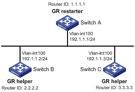
Network configuration
As shown in Figure 6, Switch A, Switch B, and Switch C all run RIPv2.
· Enable GR on Switch A. Switch A acts as the GR restarter.
· Switch B and Switch C act as GR helpers to synchronize their routing tables with Switch A by using GR.
Procedure
1. Configure IP addresses and subnet masks for the interfaces on the switches. (Details not shown.)
2. Configure RIPv2 on the switches to ensure the following: (Details not shown.)
¡ Switch A, Switch B, and Switch C can communicate with each other at Layer 3.
¡ Dynamic route update can be implemented among them with RIPv2.
3. Enable RIP GR on Switch A.
<SwitchA> system-view
[SwitchA] rip
[SwitchA-rip-1] graceful-restart
Verifying the configuration
# Restart RIP or trigger an active/standby switchover, and then display GR status on Switch A.
<SwitchA> display rip graceful-restart
RIP process: 1
Graceful Restart capability : Enabled
Current GR state : Normal
Graceful Restart period : 60 seconds
Graceful Restart remaining time : 0 seconds
Example: Configuring RIP NSR
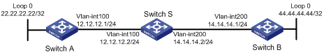
Network configuration
As shown in Figure 7, Switch A, Switch B, and Switch S all run RIPv2.
Enable RIP NSR on Switch S to ensure correct routing when an active/standby switchover occurs on Switch S.
Procedure
1. Configure IP addresses and subnet masks for the interfaces on the switches. (Details not shown.)
2. Configure RIPv2 on the switches to ensure the following: (Details not shown.)
¡ Switch A, Switch B, and Switch S can communicate with each other at Layer 3.
¡ Dynamic route update can be implemented among them with RIPv2.
3. Enable RIP NSR on Switch S.
<SwitchS> system-view
[SwitchS] rip 100
[SwitchS-rip-100] non-stop-routing
[SwitchS-rip-100] quit
Verifying the configuration
# Perform an active/standby switchover on Switch S.
[SwitchS] placement reoptimize
Predicted changes to the placement
Program Current location New location
---------------------------------------------------------------------
lb 0/0 0/0
lsm 0/0 0/0
slsp 0/0 0/0
rib6 0/0 0/0
routepolicy 0/0 0/0
rib 0/0 0/0
staticroute6 0/0 0/0
staticroute 0/0 0/0
ospf 0/0 1/0
Continue? [y/n]:y
Re-optimization of the placement start. You will be notified on completion
Re-optimization of the placement complete. Use 'display placement' to view the new placement
# Display neighbor information and route information on Switch A.
[SwitchA] display rip 1 neighbor
Neighbor Address: 12.12.12.2
Interface : Vlan-interface200
Version : RIPv2 Last update: 00h00m13s
Relay nbr : No BFD session: None
Bad packets: 0 Bad routes : 0
[SwitchA] display rip 1 route
Route Flags: R - RIP, T - TRIP
P - Permanent, A - Aging, S - Suppressed, G - Garbage-collect
D - Direct, O - Optimal, F - Flush to RIB
----------------------------------------------------------------------------
Peer 12.12.12.2 on Vlan-interface200
Destination/Mask Nexthop Cost Tag Flags Sec
14.0.0.0/8 12.12.12.2 1 0 RAOF 16
44.0.0.0/8 12.12.12.2 2 0 RAOF 16
Local route
Destination/Mask Nexthop Cost Tag Flags Sec
12.12.12.0/24 0.0.0.0 0 0 RDOF -
22.22.22.22/32 0.0.0.0 0 0 RDOF -
# Display neighbor information and route information on Switch B.
[SwitchB] display rip 1 neighbor
Neighbor Address: 14.14.14.2
Interface : Vlan-interface200
Version : RIPv2 Last update: 00h00m32s
Relay nbr : No BFD session: None
Bad packets: 0 Bad routes : 0
[SwitchB] display rip 1 route
Route Flags: R - RIP, T - TRIP
P - Permanent, A - Aging, S - Suppressed, G - Garbage-collect
D - Direct, O - Optimal, F - Flush to RIB
----------------------------------------------------------------------------
Peer 14.14.14.2 on Vlan-interface200
Destination/Mask Nexthop Cost Tag Flags Sec
12.0.0.0/8 14.14.14.2 1 0 RAOF 1
22.0.0.0/8 14.14.14.2 2 0 RAOF 1
Local route
Destination/Mask Nexthop Cost Tag Flags Sec
44.44.44.44/32 0.0.0.0 0 0 RDOF -
14.14.14.0/24 0.0.0.0 0 0 RDOF -
The output shows that the neighbor and route information on Switch A and Switch B keep unchanged during the active/standby switchover on Switch S. The traffic from Switch A to Switch B has not been impacted.
Example: Configuring BFD for RIP (single-hop echo detection for a directly connected neighbor)
Network configuration
As shown in Figure 8, VLAN-interface 100 of Switch A and Switch C runs RIP process 1. VLAN-interface 200 of Switch A runs RIP process 2. VLAN-interface 300 of Switch C and VLAN-interface 200 and VLAN-interface 300 of Switch B run RIP process 1.
· Configure a static route destined for 100.1.1.1/24 and enable static route redistribution into RIP on Switch C. This allows Switch A to learn two routes destined for 100.1.1.1/24 through VLAN-interface 100 and VLAN-interface 200 respectively, and uses the one through VLAN-interface 100.
· Enable BFD for RIP on VLAN-interface 100 of Switch A. When the link over VLAN-interface 100 fails, BFD can quickly detect the failure and notify RIP. RIP deletes the neighbor relationship and route information learned on VLAN-interface 100, and uses the route destined for 100.1.1.1 24 through VLAN-interface 200.
Procedure
1. Configure IP addresses for the interfaces. (Details not shown.)
2. Configure basic RIP settings:
# Configure Switch A.
<SwitchA> system-view
[SwitchA] rip 1
[SwitchA-rip-1] version 2
[SwitchA-rip-1] undo summary
[SwitchA-rip-1] network 192.168.1.0
[SwitchA-rip-1] quit
[SwitchA] interface vlan-interface 100
[SwitchA-Vlan-interface100] rip bfd enable
[SwitchA-Vlan-interface100] quit
[SwitchA] rip 2
[SwitchA-rip-2] version 2
[SwitchA-rip-2] undo summary
[SwitchA-rip-2] network 192.168.2.0
[SwitchA-rip-2] quit
# Configure Switch B.
<SwitchB> system-view
[SwitchB] rip 1
[SwitchB-rip-1] version 2
[SwitchB-rip-1] undo summary
[SwitchB-rip-1] network 192.168.2.0
[SwitchB-rip-1] network 192.168.3.0
[SwitchB-rip-1] quit
# Configure Switch C.
<SwitchC> system-view
[SwitchC] rip 1
[SwitchC-rip-1] version 2
[SwitchC-rip-1] undo summary
[SwitchC-rip-1] network 192.168.1.0
[SwitchC-rip-1] network 192.168.3.0
[SwitchC-rip-1] import-route static
[SwitchC-rip-1] quit
3. Configure BFD parameters on VLAN-interface 100 of Switch A.
[SwitchA] bfd echo-source-ip 11.11.11.11
[SwitchA] interface vlan-interface 100
[SwitchA-Vlan-interface100] bfd min-echo-receive-interval 500
[SwitchA-Vlan-interface100] bfd detect-multiplier 7
[SwitchA-Vlan-interface100] quit
[SwitchA] quit
4. Configure a static route on Switch C.
[SwitchC] ip route-static 120.1.1.1 24 null 0
Verifying the configuration
# Display the BFD session information on Switch A.
<SwitchA> display bfd session
Total Session Num: 1 Up Session Num: 1 Init Mode: Active
IPv4 Session Working Under Echo Mode:
LD SourceAddr DestAddr State Holdtime Interface
4 192.168.1.1 192.168.1.2 Up 2000ms Vlan100
# Display RIP routes destined for 120.1.1.0/24 on Switch A.
<SwitchA> display ip routing-table 120.1.1.0 24
Summary count : 1
Destination/Mask Proto Pre Cost NextHop Interface
120.1.1.0/24 RIP 100 1 192.168.1.2 Vlan-interface100
The output shows that Switch A communicates with Switch C through VLAN-interface 100. Then the link over VLAN-interface 100 fails.
# Display RIP routes destined for 120.1.1.0/24 on Switch A.
<SwitchA> display ip routing-table 120.1.1.0 24
Summary count : 1
Destination/Mask Proto Pre Cost NextHop Interface
120.1.1.0/24 RIP 100 1 192.168.2.2 Vlan-interface200
The output shows that Switch A communicates with Switch C through VLAN-interface 200.
Example: Configuring BFD for RIP (single hop echo detection for a specific destination)
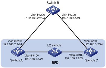
Network configuration
As shown in Figure 9, VLAN-interface 100 of Switch A and Switch B runs RIP process 1. VLAN-interface 200 of Switch B and Switch C runs RIP process 1.
· Configure a static route destined for 100.1.1.0/24 and enable static route redistribution into RIP on both Switch A and Switch C. This allows Switch B to learn two routes destined for 100.1.1.0/24 through VLAN-interface 100 and VLAN-interface 200. The route redistributed from Switch A has a smaller cost than that redistributed from Switch C, so Switch B uses the route through VLAN-interface 200.
· Enable BFD for RIP on VLAN-interface 100 of Switch A, and specify VLAN-interface 100 of Switch B as the destination. When a unidirectional link occurs between Switch A and Switch B, BFD can quickly detect the link failure and notify RIP. Switch B then deletes the neighbor relationship and the route information learned on VLAN-interface 100. It does not receive or send any packets from VLAN-interface 100. When the route learned from Switch A ages out, Switch B uses the route destined for 100.1.1.1 24 through VLAN-interface 200.
Procedure
1. Configure IP addresses for the interfaces. (Details not shown.)
2. Configure basic RIP settings and enable BFD on the interfaces:
# Configure Switch A.
<SwitchA> system-view
[SwitchA] rip 1
[SwitchA-rip-1] network 192.168.2.0
[SwitchA-rip-1] import-route static
[SwitchA-rip-1] quit
[SwitchA] interface vlan-interface 100
[SwitchA-Vlan-interface100] rip bfd enable destination 192.168.2.2
[SwitchA-Vlan-interface100] quit
# Configure Switch B.
<SwitchB> system-view
[SwitchB] rip 1
[SwitchB-rip-1] network 192.168.2.0
[SwitchB-rip-1] network 192.168.3.0
[SwitchB-rip-1] quit
# Configure Switch C.
<SwitchC> system-view
[SwitchC] rip 1
[SwitchC-rip-1] network 192.168.3.0
[SwitchC-rip-1] import-route static cost 3
[SwitchC-rip-1] quit
3. Configure BFD parameters on VLAN-interface 100 of Switch A.
[SwitchA] bfd echo-source-ip 11.11.11.11
[SwitchA] interface vlan-interface 100
[SwitchA-Vlan-interface100] bfd min-echo-receive-interval 500
[SwitchA-Vlan-interface100] return
4. Configure static routes:
# Configure a static route on Switch A.
[SwitchA] ip route-static 100.1.1.0 24 null 0
# Configure a static route on Switch C.
[SwitchA] ip route-static 100.1.1.0 24 null 0
Verifying the configuration
# Display BFD session information on Switch A.
<SwitchA> display bfd session
Total Session Num: 1 Up Session Num: 1 Init Mode: Active
IPv4 session working under Echo mode:
LD SourceAddr DestAddr State Holdtime Interface
3 192.168.2.1 192.168.2.2 Up 2000ms vlan100
# Display routes destined for 100.1.1.0/24 on Switch B.
<SwitchB> display ip routing-table 100.1.1.0 24 verbose
Summary Count : 1
Destination: 100.1.1.0/24
Protocol: RIP
Process ID: 1
SubProtID: 0x1 Age: 00h02m47s
Cost: 1 Preference: 100
IpPre: N/A QosLocalID: N/A
Tag: 0 State: Active Adv
OrigTblID: 0x0 OrigVrf: default-vrf
TableID: 0x2 OrigAs: 0
NibID: 0x12000002 LastAs: 0
AttrID: 0xffffffff Neighbor: 192.168.2.1
Flags: 0x1008c OrigNextHop: 192.168.2.1
Label: NULL RealNextHop: 192.168.2.1
BkLabel: NULL BkNextHop: N/A
Tunnel ID: Invalid Interface: vlan-interface 100
BkTunnel ID: Invalid BkInterface: N/A
FtnIndex: 0x0 TrafficIndex: N/A
Connector: N/A PathID: 0x0
# Display routes destined for 100.1.1.0/24 on Switch B when the link between Switch A and Switch B fails.
<SwitchB> display ip routing-table 100.1.1.0 24 verbose
Summary Count : 1
Destination: 100.1.1.0/24
Protocol: RIP
Process ID: 1
SubProtID: 0x1 Age: 00h21m23s
Cost: 4 Preference: 100
IpPre: N/A QosLocalID: N/A
Tag: 0 State: Active Adv
OrigTblID: 0x0 OrigVrf: default-vrf
TableID: 0x2 OrigAs: 0
NibID: 0x12000002 LastAs: 0
AttrID: 0xffffffff Neighbor: 192.168.3.2
Flags: 0x1008c OrigNextHop: 192.168.3.2
Label: NULL RealNextHop: 192.168.3.2
BkLabel: NULL BkNextHop: N/A
Tunnel ID: Invalid Interface: vlan-interface 200
BkTunnel ID: Invalid BkInterface: N/A
FtnIndex: 0x0 TrafficIndex: N/A
Connector: N/A PathID: 0x0
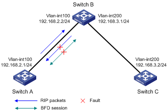
Example: Configuring BFD for RIP (bidirectional detection in BFD control packet mode)
Network configuration
As shown in Figure 10, VLAN-interface 100 of Switch A and VLAN-interface 200 of Switch C run RIP process 1.
VLAN-interface 300 of Switch A runs RIP process 2. VLAN-interface 400 of Switch C, and VLAN-interface 300 and VLAN-interface 400 of Switch D run RIP process 1.
· Configure a static route destined for 100.1.1.0/24 on Switch A.
· Configure a static route destined for 101.1.1.0/24 on Switch C.
· Enable static route redistribution into RIP on Switch A and Switch C. This allows Switch A to learn two routes destined for 100.1.1.0/24 through VLAN-interface 100 and VLAN-interface 300. It uses the route through VLAN-interface 100.
· Enable BFD on VLAN-interface 100 of Switch A and VLAN-interface 200 of Switch C.
When the link over VLAN-interface 100 fails, BFD can quickly detect the link failure and notify RIP. RIP deletes the neighbor relationship and the route information received learned on VLAN-interface 100. It uses the route destined for 100.1.1.0/24 through VLAN-interface 300.
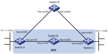
Table 1 Interface and IP address assignment
|
Device |
Interface |
IP address |
|
Switch A |
VLAN-interface 300 |
192.168.3.1/24 |
|
Switch A |
VLAN-interface 100 |
192.168.1.1/24 |
|
Switch B |
VLAN-interface 100 |
192.168.1.2/24 |
|
Switch B |
VLAN-interface 200 |
192.168.2.1/24 |
|
Switch C |
VLAN-interface 200 |
192.168.2.2/24 |
|
Switch C |
VLAN-interface 400 |
192.168.4.2/24 |
|
Switch D |
VLAN-interface 300 |
192.168.3.2/24 |
|
Switch D |
VLAN-interface 400 |
192.168.4.1/24 |
Procedure
1. Configure IP addresses for the interfaces. (Details not shown.)
2. Configure basic RIP settings and enable static route redistribution into RIP so Switch A and Switch C have routes to send to each other:
# Configure Switch A.
<SwitchA> system-view
[SwitchA] rip 1
[SwitchA-rip-1] version 2
[SwitchA-rip-1] undo summary
[SwitchA-rip-1] network 192.168.1.0
[SwitchA-rip-1] network 101.1.1.0
[SwitchA-rip-1] peer 192.168.2.2
[SwitchA-rip-1] undo validate-source-address
[SwitchA-rip-1] import-route static
[SwitchA-rip-1] quit
[SwitchA] interface vlan-interface 100
[SwitchA-Vlan-interface100] rip bfd enable
[SwitchA-Vlan-interface100] quit
[SwitchA] rip 2
[SwitchA-rip-2] version 2
[SwitchA-rip-2] undo summary
[SwitchA-rip-2] network 192.168.3.0
[SwitchA-rip-2] quit
# Configure Switch C.
<SwitchC> system-view
[SwitchC] rip 1
[SwitchC-rip-1] version 2
[SwitchC-rip-1] undo summary
[SwitchC-rip-1] network 192.168.2.0
[SwitchC-rip-1] network 192.168.4.0
[SwitchC-rip-1] network 100.1.1.0
[SwitchC-rip-1] peer 192.168.1.1
[SwitchC-rip-1] undo validate-source-address
[SwitchC-rip-1] import-route static
[SwitchC-rip-1] quit
[SwitchC] interface vlan-interface 200
[SwitchC-Vlan-interface200] rip bfd enable
[SwitchC-Vlan-interface200] quit
# Configure Switch D.
<SwitchD> system-view
[SwitchD] rip 1
[SwitchD-rip-1] version 2
[SwitchD-rip-1] undo summary
[SwitchD-rip-1] network 192.168.3.0
[SwitchD-rip-1] network 192.168.4.0
3. Configure BFD parameters:
# Configure Switch A.
[SwitchA] bfd session init-mode active
[SwitchA] interface vlan-interface 100
[SwitchA-Vlan-interface100] bfd min-transmit-interval 500
[SwitchA-Vlan-interface100] bfd min-receive-interval 500
[SwitchA-Vlan-interface100] bfd detect-multiplier 7
[SwitchA-Vlan-interface100] quit
# Configure Switch C.
[SwitchC] bfd session init-mode active
[SwitchC] interface vlan-interface 200
[SwitchC-Vlan-interface200] bfd min-transmit-interval 500
[SwitchC-Vlan-interface200] bfd min-receive-interval 500
[SwitchC-Vlan-interface200] bfd detect-multiplier 7
[SwitchC-Vlan-interface200] quit
4. Configure static routes:
# Configure a static route to Switch C on Switch A.
[SwitchA] ip route-static 192.168.2.0 24 vlan-interface 100 192.168.1.2
[SwitchA] quit
# Configure a static route to Switch A on Switch C.
[SwitchC] ip route-static 192.168.1.0 24 vlan-interface 200 192.168.2.1
Verifying the configuration
# Display the BFD session information on Switch A.
<SwitchA> display bfd session
Total Session Num: 1 Up Session Num: 1 Init Mode: Active
IPv4 session working under Ctrl mode:
LD/RD SourceAddr DestAddr State Holdtime Interface
513/513 192.168.1.1 192.168.2.2 Up 1700ms vlan100
# Display RIP routes destined for 100.1.1.0/24 on Switch A.
<SwitchA> display ip routing-table 100.1.1.0 24
Summary count : 1
Destination/Mask Proto Pre Cost NextHop Interface
100.1.1.0/24 RIP 100 1 192.168.2.2 vlan-interface 100
The output shows that Switch A communicates with Switch C through VLAN-interface 100. Then the link over VLAN-interface 100 fails.
# Display RIP routes destined for 100.1.1.0/24 on Switch A.
<SwitchA> display ip routing-table 100.1.1.0 24
Summary count : 1
Destination/Mask Proto Pre Cost NextHop Interface
100.1.1.0/24 RIP 100 2 192.168.3.2 vlan-interface 300
The output shows that Switch A communicates with Switch C through VLAN-interface 300.
Example: Configuring RIP FRR
Network configuration
As shown in Figure 11, Switch A, Switch B, and Switch C run RIPv2. Configure RIP FRR so that when Link A becomes unidirectional, services can be switched to Link B immediately.
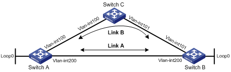
Table 2 Interface and IP address assignment
|
Device |
Interface |
IP address |
|
Switch A |
VLAN-interface 100 |
12.12.12.1/24 |
|
Switch A |
VLAN-interface 200 |
13.13.13.1/24 |
|
Switch A |
Loopback 0 |
1.1.1.1/32 |
|
Switch B |
VLAN-interface 101 |
24.24.24.4/24 |
|
Switch B |
VLAN-interface 200 |
13.13.13.2/24 |
|
Switch B |
Loopback 0 |
4.4.4.4/32 |
|
Switch C |
VLAN-interface 100 |
12.12.12.2/24 |
|
Switch C |
VLAN-interface 101 |
24.24.24.2/24 |
Procedure
1. Configure IP addresses and subnet masks for the interfaces on the switches. (Details not shown.)
2. Configure RIPv2 on the switches to make sure Switch A, Switch B, and Switch C can communicate with each other at Layer 3. (Details not shown.)
3. Configure RIP FRR:
# Configure Switch A.
<SwitchA> system-view
[SwitchA] ip prefix-list abc index 10 permit 4.4.4.4 32
[SwitchA] route-policy frr permit node 10
[SwitchA-route-policy-frr-10] if-match ip address prefix-list abc
[SwitchA-route-policy-frr-10] apply fast-reroute backup-interface vlan-interface 100 backup-nexthop 12.12.12.2
[SwitchA-route-policy-frr-10] quit
[SwitchA] rip 1
[SwitchA-rip-1] fast-reroute route-policy frr
[SwitchA-rip-1] quit
# Configure Switch B.
<SwitchB> system-view
[SwitchB] ip prefix-list abc index 10 permit 1.1.1.1 32
[SwitchB] route-policy frr permit node 10
[SwitchB-route-policy-frr-10] if-match ip address prefix-list abc
[SwitchB-route-policy-frr-10] apply fast-reroute backup-interface vlan-interface 101 backup-nexthop 24.24.24.2
[SwitchB-route-policy-frr-10] quit
[SwitchB] rip 1
[SwitchB-rip-1] fast-reroute route-policy frr
[SwitchB-rip-1] quit
Verifying the configuration
# Display route 4.4.4.4/32 on Switch A to view the backup next hop information.
[SwitchA] display ip routing-table 4.4.4.4 verbose
Summary Count : 1
Destination: 4.4.4.4/32
Protocol: RIP
Process ID: 1
SubProtID: 0x1 Age: 04h20m37s
Cost: 1 Preference: 100
IpPre: N/A QosLocalID: N/A
Tag: 0 State: Active Adv
OrigTblID: 0x0 OrigVrf: default-vrf
TableID: 0x2 OrigAs: 0
NibID: 0x26000002 LastAs: 0
AttrID: 0xffffffff Neighbor: 13.13.13.2
Flags: 0x1008c OrigNextHop: 13.13.13.2
Label: NULL RealNextHop: 13.13.13.2
BkLabel: NULL BkNextHop: 12.12.12.2
Tunnel ID: Invalid Interface: Vlan-interface200
BkTunnel ID: Invalid BkInterface: Vlan-interface100
FtnIndex: 0x0 TrafficIndex: N/A
Connector: N/A PathID: 0x0
# Display route 1.1.1.1/32 on Switch B to view the backup next hop information.
[SwitchB] display ip routing-table 1.1.1.1 verbose
Summary Count : 1
Destination: 1.1.1.1/32
Protocol: RIP
Process ID: 1
SubProtID: 0x1 Age: 04h20m37s
Cost: 1 Preference: 100
IpPre: N/A QosLocalID: N/A
Tag: 0 State: Active Adv
OrigTblID: 0x0 OrigVrf: default-vrf
TableID: 0x2 OrigAs: 0
NibID: 0x26000002 LastAs: 0
AttrID: 0xffffffff Neighbor: 13.13.13.1
Flags: 0x1008c OrigNextHop: 13.13.13.1
Label: NULL RealNextHop: 13.13.13.1
BkLabel: NULL BkNextHop: 24.24.24.2
Tunnel ID: Invalid Interface: Vlan-interface200
BkTunnel ID: Invalid BkInterface: Vlan-interface101
FtnIndex: 0x0 TrafficIndex: N/A
Connector: N/A PathID: 0x0
