- Table of Contents
-
- H3C S12500X-AF & S12500-X & S9800 Switch Series Configuration Examples-Release 27xx-6W100
- 00-Preface
- 01-CLI configuration
- 02-RBAC configuration
- 03-Login management configuration
- 04-FTP and TFTP configuration
- 05-File system management configuration
- 06-Configuration file management configuration
- 07-Software upgrade configuration
- 08-Emergency shell configuration
- 09-Automatic configuration
- 10-Device management configuration
- 11-Tcl configuration
- 12-Python configuration
- 13-License management
- Related Documents
-
| Title | Size | Download |
|---|---|---|
| 59-IRF Configuration Examples | 129.24 KB |
|
|
|
H3C S12500X-AF & S12500-X & S9800 |
|
IRF Configuration Examples |
|
|
S12500X-AF Switch Series
S12500-X Switch Series
S9800 Switch Series
Document version: 6W100-20190628
Copyright © 2019 New H3C Technologies Co., Ltd. All rights reserved.
No part of this manual may be reproduced or transmitted in any form or by any means without prior written consent of New H3C Technologies Co., Ltd.
Except for the trademarks of New H3C Technologies Co., Ltd., any trademarks that may be mentioned in this document are the property of their respective owners.
The information in this document is subject to change without notice
Contents
General restrictions and guidelines
Feature compatibility and configuration restrictions
IRF physical interface requirements
Example: Setting up an LACP MAD-enabled IRF fabric
Verifying the link backup function of multichassis aggregations
Verifying the link backup function of IRF connections
Introduction
This document provides examples for setting up IRF fabrics and configuring link aggregation and routing on the IRF fabrics.
Prerequisites
The configuration examples in this document were created and verified in a lab environment, and all the devices were started with the factory default configuration. When you are working on a live network, make sure you understand the potential impact of every command on your network.
This document assumes that you have basic knowledge of IRF.
General restrictions and guidelines
When you set up and configure an IRF fabric, follow the restrictions and guidelines in this section.
This section provides only the basic restrictions and guidelines that ensure a successful IRF deployment. For complete information, see IRF configuration guide for the switch.
Hardware requirements
An S12500X-AF switch can form an IRF fabric only with devices of the same model. In addition, an S12500X-AF switch that uses type-H service modules cannot form an IRF fabric with an S12500X-AF switch that uses type-F service modules.
An S12500-X switch can form an IRF fabric only with devices of the same model.
An S9800 switch can form an IRF fabric only with devices of the same model.
An S12500X-AF, S12500-X, or S9800 IRF fabric can contain a maximum of two member devices.
As a best practice, the following card deployment items are the same across member chassis:
· Number of cards installed on each chassis.
· Card models.
· Slot numbers for the same type of cards.
The following matrix shows the IRF member ID and hardware compatibility:
|
Hardware |
IRF member ID compatibility |
|
S12501X-AF switch with type-H service modules |
1 or 2 |
|
S12502X-AF switch with type-H service modules |
1 or 2 |
|
S12504X-AF switch with type-H service modules |
1 or 2 |
|
S12508X-AF switch with type-H service modules |
1 or 3 |
|
S12512X-AF switch with type-H service modules |
1 or 5 |
|
S12516X-AF switch with type-H service modules |
1 or 5 |
|
S12500X-AF Switch Series with type-F service modules |
1 or 2 |
|
S12500-X Switch Series |
1 or 2 |
|
S9800 Switch Series |
1 or 2 |
Software requirements
All IRF member devices must run the same system software version. Make sure the software auto-update feature is enabled on all member devices.
Feature compatibility and configuration restrictions
Make sure the feature settings in Table 1 are the same across member devices.
Table 1 IRF and feature compatibility
|
Feature |
Command |
|
Enhanced ECMP mode |
ecmp mode enhanced |
|
Link aggregation capability |
link-aggregation capability |
|
System operating mode |
system-working-mode |
IRF physical interface requirements
Use the following ports on the S12500X-AF, S12500-X or S9800 switches for IRF links:
· 10GBase-T Ethernet ports operating at 10 Gbps.
· SFP+ ports operating at 10 Gbps.
· QSFP+ ports operating at 40 or 10 Gbps.
· QSFP28 ports operating at 100, 40, or 10 Gbps.
· CFP2 ports operating at 100 Gbps.
· CXP ports operating at 100 Gbps.
The 25-GE SFP28 ports and 25-GE breakout interfaces of QSFP28 ports cannot be used as IRF physical interfaces.
Connecting IRF ports
When you connect two neighboring IRF members, connect the physical interfaces of IRF-port 1 on one member to the physical interfaces of IRF-port 2 on the other.
Licensing requirements
For a license-based feature to run correctly on an IRF fabric, make sure the licenses installed for the feature on all member devices are the same. For more information about feature licensing, see Fundamentals Configuration Guide.
Example: Setting up an LACP MAD-enabled IRF fabric
Network configuration
As shown in Figure 1:
· Set up a two-chassis IRF fabric at the core layer of the network.
· Use multichassis link aggregations to connect the IRF fabric to the access switches and the upstream egress routers.
· Use LACP MAD to detect IRF split.
· Run OSPF between the IRF fabric and the egress routers.
Figure 1 LACP MAD-enabled two-chassis IRF fabric
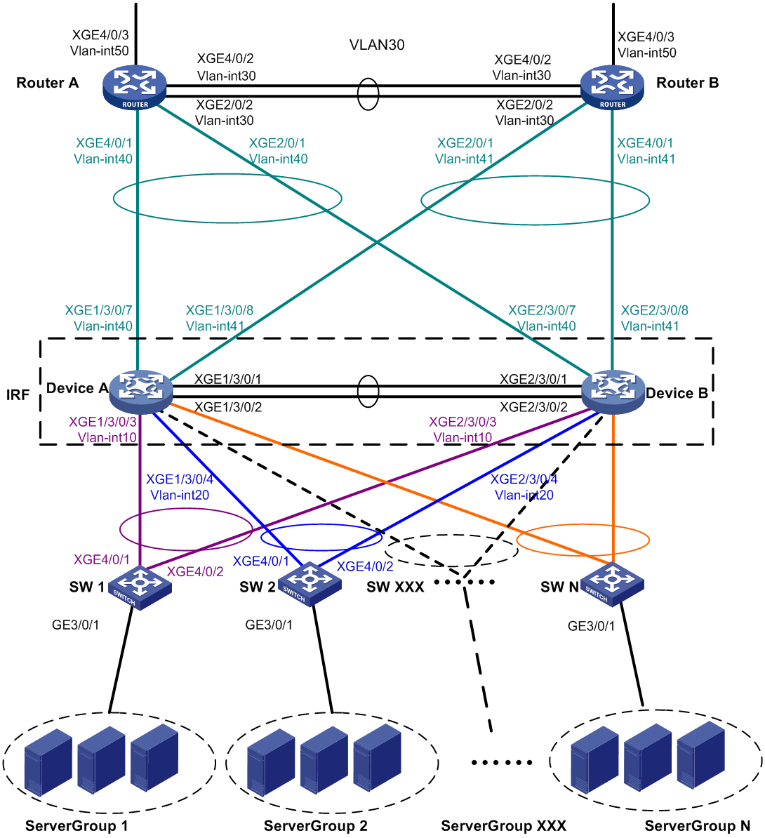
Table 2 VLAN and IP address assignment
|
Device |
VLAN interface |
IP address |
|
Router A: |
|
|
|
|
VLAN-interface 30 |
172.24.2.2/24 |
|
|
VLAN-interface 40 |
172.24.40.2/24 |
|
|
VLAN-interface 50 |
172.24.1.2/24 |
|
Router B: |
|
|
|
|
VLAN-interface 30 |
172.24.2.3/24 |
|
|
VLAN-interface 41 |
172.24.41.3/24 |
|
|
VLAN-interface 50 |
172.24.4.2/24 |
|
IRF fabric: |
|
|
|
|
VLAN-interface 10 |
172.24.10.254/24 |
|
|
VLAN-interface 20 |
172.24.20.254/24 |
|
|
VLAN-interface 40 |
172.24.40.254/24 |
|
|
VLAN-interface 41 |
172.24.41.254/24 |
Analysis
To avoid single points of failure, use multichassis link aggregations to connect the IRF fabric to the downstream and upstream devices.
For LACP MAD to run correctly, you must make sure the intermediate device supports extended LACPDUs for LACP MAD. In this example, SW 1 is used as the intermediate device for LACP MAD.
You do not need to run LACP MAD on all link aggregations. You can detect IRF split effectively by running LACP MAD on one dynamic link aggregation.
Software versions used
Table 3 shows the software versions used in this configuration example.
Table 3 Product and software version compatibility
|
Product |
Software version |
|
S12500X-AF Switch Series |
S12500X-CMW710-R2712 |
|
S12500-X Switch Series |
S12500X-CMW710-R2712 |
|
S9800 Switch Series |
S9800-CMW710-R2712 |
Restrictions and guidelines
By default, interfaces on the devices are disabled (in ADM or Administratively Down state). To have an interface operate, you must use the undo shutdown command to enable that interface.
When you configure LACP MAD on a link aggregation, follow these restrictions and guidelines:
· The link aggregation must use dynamic aggregation mode.
· The link aggregation must have a minimum of one member link from each member chassis.
· If the intermediate device is also an IRF fabric, you must assign the two IRF fabrics different domain IDs for correct split detection.
Procedures
Setting up the IRF fabric
1. Configure Device A:
# Assign member ID 1 to Device A.
<DeviceA> system-view
[DeviceA] irf member 1
# Bind Ten-GigabitEthernet 3/0/1 and Ten-GigabitEthernet 3/0/2 to IRF-port 2.
[DeviceA] irf-port 2
[DeviceA-irf-port2] port group interface ten-gigabitethernet 3/0/1
[DeviceA-irf-port2] port group interface ten-gigabitethernet 3/0/2
[DeviceA-irf-port2] quit
# Save the running configuration to the main next-startup configuration file before changing the operating mode to IRF.
|
|
IMPORTANT: The mode change requires a system reboot, which causes all unsaved settings to be lost. |
[DeviceA] save
# Enable IRF mode.
[DeviceA] chassis convert mode irf
The device will switch to IRF mode and reboot.
You are recommended to save the current running configuration and specify the configuration file for the next startup. Continue? [Y/N]:y
Do you want to convert the content of the next startup configuration file cfa0:/
irf.cfg to make it available in stack mode? [Y/N]:y
Now rebooting, please wait...
2. Configure Device B:
# Assign member ID 2 to Device B.
<DeviceB> system-view
[DeviceB] irf member 2
# Bind Ten-GigabitEthernet 3/0/1 and Ten-GigabitEthernet 3/0/2 to IRF-port 1.
[DeviceB] irf-port 1
[DeviceB-irf-port1] port group interface ten-gigabitethernet 3/0/1
[DeviceB-irf-port1] port group interface ten-gigabitethernet 3/0/2
[DeviceB-irf-port1] quit
# Save the configuration.
[DeviceB] save
# Connect the physical interfaces of IRF-port 2 on Device A to the physical interfaces of IRF-port 1 on Device B, as shown in Figure 1. (Details not shown.)
# Enable IRF mode.
[DeviceB] chassis convert mode irf
The device will switch to IRF mode and reboot.
You are recommended to save the current running configuration and specify the configuration file for the next startup. Continue? [Y/N]:y
Do you want to convert the content of the next startup configuration file cfa0:/
irf.cfg to make it available in stack mode? [Y/N]:y
Now rebooting, please wait...
Configuring software features
This example provides only basic software feature configuration.
Configuring the IRF fabric
After the IRF fabric is formed, the master's system name becomes the fabric's system name. You can configure software features on the fabric as you do on a standalone device.
1. Configure link aggregations:
# Create a Layer 2 dynamic aggregate interface named Bridge-Aggregation 1. Enable LACP MAD on the aggregate interface.
<DeviceA> system-view
[DeviceA] interface bridge-aggregation 1
[DeviceA-Bridge-Aggregation1] link-aggregation mode dynamic
[DeviceA-Bridge-Aggregation1] mad enable
You need to assign a domain ID (range: 0-4294967295)
[Current domain is: 0]:
The assigned domain ID is: 0
MAD LACP only enable on dynamic aggregation interface.
[DeviceA-Bridge-Aggregation1] quit
# Assign the downlink ports that connect to SW 1 to the aggregation group of Bridge-Aggregation 1.
[DeviceA] interface ten-gigabitethernet 1/3/0/3
[DeviceA-Ten-GigabitEthernet1/3/0/3] port link-aggregation group 1
[DeviceA-Ten-GigabitEthernet1/3/0/3] quit
[DeviceA] interface ten-gigabitethernet 2/3/0/3
[DeviceA-Ten-GigabitEthernet2/3/0/3] port link-aggregation group 1
[DeviceA-Ten-GigabitEthernet2/3/0/3] quit
# Create Bridge-Aggregation 2. Assign the downlink ports that connect to SW 2 to the aggregation group.
[DeviceA] interface bridge-aggregation 2
[DeviceA-Bridge-Aggregation2] quit
[DeviceA] interface ten-gigabitethernet 1/3/0/4
[DeviceA-Ten-GigabitEthernet1/3/0/4] port link-aggregation group 2
[DeviceA-Ten-GigabitEthernet1/3/0/4] quit
[DeviceA] interface ten-gigabitethernet 2/3/0/4
[DeviceA-Ten-GigabitEthernet2/3/0/4] port link-aggregation group 2
[DeviceA-Ten-GigabitEthernet2/3/0/4] quit
# Create Bridge-Aggregation 1023. Assign the uplink ports that connect to Router A to Bridge-Aggregation 1023.
[DeviceA] interface bridge-aggregation 1023
[DeviceA-Bridge-Aggregation1023] quit
[DeviceA] interface ten-gigabitethernet 1/3/0/7
[DeviceA-Ten-GigabitEthernet1/3/0/7] port link-aggregation group 1023
[DeviceA-Ten-GigabitEthernet1/3/0/7] quit
[DeviceA] interface ten-gigabitethernet 2/3/0/7
[DeviceA-Ten-GigabitEthernet2/3/0/7] port link-aggregation group 1023
[DeviceA-Ten-GigabitEthernet2/3/0/7] quit
# Create Bridge-Aggregation 1024. Assign the uplink ports that connect to Router B to Bridge-Aggregation 1024.
[DeviceA] interface bridge-aggregation 1024
[DeviceA-Bridge-Aggregation1024] quit
[DeviceA] interface ten-gigabitethernet 1/3/0/8
[DeviceA-Ten-GigabitEthernet1/3/0/8] port link-aggregation group 1024
[DeviceA-Ten-GigabitEthernet1/3/0/8] quit
[DeviceA] interface ten-gigabitethernet 2/3/0/8
[DeviceA-Ten-GigabitEthernet2/3/0/8] port link-aggregation group 1024
[DeviceA-Ten-GigabitEthernet2/3/0/8] quit
2. Configure VLANs, ports, and IP addresses:
# Create VLAN 10, assign an IP address to VLAN-interface 10, and assign Bridge-Aggregation 1 to VLAN 10.
[DeviceA]vlan 10
[DeviceA-vlan10] quit
[DeviceA] interface vlan-interface 10
[DeviceA-Vlan-interface10] ip address 172.24.10.254 24
[DeviceA-Vlan-interface10] quit
[DeviceA] interface bridge-aggregation 1
[DeviceA-Bridge-Aggregation1] port link-type trunk
[DeviceA-Bridge-Aggregation1] undo port trunk permit vlan 1
[DeviceA-Bridge-Aggregation1] port trunk permit vlan 10
[DeviceA-Bridge-Aggregation1] quit
# Create VLAN 20, assign an IP address to VLAN-interface 20, and assign Bridge-Aggregation 2 to VLAN 20.
[DeviceA] vlan 20
[DeviceA-vlan20] quit
[DeviceA] interface vlan-interface 20
[DeviceA-Vlan-interface20] ip address 172.24.20.254 24
[DeviceA-Vlan-interface20] quit
[DeviceA] interface bridge-aggregation 2
[DeviceA-Bridge-Aggregation2] port link-type trunk
[DeviceA-Bridge-Aggregation2] undo port trunk permit vlan 1
[DeviceA-Bridge-Aggregation2] port trunk permit vlan 20
[DeviceA-Bridge-Aggregation2] quit
# Create VLAN 40, assign an IP address to VLAN-interface 40, and assign Bridge-Aggregation 1023 to VLAN 40.
[DeviceA] vlan 40
[DeviceA-vlan40] quit
[DeviceA] interface vlan-interface 40
[DeviceA-Vlan-interface40] ip address 172.24.40.254 24
[DeviceA-Vlan-interface40] quit
[DeviceA] interface bridge-aggregation 1023
[DeviceA-Bridge-Aggregation1023] port access vlan 40
[DeviceA-Bridge-Aggregation1023] quit
# Create VLAN 41, assign an IP address to VLAN-interface 41, and assign Bridge-Aggregation 1024 to VLAN 41.
[DeviceA] vlan 41
[DeviceA-vlan41] quit
[DeviceA] interface vlan-interface 41
[DeviceA-Vlan-interface41] ip address 172.24.41.254 24
[DeviceA-Vlan-interface41] quit
[DeviceA] interface bridge-aggregation 1024
[DeviceA-Bridge-Aggregation1024] port access vlan 41
[DeviceA-Bridge-Aggregation1024] quit
3. Configure OSPF between the IRF fabric and the egress routers.
[DeviceA] ospf
[DeviceA-ospf-1] import-route direct
[DeviceA-ospf-1] area 0
[DeviceA-ospf-1-area-0.0.0.0] network 172.24.40.0 0.0.0.255
[DeviceA-ospf-1-area-0.0.0.0] network 172.24.41.0 0.0.0.255
[DeviceA-ospf-1-area-0.0.0.0] quit
[DeviceA-ospf-1] quit
Configuring SW 1
1. Configure a link aggregation:
# Create Bridge-Aggregation 1 and enable the dynamic aggregation mode. You must enable the dynamic aggregation mode because this link aggregation will be used for LACP MAD.
<SW1> system-view
[SW1] interface bridge-aggregation 1
[SW1-Bridge-Aggregation1] link-aggregation mode dynamic
[SW1-Bridge-Aggregation1] quit
# Assign the uplink ports that connect to the IRF fabric to Bridge-Aggregation 1.
[SW1] interface ten-gigabitethernet 4/0/1
[SW1-Ten-GigabitEthernet4/0/1] port link-aggregation group 1
[SW1-Ten-GigabitEthernet4/0/1] quit
[SW1] interface ten-gigabitethernet 4/0/2
[SW1-Ten-GigabitEthernet4/0/2] port link-aggregation group 1
[SW1-Ten-GigabitEthernet4/0/2] quit
2. Configure VLANs, ports, and IP addresses:
# Create all VLANs.
[SW1] vlan all
# Configure VLAN settings on the uplink aggregate interface that connects to the IRF fabric.
[SW1] interface bridge-aggregation 1
[SW1-Bridge-Aggregation1] port link-type trunk
[SW1-Bridge-Aggregation1] undo port trunk permit vlan 1
[SW1-Bridge-Aggregation1] port trunk permit vlan 10
[SW1-Bridge-Aggregation1] quit
# Configure VLAN settings on the port that connects to Server Group 1.
[SW1] interface gigabitethernet 3/0/1
[SW1-GigabitEthernet3/0/1] port link-type trunk
[SW1-GigabitEthernet3/0/1] port trunk permit vlan all
[SW1-GigabitEthernet3/0/1] undo port trunk permit vlan 1
[SW1-GigabitEthernet3/0/1] quit
Configuring SW 2
1. Configure a link aggregation:
# Create Bridge-Aggregation 1.
<SW2>system-view
[SW2] interface bridge-aggregation 1
[SW2-Bridge-Aggregation1] quit
# Assign the uplink ports that connect to the IRF fabric to Bridge-Aggregation 1.
[SW2] interface ten-gigabitethernet 4/0/1
[SW2-Ten-GigabitEthernet4/0/1] port link-aggregation group 1
[SW2-Ten-GigabitEthernet4/0/1] quit
[SW2] interface ten-gigabitethernet 4/0/2
[SW2-Ten-GigabitEthernet4/0/2] port link-aggregation group 1
[SW2-Ten-GigabitEthernet4/0/2] quit
2. Configure VLANs, ports, and IP addresses:
# Create all VLANs.
[SW2] vlan all
# Configure VLAN settings on the uplink aggregate interface that connects to the IRF fabric.
[SW2] interface bridge-aggregation 1
[SW2-Bridge-Aggregation1] port link-type trunk
[SW2-Bridge-Aggregation1] undo port trunk permit vlan 1
[SW2-Bridge-Aggregation1] port trunk permit vlan 20
[SW2-Bridge-Aggregation1] quit
# Configure VLAN settings on the port that connects to Server Group 2.
[SW2] interface gigabitethernet 3/0/1
[SW2-GigabitEthernet3/0/1] port link-type trunk
[SW2-GigabitEthernet3/0/1] port trunk permit vlan all
[SW2-GigabitEthernet3/0/1] undo port trunk permit vlan 1
[SW2-GigabitEthernet3/0/1] quit
Configuring Router A
In this example, the egress router configuration only includes the connection to the IRF fabric.
1. Configure link aggregations:
# Create Bridge-Aggregation 1. Assign the downlink ports that connect to the IRF fabric to Bridge-Aggregation 1.
<RouterA> system-view
[RouterA] interface bridge-aggregation 1
[RouterA-Bridge-Aggregation1] quit
[RouterA] interface ten-gigabitethernet 4/0/1
[RouterA-Ten-GigabitEthernet4/0/1] port link-mode bridge
[RouterA-Ten-GigabitEthernet4/0/1] port link-aggregation group 1
[RouterA-Ten-GigabitEthernet4/0/1] quit
[RouterA] interface ten-gigabitethernet 2/0/1
[RouterA-Ten-GigabitEthernet2/0/1] port link-mode bridge
[RouterA-Ten-GigabitEthernet2/0/1] port link-aggregation group 1
[RouterA-Ten-GigabitEthernet2/0/1] quit
# Create Bridge-Aggregation 2. Assign the ports that connect to Router B to Bridge-Aggregation 2.
[RouterA] interface bridge-aggregation 2
[RouterA-Bridge-Aggregation2] quit
[RouterA] interface ten-gigabitethernet 4/0/2
[RouterA-Ten-GigabitEthernet4/0/2] port link-mode bridge
[RouterA-Ten-GigabitEthernet4/0/2] port link-aggregation group 2
[RouterA-Ten-GigabitEthernet4/0/2] quit
[RouterA] interface ten-gigabitethernet 2/0/2
[RouterA-Ten-GigabitEthernet2/0/2] port link-mode bridge
[RouterA-Ten-GigabitEthernet2/0/2] port link-aggregation group 2
[RouterA-Ten-GigabitEthernet2/0/2] quit
2. Configure VLANs, ports, and IP addresses:
# Create VLAN 40, assign an IP address to VLAN-interface 40, and assign Bridge-Aggregation 1 to VLAN 40.
[RouterA] vlan 40
[RouterA-vlan40] quit
[RouterA] interface vlan-interface 40
[RouterA-vlan-interface40] ip address 172.24.40.2 24
[RouterA-vlan-interface40] quit
[RouterA] interface bridge-aggregation 1
[RouterA-Bridge-Aggregation1] port access vlan 40
[RouterA-Bridge-Aggregation1] quit
# Create VLAN 30, assign an IP address to VLAN-interface 30, and assign Bridge-Aggregation 2 to VLAN 30.
[RouterA] vlan 30
[RouterA-vlan30] quit
[RouterA] interface vlan-interface 30
[RouterA-vlan-interface30] ip address 172.24.2.2 24
[RouterA-vlan-interface30] quit
[RouterA] interface bridge-aggregation 2
[RouterA-Bridge-Aggregation2] port link-type access
[RouterA-Bridge-Aggregation2] port access vlan 30
[RouterA-Bridge-Aggregation2] quit
# Create VLAN 50, assign an IP address to VLAN-interface 50, and assign Ten-GigabitEthernet 4/0/3 to VLAN 50.
[RouterA] vlan 50
[RouterA-vlan50] quit
[RouterA] interface vlan-interface 50
[RouterA-vlan-interface50] ip address 172.24.1.2 24
[RouterA-vlan-interface50] quit
[RouterA] interface ten-gigabitethernet 4/0/3
[RouterA-Ten-GigabitEthernet4/0/3] port link-mode bridge
[RouterA-Ten-GigabitEthernet4/0/3] port access vlan 50
[RouterA-Ten-GigabitEthernet4/0/3] quit
3. Configure OSPF between Router A and the IRF fabric.
[RouterA] ospf
[RouterA-ospf-1] import-route direct
[RouterA-ospf-1] area 0
[RouterA-ospf-1-area-0.0.0.0] network 172.24.40.0 0.0.0.255
[RouterA-ospf-1-area-0.0.0.0] network 172.24.2.0 0.0.0.255
[RouterA-ospf-1-area-0.0.0.0] quit
[RouterA-ospf-1] quit
Configuring Router B
In this example, the egress router configuration only includes the connection to the IRF fabric.
1. Configure link aggregations:
# Create Bridge-Aggregation 1. Assign the downlink ports that connect to the IRF fabric to Bridge-Aggregation 1.
<RouterB> system-view
[RouterB] interface bridge-aggregation 1
[RouterB-Bridge-Aggregation1] quit
[RouterB] interface ten-gigabitethernet 4/0/1
[RouterB-Ten-GigabitEthernet4/0/1] port link-mode bridge
[RouterB-Ten-GigabitEthernet4/0/1] port link-aggregation group 1
[RouterB-Ten-GigabitEthernet4/0/1] quit
[RouterB] interface ten-gigabitethernet 2/0/1
[RouterB-Ten-GigabitEthernet2/0/1] port link-mode bridge
[RouterB-Ten-GigabitEthernet2/0/1] port link-aggregation group 1
[RouterB-Ten-GigabitEthernet2/0/1] quit
# Create Bridge-Aggregation 2. Assign the ports that connect to Router A to Bridge-Aggregation 2.
[RouterB] interface bridge-aggregation 2
[RouterB-Bridge-Aggregation2] quit
[RouterB] interface ten-gigabitethernet 4/0/2
[RouterB-Ten-GigabitEthernet4/0/2] port link-mode bridge
[RouterB-Ten-GigabitEthernet4/0/2] port link-aggregation group 2
[RouterB-Ten-GigabitEthernet4/0/2] quit
[RouterB] interface ten-gigabitethernet 2/0/2
[RouterB-Ten-GigabitEthernet2/0/2] port link-mode bridge
[RouterB-Ten-GigabitEthernet2/0/2] port link-aggregation group 2
[RouterB-Ten-GigabitEthernet2/0/2] quit
2. Configure VLANs, ports, and IP addresses:
# Create VLAN 41, assign an IP address to VLAN-interface 41, and assign Bridge-Aggregation 1 to VLAN 41.
[RouterB] vlan 41
[RouterB-vlan41] quit
[RouterB] interface vlan-interface 41
[RouterB-vlan-interface41] ip address 172.24.41.3 24
[RouterB-vlan-interface41] quit
[RouterB] interface bridge-aggregation 1
[RouterB-Bridge-Aggregation1] port access vlan 41
[RouterB-Bridge-Aggregation1] quit
# Create VLAN 30, assign an IP address to VLAN-interface 30, and assign Bridge-Aggregation 2 to VLAN 30.
[RouterB] vlan 30
[RouterB-vlan30] quit
[RouterB] interface vlan-interface 30
[RouterB-vlan-interface30] ip address 172.24.2.3 24
[RouterB-vlan-interface30] quit
[RouterB] interface bridge-aggregation 2
[RouterB-Bridge-Aggregation2] port link-type access
[RouterB-Bridge-Aggregation2] port access vlan 30
[RouterB-Bridge-Aggregation2] quit
# Create VLAN 50, assign an IP address to VLAN-interface 50, and assign Ten-GigabitEthernet 4/0/3 to VLAN 50.
[RouterB] vlan 50
[RouterB-vlan50] quit
[RouterB] interface vlan-interface 50
[RouterB-vlan-interface50] ip address 172.24.4.3 24
[RouterB-vlan-interface50] quit
[RouterB] interface ten-gigabitethernet 4/0/3
[RouterB-Ten-GigabitEthernet4/0/3] port link-mode bridge
[RouterB-Ten-GigabitEthernet4/0/3] port access vlan 50
[RouterB-Ten-GigabitEthernet4/0/3] quit
3. Configure OSPF between Router B and the IRF fabric.
[RouterB] ospf
[RouterB-ospf-1] import-route direct
[RouterB-ospf-1] area 0
[RouterB-ospf-1-area-0.0.0.0] network 172.24.41.0 0.0.0.255
[RouterB-ospf-1-area-0.0.0.0] network 172.24.2.0 0.0.0.255
[RouterB-ospf-1-area-0.0.0.0] quit
[RouterB-ospf-1] quit
Verifying the configuration
Verify the IRF setup, multichassis link aggregation configuration, and the IRF link redundancy backup function.
Verifying the IRF setup
# Verify that the IRF fabric has been formed.
[DeviceA] display irf
MemberID Slot Role Priority CPU-Mac Description
*+1 0 Master 1 0210-fc01-0000 ---
2 0 Standby 1 0210-fc02-0000 ---
--------------------------------------------------
* indicates the device is the master.
+ indicates the device through which the user logs in.
The Bridge MAC of the IRF is: 3822-d60f-2800
Auto upgrade : yes
Mac persistent : always
Domain ID : 0
Auto merge : yes
The command output shows that the member chassis have formed an IRF fabric.
Verifying the link backup function of multichassis aggregations
# Shut down Ten-GigabitEthernet 1/3/0/8, the port connected to the egress router.
[DeviceA] interface ten-gigabitethernet 1/3/0/8
[DeviceA-Ten-GigabitEthernet1/3/0/8] shutdown
# Ping an IP address on the public network from a PC in Server Group 1.
C:\Users>ping 202.108.22.5 -t
Pinging 202.108.22.5 with 32 bytes of data:
Reply from 202.108.22.5: bytes=32 time=1ms TTL=122
Reply from 202.108.22.5: bytes=32 time=13ms TTL=122
Reply from 202.108.22.5: bytes=32 time<1ms TTL=122
Request timed out.
Request timed out.
Request timed out.
Reply from 202.108.22.5: bytes=32 time<1ms TTL=122
Reply from 202.108.22.5: bytes=32 time<1ms TTL=122
Reply from 202.108.22.5: bytes=32 time<1ms TTL=122
The output shows that the address can be pinged after transient traffic disruption.
# Bring up Ten-GigabitEthernet 1/3/0/8 and shut down Ten-GigabitEthernet 2/3/0/8.
[DeviceA-Ten-GigabitEthernet1/3/0/8] undo shutdown
[DeviceA-Ten-GigabitEthernet1/3/0/8] quit
[DeviceA] interface ten-gigabitethernet 2/3/0/8
[DeviceA-Ten-GigabitEthernet2/3/0/8] shutdown
# Ping the IP address on the public network from the PC.
C:\Users>ping 202.108.22.5 -t
Pinging 202.108.22.5 with 32 bytes of data:
Reply from 202.108.22.5: bytes=32 time=1ms TTL=122
Reply from 202.108.22.5: bytes=32 time=13ms TTL=122
Reply from 202.108.22.5: bytes=32 time<1ms TTL=122
Request timed out.
Request timed out.
Request timed out.
Reply from 202.108.22.5: bytes=32 time<1ms TTL=122
Reply from 202.108.22.5: bytes=32 time<1ms TTL=122
Reply from 202.108.22.5: bytes=32 time<1ms TTL=122
The output shows that the address can be pinged after transient traffic disruption.
Verifying the link backup function of IRF connections
# Verify that the IRF fabric is integrated and can forward traffic across member chassis after one IRF connection cable is removed. (Details not shown.)
Configuration files
· IRF fabric:
#
irf mac-address persistent always
irf auto-update enable
irf auto-merge enable
undo irf link-delay
irf member 1 priority 1
irf member 2 priority 1
#
ospf 1
import-route direct
area 0.0.0.0
network 172.24.40.0 0.0.0.255
network 172.24.41.0 0.0.0.255
#
vlan 10
#
vlan 20
#
vlan 40
#
vlan 41
#
irf-port1/2
port group interface Ten-GigabitEthernet1/3/0/1 mode enhanced
port group interface Ten-GigabitEthernet1/3/0/2 mode enhanced
#
irf-port2/1
port group interface Ten-GigabitEthernet2/3/0/1 mode enhanced
port group interface Ten-GigabitEthernet2/3/0/2 mode enhanced
#
interface Bridge-Aggregation1
port link-type trunk
undo port trunk permit vlan 1
port trunk permit vlan 10
link-aggregation mode dynamic
mad enable
#
interface Bridge-Aggregation2
port link-type trunk
undo port trunk permit vlan 1
port trunk permit vlan 20
#
interface Bridge-Aggregation1023
port access vlan 40
#
interface Bridge-Aggregation1024
port access vlan 41
#
interface Vlan-interface10
ip address 172.24.10.254 255.255.255.0
#
interface Vlan-interface20
ip address 172.24.20.254 255.255.255.0
#
interface Vlan-interface40
ip address 172.24.40.254 255.255.255.0
#
interface Ten-GigabitEthernet1/3/0/3
port link-mode bridge
port link-type trunk
undo port trunk permit vlan 1
port trunk permit vlan 10
port link-aggregation group 1
#
interface Ten-GigabitEthernet1/3/0/4
port link-mode bridge
port link-type trunk
undo port trunk permit vlan 1
port trunk permit vlan 20
port link-aggregation group 2
#
interface Ten-GigabitEthernet1/3/0/7
port link-mode bridge
port access vlan 40
port link-aggregation group 1023
#
interface Ten-GigabitEthernet1/3/0/8
port link-mode bridge
port access vlan 41
port link-aggregation group 1024
#
interface Ten-GigabitEthernet2/3/0/3
port link-mode bridge
port link-type trunk
undo port trunk permit vlan 1
port trunk permit vlan 10
port link-aggregation group 1
#
interface Ten-GigabitEthernet2/3/0/4
port link-mode bridge
port link-type trunk
undo port trunk permit vlan 1
port trunk permit vlan 20
port link-aggregation group 2
#
interface Ten-GigabitEthernet2/3/0/7
port link-mode bridge
port access vlan 40
port link-aggregation group 1023
#
interface Ten-GigabitEthernet2/3/0/8
port link-mode bridge
port access vlan 41
port link-aggregation group 1024
#
· SW 1:
#
vlan 10
#
interface Bridge-Aggregation1
port link-type trunk
undo port trunk permit vlan 1
port trunk permit vlan 10
link-aggregation mode dynamic
#
interface GigabitEthernet3/0/1
port link-mode bridge
port link-type trunk
undo port trunk permit vlan 1
port trunk permit vlan 2 to 4094
#
interface Ten-GigabitEthernet4/0/1
port link-mode bridge
port link-type trunk
undo port trunk permit vlan 1
port trunk permit vlan 10
port link-aggregation group 1
#
interface Ten-GigabitEthernet4/0/2
port link-mode bridge
port link-type trunk
undo port trunk permit vlan 1
port trunk permit vlan 10
port link-aggregation group 1
#
· SW 2:
#
vlan 20
#
interface Bridge-Aggregation1
port link-type trunk
undo port trunk permit vlan 1
port trunk permit vlan 20
#
interface GigabitEthernet3/0/1
port link-mode bridge
port link-type trunk
undo port trunk permit vlan 1
port trunk permit vlan 2 to 4094
#
interface Ten-GigabitEthernet4/0/1
port link-mode bridge
port link-type trunk
undo port trunk permit vlan 1
port trunk permit vlan 20
port link-aggregation group 1
#
interface Ten-GigabitEthernet4/0/2
port link-mode bridge
port link-type trunk
undo port trunk permit vlan 1
port trunk permit vlan 20
port link-aggregation group 1
#
· Router A:
#
ospf 1
import-route direct
area 0.0.0.0
network 172.24.2.0 0.0.0.255
network 172.24.40.0 0.0.0.255
#
vlan 30
#
vlan 40
#
vlan 50
#
interface Bridge-Aggregation1
port access vlan 40
#
interface Bridge-Aggregation2
port access vlan 30
#
interface Vlan-interface30
ip address 172.24.2.2 255.255.255.0
#
interface Vlan-interface40
ip address 172.24.40.2 255.255.255.0
#
interface Vlan-interface50
ip address 172.24.1.2 255.255.255.0
#
interface Ten-GigabitEthernet2/0/1
port link-mode bridge
port access vlan 40
port link-aggregation group 1
#
interface Ten-GigabitEthernet2/0/2
port link-mode bridge
port access vlan 30
port link-aggregation group 2
#
interface Ten-GigabitEthernet4/0/1
port link-mode bridge
port access vlan 40
port link-aggregation group 1
#
interface Ten-GigabitEthernet4/0/2
port link-mode bridge
port access vlan 30
port link-aggregation group 2
#
interface Ten-GigabitEthernet4/0/3
port link-mode bridge
port access vlan 50
#
· Router B:
#
ospf 1
import-route direct
area 0.0.0.0
network 172.24.2.0 0.0.0.255
network 172.24.41.0 0.0.0.255
#
vlan 30
#
vlan 41
#
vlan 50
#
interface Bridge-Aggregation1
port access vlan 41
#
interface Bridge-Aggregation2
port access vlan 30
#
interface Vlan-interface30
ip address 172.24.2.3 255.255.255.0
#
interface Vlan-interface41
ip address 172.24.41.3 255.255.255.0
#
interface Vlan-interface50
ip address 172.24.4.3 255.255.255.0
#
interface Ten-GigabitEthernet2/0/1
port link-mode bridge
port access vlan 41
port link-aggregation group 1
#
interface Ten-GigabitEthernet2/0/2
port link-mode bridge
port access vlan 30
port link-aggregation group 2
#
interface Ten-GigabitEthernet4/0/1
port link-mode bridge
port access vlan 41
port link-aggregation group 1
#
interface Ten-GigabitEthernet4/0/2
port link-mode bridge
port access vlan 30
port link-aggregation group 2
#
interface Ten-GigabitEthernet4/0/3
port link-mode bridge
port access vlan 50
#
Related documentation
· H3C S12500X-AF & S12500-X & S9800 Switch Series Virtual Technologies Command Reference (R27xx)
· H3C S12500X-AF & S12500-X & S9800 Switch Series Virtual Technologies Configuration Guide (R27xx)
