- Table of Contents
-
- H3C S12500X-AF & S12500-X & S9800 Switch Series Configuration Examples-Release 27xx-6W100
- 00-Preface
- 01-CLI configuration
- 02-RBAC configuration
- 03-Login management configuration
- 04-FTP and TFTP configuration
- 05-File system management configuration
- 06-Configuration file management configuration
- 07-Software upgrade configuration
- 08-Emergency shell configuration
- 09-Automatic configuration
- 10-Device management configuration
- 11-Tcl configuration
- 12-Python configuration
- 13-License management
- Related Documents
-
| Title | Size | Download |
|---|---|---|
| 07-Port Isolation Configuration Examples | 51.47 KB |
|
H3C S12500X-AF & S12500-X & S9800 |
Port Isolation Configuration Examples |
|
S12500X-AF Switch Series
S12500-X Switch Series
S9800 Switch Series
Document version: 6W100-20190628
Copyright © 2019 New H3C Technologies Co., Ltd. All rights reserved.
No part of this manual may be reproduced or transmitted in any form or by any means without prior written consent of New H3C Technologies Co., Ltd.
Except for the trademarks of New H3C Technologies Co., Ltd., any trademarks that may be mentioned in this document are the property of their respective owners.
The information in this document is subject to change without notice.
Contents
General configuration restrictions and guidelines· 1
Example: Configuring port isolation· 1
Restrictions and guidelines· 2
Verifying the configuration· 2
Introduction
This document provides port isolation configuration examples.
Prerequisites
This document is not restricted to specific software or hardware versions.
The configuration examples in this document were created and verified in a lab environment, and all the devices were started with the factory default configuration. When you are working on a live network, make sure you understand the potential impact of every command on your network.
This document assumes that you have basic knowledge of port isolation.
General configuration restrictions and guidelines
You cannot assign the member ports of a service loopback group to an isolation group. You cannot assign the member ports of an isolation group to a service loopback group.
Example: Configuring port isolation
Network configuration
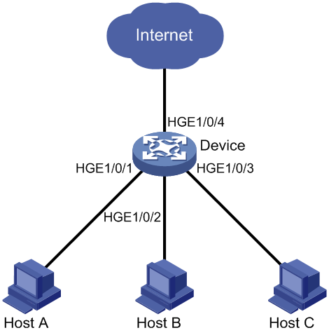
As shown in Figure 1:
· LAN users Host A, Host B, and Host C are connected to HundredGigE 1/0/1, HundredGigE 1/0/2, and HundredGigE 1/0/3 on the device, respectively.
· The device is connected to the Internet through HundredGigE 1/0/4.
Configure the device to provide Internet access for all the hosts, and isolate them from one another.
Software versions used
Table 1 shows the software versions used in this configuration example.
Table 1 Product and software version compatibility
Product | Software version |
S12500X-AF Switch Series | S12500X-CMW710-R2712 |
S12500-X Switch Series | S12500X-CMW710-R2712 |
S9800 Switch Series | S9800-CMW710-R2712 |
Restrictions and guidelines
By default, interfaces on the device are disabled (in ADM or Administratively Down state). To have an interface operate, you must use the undo shutdown command to enable that interface.
Procedures
# Assign HundredGigE 1/0/1, HundredGigE 1/0/2, HundredGigE 1/0/3 to the isolation group.
<Device> system-view
[Device] interface hundredgige 1/0/1
[Device-HundredGigE1/0/1] port-isolate enable
[Device-HundredGigE1/0/1] quit
[Device] interface hundredgige 1/0/2
[Device-HundredGigE1/0/2] port-isolate enable
[Device-HundredGigE1/0/2] quit
[Device] interface hundredgige 1/0/3
[Device-HundredGigE1/0/3] port-isolate enable
[Device-HundredGigE1/0/3] quit
Verifying the configuration
# Display information about the isolation group.
[Device] display port-isolate group
Port isolation group information:
Group ID: 1
Group members:
HundredGigE1/0/1
HundredGigE1/0/2
HundredGigE1/0/3
The output shows that HundredGigE 1/0/1, HundredGigE 1/0/2, HundredGigE 1/0/3 are in the isolation group. As a result, Host A, Host B, and Host C are isolated from one another at Layer 2.
Configuration files
#
port-isolate enable
#
interface HundredGigE1/0/1
port link-mode bridge
port-isolate enable
#
interface HundredGigE1/0/2
port link-mode bridge
port-isolate enable
#
interface HundredGigE1/0/3
port link-mode bridge
port-isolate enable
#
Related documentation
· H3C S12500X-AF & S12500-X & S9800 Switch Series Layer 2—LAN Switching Command Reference (R27xx)
· H3C S12500X-AF & S12500-X & S9800 Switch Series Layer 2—LAN Switching Configuration Guide (R27xx)
