- Table of Contents
-
- 02-WLAN Configuration Guides
- 00-Preface
- 01-AP management configuration
- 02-Radio management configuration
- 03-WLAN access configuration
- 04-WLAN security configuration
- 05-WLAN authentication configuration
- 06-WIPS configuration
- 07-WLAN QoS configuration
- 08-WLAN roaming configuration
- 09-WLAN load balancing configuration
- 10-WLAN radio resource measurement configuration
- 11-Channel scanning configuration
- 12-Band navigation configuration
- 13-WLAN high availability configuration
- 14-802.11r configuration
- 15-Wireless location configuration
- 16-AC hierarchy configuration
- 17-WLAN RRM configuration
- 18-WLAN IP snooping configuration
- 19-WLAN probe configuration
- 20-Spectrum management configuration
- 21-WLAN radio load balancing configuration
- 22-User isolation configuration
- 23-Packet capture configuration
- 24-802.1X client configuration
- 25-IP source guard configuration
- Related Documents
-
| Title | Size | Download |
|---|---|---|
| 22-User isolation configuration | 290.05 KB |
Enabling SSID-based user isolation
User isolation configuration examples
Example: Configuring SSID-based user isolation (centralized forwarding mode)
Example: Configuring SSID-based user isolation (local forwarding mode)
Configuring user isolation
About user isolation
The user isolation feature isolates packets for users that use the same SSID in the same VLAN. This feature improves user security, relieves the forwarding stress of the device, and reduces consumption of radio resources.
SSID-based user isolation
SSID-based user isolation is applicable to both the local forwarding mode and the centralized forwarding mode.
When SSID-based user isolation is enabled for a service, the device isolates all wireless users that access the network through the service in the same VLAN.
User isolation mechanism in centralized forwarding mode
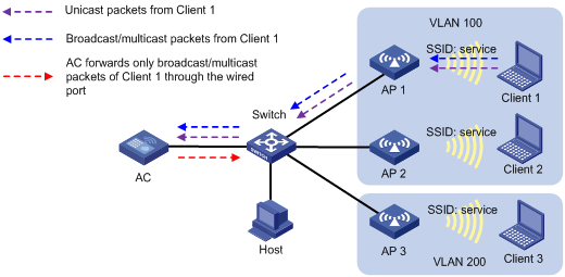
As shown in Figure 1, the AC centrally forwards the client traffic. Client 1 to Client 3 access the WLAN through AP 1 to AP 3 by using the service named service. Client 1 and Client 2 are in VLAN 100, and Client 3 is in VLAN 200. Enable user isolation on the AC for the service.
· Client 1 sends broadcast or multicast packets in VLAN 100. When the AC receives the packets, it does not forward them to any APs in the WLAN. The AC forwards the packets only through the wired port to the switch.
· Client 1 sends unicast packets to Client 2 in VLAN 100. When the AC receives the packets, it discards them instead of forwarding them to AP 2.
Figure 1 Packet forwarding path
User isolation mechanism in local forwarding mode
This mechanism isolates wireless clients on the same AP.
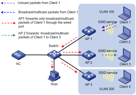
As shown in Figure 2, the APs perform local traffic forwarding for clients. Client 1 to Client 4 access the WLAN through AP 1 to AP 3 by using the service named service. Client 1 to Client 3 are in VLAN 100, and Client 4 is in VLAN 200. Enable SSID-based user isolation on the service for AP 1.
· Client 1 sends broadcast or multicast packets in VLAN 100.
¡ When AP 1 receives the packets, it does not forward them to Client 2 because user isolation is enabled. The AP forwards the packets only through the wired port to the wired devices in the same VLAN, including AP 2, AP 3, and the host.
¡ When AP 2 receives the packets, it forwards them to Client 3 because user isolation is disabled on AP 2.
¡ When AP 3 receives the packets, it does not forward them to Client 4 because Client 1 and Client 4 are in different VLANs.
· Client 1 sends unicast packets to Client 2 in VLAN 100. When AP 1 receives the packets, it discards them instead of forwarding them to Client 2.
Figure 2 Packet forwarding path
VLAN-based user isolation
VLAN-based user isolation is applicable to both local and centralized forwarding modes. Table 1 shows the mechanism to isolate traffic of wired users and wireless users.
Table 1 VLAN-based user isolation mechanism
|
Forwarding mode |
Received unicast packets |
Received broadcast or multicast packets |
|
Centralized forwarding |
The AC discards the packets. |
The AC forwards the packets only through wired ports to the wired users in the VLAN, and it does not forward the packets to wireless users in the VLAN. |
|
Local forwarding |
The fit AP discards the packets. |
The fit AP forwards the packets to wired and wireless users in the VLAN through wired ports. However, the AP does not forward the packets to the local wireless users in the VLAN. |
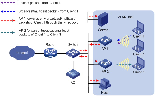
User isolation mechanism in centralized forwarding mode (packets received from wireless users)
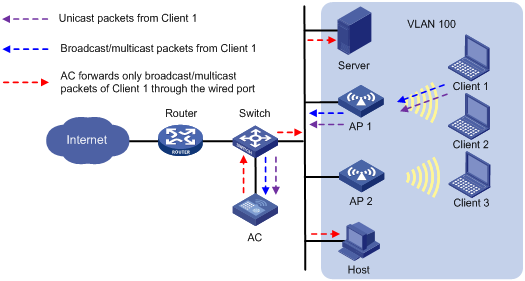
As shown in Figure 3, the AC centrally forwards the client traffic. Enable user isolation on the AC for VLAN 100.
· Client 1 sends broadcast or multicast packets in VLAN 100. When the AC receives the packets, it does not forward them to any APs in the WLAN. The AC forwards the packets only through the wired port to the switch. The switch then forwards the packets to the wired host and server.
· Client 1 sends unicast packets to Client 3 in VLAN 100. When the AC receives the packets, it discards them instead of forwarding them to AP 2.
Figure 3 Packet forwarding path
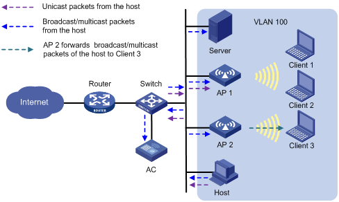
User isolation mechanism in centralized forwarding mode (packets received from wired users)
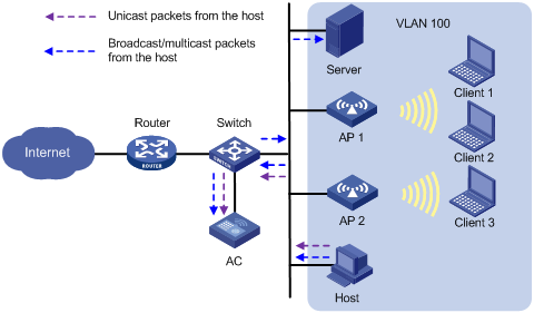
As shown in Figure 4, the AC centrally forwards the client traffic. Enable user isolation on the AC for VLAN 100.
· The host sends broadcast or multicast packets in VLAN 100. The server and AC can receive the packets. When the AC receives the packets, it discards them instead of forwarding them to any APs in the WLAN.
· The host sends unicast packets to Client 3 in VLAN 100. When the AC receives the packets, it discards them instead of forwarding them to AP 2.
Figure 4 Packet forwarding path
User isolation mechanism in local forwarding mode (packets received from wireless users)
As shown in Figure 5, AP 1 performs local forwarding for clients. Enable user isolation on AP 1 for VLAN 100.
· Client 1 sends broadcast or multicast packets in VLAN 100.
¡ When AP 1 receives the packets, it forwards them to the server, AP 2, and the host in VLAN 100 through the wired port. However, AP 1 does not forward the packets to Client 2 because user isolation is enabled.
¡ When AP 2 receives the packets, it forwards them to Client 3 since user isolation is not enabled on AP 2.
· Client 1 sends unicast packets to Client 3 in VLAN 100. When AP 1 receives the packets, it discards them instead of forwarding them to AP 2.
Figure 5 Packet forwarding path
User isolation mechanism in local forwarding mode (packets received from wired users)
As shown in Figure 6, AP 1 performs local forwarding for clients. Enable user isolation on AP 1 for VLAN 100.
· The host sends broadcast or multicast packets in VLAN 100. The server, AC, AP 1, and AP 2 can receive the packets.
¡ When AP 1 receives the packets, it discards them instead of forwarding them to Client 1 and Client 2.
¡ When AP 2 receives the packets, it forwards them to Client 3 since user isolation is not enabled on AP 2.
· The host sends unicast packets to Client 1 in VLAN 100. When AP 1 receives the packets, it discards them instead of forwarding them to Client 1.
Figure 6 Packet forwarding path
Enabling SSID-based user isolation
1. Enter system view.
system-view
2. Enter service template view.
wlan service-template service-template-name
3. Enable SSID-based user isolation.
user-isolation enable
By default, SSID-based user isolation is disabled.
User isolation configuration examples
Example: Configuring SSID-based user isolation (centralized forwarding mode)
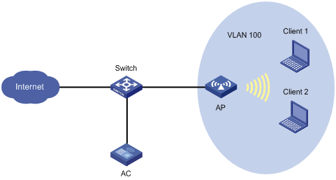
Network configuration
As shown in Figure 7, Client 1 and Client 2 use the same SSID to access the Internet. The AC centrally forwards the client traffic.
Configure user isolation on the AC to isolate the clients from each other while providing Internet access for the clients.
Procedure
# Configure Client 1 and Client 2 to access the Internet through service template service. For more information, see AP management and WLAN access in WLAN Configuration Guide. (Details not shown.)
# Enable SSID-based user isolation for service template service.
<AC> system-view
[AC] wlan service-template service
[AC-wlan-st-service] user-isolation enable
[AC-wlan-st-service] quit
Verifying the configuration
# Verify that Client 1 and Client 2 can use service service to access the Internet but cannot access each other. (Details not shown.)
Example: Configuring SSID-based user isolation (local forwarding mode)
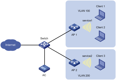
Network configuration
As shown in Figure 8, Client 1 and Client 2 use the same SSID to access the Internet. The APs perform local traffic forwarding.
Configure user isolation for AP 1 to isolate the clients from each other while providing Internet access for the clients.
Procedure
# Configure Client 1 and Client 2 to access the Internet through service template service1. Configure the APs to perform local traffic forwarding for the clients. For more information, see AP management and WLAN access in WLAN Configuration Guide. (Details not shown.)
# Enable SSID-based user isolation for service template service1.
<AC> system-view
[AC] wlan service-template service1
[AC-wlan-st-service1] user-isolation enable
[AC-wlan-st-service1] quit
Verifying the configuration
# Verify that Client 1 and Client 2 can use service service1 to access the Internet but cannot access each other. (Details not shown.)