- Table of Contents
-
- 02-WLAN Configuration Guides
- 00-Preface
- 01-AP management configuration
- 02-Radio management configuration
- 03-WLAN access configuration
- 04-WLAN security configuration
- 05-WLAN authentication configuration
- 06-WIPS configuration
- 07-WLAN QoS configuration
- 08-WLAN roaming configuration
- 09-WLAN load balancing configuration
- 10-WLAN radio resource measurement configuration
- 11-Channel scanning configuration
- 12-Band navigation configuration
- 13-WLAN high availability configuration
- 14-802.11r configuration
- 15-Wireless location configuration
- 16-AC hierarchy configuration
- 17-WLAN RRM configuration
- 18-WLAN IP snooping configuration
- 19-WLAN probe configuration
- 20-Spectrum management configuration
- 21-WLAN radio load balancing configuration
- 22-User isolation configuration
- 23-Packet capture configuration
- 24-802.1X client configuration
- 25-IP source guard configuration
- Related Documents
-
| Title | Size | Download |
|---|---|---|
| 16-AC hierarchy configuration | 380.37 KB |
Contents
AC hierarchy operating mechanism··
Configuring parameters for local AC and central AC communication on a local AC
Display and maintenance commands for AC hierarchy
AC hierarchy configuration examples
Example: Configuring AC hierarchy
Example: Configuring access right management
Configuring AC hierarchy
About AC hierarchy
AC hierarchy provides a centralized management method for ACs that run the Comware 7 software version. This simplifies WLAN maintenance and improves WLAN expandability.
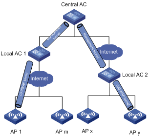
AC hierarchy architecture
An AC hierarchy network contains a central AC, local ACs, and APs. The central AC manages all local ACs, and local ACs provide network access to APs and process client traffic.
AC hierarchy uses the following tunnels for local AC and AP management:
· Tunnels between the central AC and local ACs—The central AC sends AP configuration over this tunnel to the local ACs, and the local ACs report AP and client information to the central AC.
· CAPWAP tunnels between local ACs and APs—Local ACs send AP configuration to the APs over this tunnel.
Figure 1 AC hierarchy architecture
AC hierarchy operating mechanism
Figure 2 AC hierarchy operating mechanism
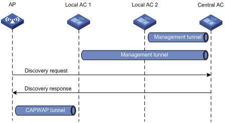
As shown in Figure 2, AC hierarchy operates as follows:
1. Each local AC establishes a management tunnel with the central AC.
2. The AP sends a discovery request to the central AC.
3. The central AC sends a discovery response to the AP. The response contains the IP address of the local AC that has the lowest workload.
4. The AP sends a discovery request to the assigned local AC to establish a CAPWAP tunnel with the local AC.
During tunnel establishment, the local AC requests for AP validity from the central AC and it establishes a tunnel with the AP only when the AP is valid. The AP is valid if the central AC has the manual AP setting for the AP or auto AP is enabled on the central AC. For more information, see "Managing APs."
5. The local AC reports the AP up event to the central AC.
Data forwarding
In an AC hierarchy network, you can configure either local ACs or APs to perform data forwarding.
For more information about data forwarding, see "Configuring WLAN access."
Roaming
The roaming method for a client in an AC hierarchy network depends on the authenticator of the client. If the local AC to which the client is associated is the authenticator, the roaming method is the same as that in an AC + fit AP network. If the central AC is the authenticator, roaming entries are generated on both the central AC and the local AC. Then, the client can perform intra- or inter-local AC roaming.
For more information about the client authenticator, see "Configuring WLAN authentication." For more information about roaming, see "Configuring WLAN roaming."
Access right management
Access right management allows you to assign different rights to administrators for the central AC and local ACs by configuring location identifiers for service templates, AP groups, and RRM holddown groups.
An administrator can view and manage only service templates, AP groups, or RRM holddown groups whose location identifiers are accessible to his or her user role from both the CLI and the Web interface. The super user named admin can manage all service templates, AP groups, and RRM holddown groups. The default location identifier default-location is accessible to all user roles and cannot be deleted.
Configuring parameters for local AC and central AC communication on a local AC
About configuring parameters for local AC and central AC communication
Perform this task to configure an AC as a local AC to establish a management tunnel with the specified central AC.
Restrictions and guidelines
You can specify a maximum of three IPv4 addresses and three IPv6 addresses of central ACs.
Procedure
1. Enter system view.
system-view
2. Enable local AC.
wlan local-ac enable
By default, local AC is disabled.
3. Specify a central AC for the local AC.
wlan central-ac { ip ipv4-address | ipv6 ipv6-address }
By default, no central AC is specified for a local AC.
4. Specify a VLAN that the local AC uses to establish a tunnel with the central AC.
wlan local-ac capwap source-vlan vlan-id
By default, a local AC uses VLAN 1 to establish a tunnel with the central AC.
Display and maintenance commands for AC hierarchy
Execute display commands in any view.
|
Task |
Command |
|
Display the current AC role. |
display wlan ac-role |
|
Display client information. |
display wlan client distributed-sys [ verbose ] |
|
Display local AC information on the local AC. |
display wlan local-ac |
|
Display local AC connection records on the central AC. |
display wlan local-ac { all | name local-ac-name } connection-record |
|
Display information about files and folders on a local AC. |
display wlan local-ac name local-ac-name files |
|
Display the online duration of an online local AC on the central AC. |
display wlan local-ac { all | name local-ac-name } online-time |
|
Reboot the specified local AC or all local ACs. |
reset wlan local-ac { all | name ac-name } |
AC hierarchy configuration examples
In an AC hierarchy network, the device can only act as a local AC.
Example: Configuring AC hierarchy
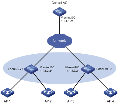
Network configuration
As shown in Figure 3, configure AC hierarchy to enable the central AC to perform client authentication and the local ACs to forward client traffic.
Procedure
1. Configure DHCP on local ACs to assign the central AC's IP address and APs' IP addresses to APs. (Details not shown.)
2. Configure the central AC:
# Create local AC localac1.
<CentralAC> system-view
[CentralAC] wlan local-ac name localac1 model WX3540H
[CentralAC-wlan-local-ac-localac1] serial-id 210235A1BSC123000050
[CentralAC-wlan-local-ac-localac1] quit
# Create local AC localac2.
[CentralAC] wlan local-ac name localac2 model WX3540H
[CentralAC-wlan-local-ac-localac2] serial-id 210235A1BSC124000060
[CentralAC-wlan-local-ac-localac2] quit
# Create manual AP ap1, and specify the AP model and serial ID.
[CentralAC] wlan ap ap1 model WA4320H
[CentralAC-wlan-ap-ap1] serial-id 219801A0YG8165E00001
# Enable AC rediscovery.
[CentralAC-wlan-ap-ap1] control-address enable
[CentralAC-wlan-ap-ap1] quit
# Create manual AP ap2, and specify the AP model and serial ID.
[CentralAC] wlan ap ap2 model WA4320H
[CentralAC-wlan-ap-ap2] serial-id 219801A0CNC125002328
# Enable AC rediscovery.
[CentralAC-wlan-ap-ap2] control-address enable
[CentralAC-wlan-ap-ap2] quit
# Create manual AP ap3, and specify the AP model and serial ID.
[CentralAC] wlan ap ap3 model WA4320H
[CentralAC-wlan-ap-ap3] serial-id 219801A0CNC125002327
# Enable AC rediscovery.
[CentralAC-wlan-ap-ap3] control-address enable
[CentralAC-wlan-ap-ap3] quit
# Create manual AP ap4, and specify the AP model and serial ID.
[CentralAC] wlan ap ap4 model WA4320H
[CentralAC-wlan-ap-ap4] serial-id 219801A0CNC125002326
# Enable AC rediscovery.
[CentralAC-wlan-ap-ap4] control-address enable
[CentralAC-wlan-ap-ap4] quit
# Create VLAN-interface 100 and assign an IP address to it.
[CentralAC] interface vlan-interface 100
[CentralAC-Vlan-interface100] ip address 1.1.1.1 24
[CentralAC-Vlan-interface100] quit
3. Configure local AC 1:
# Create VLAN-interface 100, and assign an IP address to it.
<LocalAC1> system-view
[LocalAC1] interface vlan-interface 100
[LocalAC1-Vlan-interface100] ip address 1.1.1.2 24
[LocalAC1-Vlan-interface100] quit
# Enable local AC.
[LocalAC1] wlan local-ac enable
# Specify a central AC for the local AC.
[LocalAC1] wlan central-ac ip 1.1.1.1
4. Configure local AC 2:
# Create VLAN-interface 100, and assign an IP address to it.
<LocalAC2> system-view
[LocalAC2] interface vlan-interface 100
[LocalAC2-Vlan-interface100] ip address 1.1.1.3 24
[LocalAC2-Vlan-interface100] quit
# Enable local AC.
[LocalAC2] wlan local-ac enable
# Specify a central AC for the local AC.
[LocalAC2] wlan central-ac ip 1.1.1.1
Verifying the configuration
# On the central AC, verify that each local AC has established a CAPWAP tunnel with the central AC.
[CentralAC] display wlan local-ac all
Total number of local ACs: 2
Total number of connected local ACs: 2
Local AC Information
State : I = Idle, J = Join, JA = JoinAck, IL = ImageLoad
C = Config, DC = DataCheck, R = Run
AC name ACID State Model Serial ID
localac1 1 R WX3540H 210235A1BSC123000050
localac2 2 R WX3540H 210235A1BSC124000060
# On local AC 1, verify that local AC 1 has established a CAPWAP tunnel with the central AC.
[LocalAC1] display wlan local-ac
Local AC Information:
Model : WX3540H
Serial ID : 210235A1BSC123000050
MAC address : 5866-BA20-6E60
Local AC address : 1.1.1.2
H/W version : Ver.A
S/W version : c5419
Static central AC IPv4 address: 1.1.1.1
Static central AC IPv6 address: Not configured
Central AC Information:
Central AC address : 1.1.1.1
State : Run
Sent control packets : 6088
Received control packets : 6092
# On local AC 2, verify that local AC 2 has established a CAPWAP tunnel with the central AC. (Details not shown.)
# Verify that AP 1, AP 2, AP 3, and AP 4 have come online.
[CentralAC] display wlan ap all
Total number of APs: 1
Total number of connected APs: 1
Total number of connected configured APs: 1
Total number of connected auto APs: 0
Total number of connected anchor APs: 0
Maximum supported APs: 3072
Remaining APs: 3071
Fit APs activated by license: 128
Remaining fit APs: 127
WTUs activated by license: 0
Remaining WTUs: 0
AP information
State : I = Idle, J = Join, JA = JoinAck, IL = ImageLoad
C = Config, DC = DataCheck, R = Run, M = Master, B = Backup
AP name APID State Model Serial ID
ap1 1 R/M WA4320H 219801A0YG8165E00001
Example: Configuring access right management
Network configuration
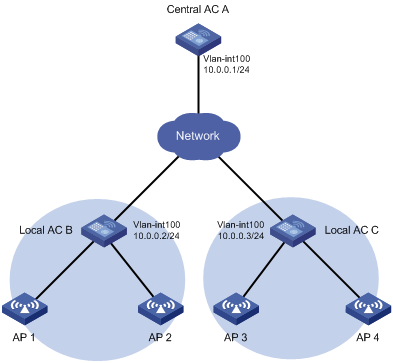
As shown in Figure 4, configure access right management to meet the following requirements:
· The administrators for local AC B and local AC C can manage the APs in areas B and C, respectively.
· The administrator for the central AC can manage all APs.
Procedure
1. Configure DHCP on the local ACs to assign the central AC's IP address and APs' IP addresses to the APs. (Details not shown.)
2. Configure the central AC:
# Enable the Telnet server and AAA authentication.
<CentralAC> system-view
[CentralAC] telnet server enable
[CentralAC] line vty 0 5
[CentralAC] line class vty
[CentralAC] authentication-mode scheme
# Create local AC localac-b, and specify the AC model and serial ID.
[CentralAC] wlan local-ac name localac-b model WX3520H
[CentralAC-wlan-local-ac-localac-b] serial-id 210235A1BSC123000050
[CentralAC-wlan-local-ac-localac-b] quit
# Create local AC localac-c, and specify the AC model and serial ID.
[CentralAC] wlan local-ac name localac-c model WX3520H
[CentralAC-wlan-local-ac-localac-c] serial-id 210235A1BSC123000051
[CentralAC-wlan-local-ac-localac-c] quit
# Create manual AP ap1, and specify the AP model and serial ID.
[CentralAC] wlan ap ap1 model WA4320H
[CentralAC-wlan-ap-ap1] serial-id 219801A0YG8165E00001
# Enable AC rediscovery.
[CentralAC-wlan-ap-ap1] control-address enable
[CentralAC-wlan-ap-ap1] quit
# Configure AP 2, AP 3, and AP 4 in the same way AP 1 is configured. (Details not shown.)
# Create VLAN-interface 100 and assign an IP address to it.
[CentralAC] interface vlan-interface 100
[CentralAC-Vlan-interface100] ip address 10.0.0.1 24
[CentralAC-Vlan-interface100] quit
# Create location identifiers areab and areac.
[CentralAC] wlan location areab
[CentralAC] wlan location areac
# Create user role b.
[CentralAC] role name b
# Configure an XML element rule and a Web menu rule.
[CentralAC-role-b] rule 1 permit read write execute xml-element
[CentralAC-role-b] rule 2 permit read write execute web-menu
# Configure location identifier areab to be accessible to user role b.
[CentralAC-role-b] location policy deny
[CentralAC-role-b-locationpolicy] permit location areab
[CentralAC-role-b-locationpolicy] quit
[CentralAC-role-b] quit
# Create user role c.
[CentralAC] role name c
# Configure an XML element rule and a Web menu rule.
[CentralAC-role-c] rule 1 permit read write execute xml-element
[CentralAC-role-c] rule 2 permit read write execute web-menu
# Configure location identifier areac to be accessible to user role c.
[CentralAC-role-c] location policy deny
[CentralAC-role-c-locationpolicy] permit location areac
[CentralAC-role-c-locationpolicy] quit
[CentralAC-role-c] quit
# Add local user admin.
[CentralAC] local-user admin
# Authorize user admin to use HTTP and HTTPS services.
[CentralAC-luser-manage-admin] service-type http https
[CentralAC-luser-manage-admin] quit
# Add local user b-admin.
[CentralAC] local-user b-admin
# Authorize user b-admin to use HTTP and HTTPS services.
[CentralAC-luser-manage-b-admin] service-type http https
# Configure a password for the user.
[CentralAC-luser-manage-b-admin] password simple badmin
# Assign user role b to user b-admin as the authorized user role.
[CentralAC-luser-manage-b-admin] authorization-attribute user-role b
# Delete the default user role.
[CentralAC-luser-manage-b-admin] undo authorization-attribute user-role network-operator
[CentralAC-luser-manage-b-admin] quit
# Add local user c-admin.
[CentralAC] local-user c-admin
# Authorize user c-admin to use HTTP and HTTPS services.
[CentralAC-luser-manage-c-admin] service-type http https
# Configure a password for the user.
[CentralAC-luser-manage-c-admin] password simple cadmin
# Assign user role c to user c-admin.
[CentralAC-luser-manage-c-admin] authorization-attribute user-role c
# Delete the default user role.
[CentralAC-luser-manage-c-admin] undo authorization-attribute user-role network-operator
[CentralAC-luser-manage-c-admin] quit
# Create AP group groupb, and add AP 1 and AP 2 to the AP group.
[CentralAC] wlan ap-group groupb
[CentralAC-wlan-ap-group-groupb] ap ap1 ap2
# Specify location identifier areab for the AP group.
[CentralAC-wlan-ap-group-groupb] location areab
[CentralAC-wlan-ap-group-groupb] quit
# Create AP group groupc, and add AP 3 and AP 4 to the AP group.
[CentralAC] wlan ap-group groupc
[CentralAC-wlan-ap-group-groupc] ap ap3 ap4
# Specify location identifier areac for the AP group.
[CentralAC-wlan-ap-group-groupc] location areac
[CentralAC-wlan-ap-group-groupc] quit
3. Configure local AC B:
# Create VLAN-interface 100, and assign an IP address to it.
<LocalAC-B> system-view
[LocalAC-B] interface vlan-interface 100
[LocalAC-B-Vlan-interface100] ip address 10.0.0.2 24
[LocalAC-B-Vlan-interface100] quit
# Enable local AC.
[LocalAC-B] wlan local-ac enable
# Specify a central AC for the local AC.
[LocalAC-B] wlan central-ac ip 10.0.0.1
4. Configure local AC C:
# Create VLAN-interface 100, and assign an IP address to it.
<LocalAC-C> system-view
[LocalAC-C] interface vlan-interface 100
[LocalAC-C-Vlan-interface100] ip address 10.0.0.3 24
[LocalAC-C-Vlan-interface100] quit
# Enable local AC.
[LocalAC-C] wlan local-ac enable
# Specify a central AC for the local AC.
[LocalAC-C] wlan central-ac ip 10.0.0.1
Verifying the configuration
# Use super username admin to log in to the central AC from the Web interface through Telnet.
# Verify that you can view and manage all APs.
Figure 5 Super user page view
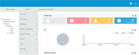
# Use local username c-admin to log in to the central AC from the Web interface.
# Verify that you can view and manage only APs in area C.
Figure 6 User c-admin page view
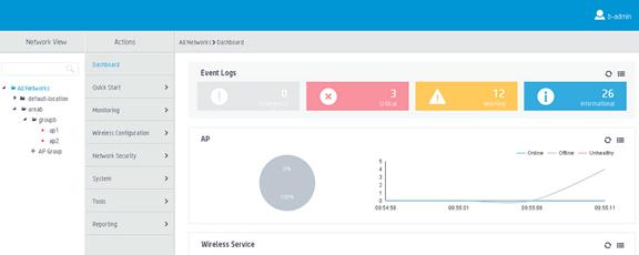
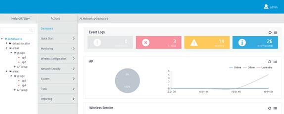
# Use local username b-admin to log in to the central AC from the Web interface.
# Verify that you can view and manage only APs in area B.
Figure 7 User b-admin page view