- Table of Contents
-
- 11-Network Management and Monitoring Configuration Guide
- 00-Preface
- 01-System maintenance and debugging configuration
- 02-NTP configuration
- 03-PTP configuration
- 04-Information center configuration
- 05-SNMP configuration
- 06-RMON configuration
- 07-NQA configuration
- 08-Mirroring configuration
- 09-sFlow configuration
- 10-Process monitoring and maintenance configuration
- 11-EAA configuration
- 12-CWMP configuration
- 13-NETCONF configuration
- 14-Packet capture configuration
- Related Documents
-
| Title | Size | Download |
|---|---|---|
| 12-CWMP configuration | 487.62 KB |
Configuring the preferred ACS attributes
Configuring the default ACS attributes from the CLI
Configuring ACS authentication parameters
Configuring the provision code
Configuring the CWMP connection interface
Configuring autoconnect parameters
Enabling NAT traversal for the CPE
Specifying an SSL client policy for HTTPS connection to ACS
Displaying and maintaining CWMP
Configuring CWMP
Overview
CPE WAN Management Protocol (CWMP), also called "TR-069," is a DSL Forum technical specification for remote management of home network devices.
The protocol was initially designed to provide remote autoconfiguration through a server for large numbers of dispersed end-user devices in DSL networks. However, it has been increasingly used on other types of networks, including Ethernet, for remote autoconfiguration.
CWMP network framework
Figure 1 shows a basic CWMP network framework.
Figure 1 CWMP network framework
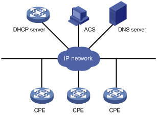
A basic CWMP network includes the following network elements:
· ACS—Autoconfiguration server, the management device in the network.
· CPE—Customer premises equipment, the managed device in the network.
· DNS server—Domain name system server. CWMP defines that the ACS and the CPE use URLs to identify and access each other. DNS is used to resolve the URLs.
· DHCP server—Assigns ACS attributes along with IP addresses to CPEs when the CPEs are powered on. DHCP server is optional in CWMP. With a DHCP server, you do not need to configure ACS attributes manually on each CPE. The CPEs contact the ACS automatically when they are powered on for the first time.
The device is operating as a CPE in the CWMP framework.
Basic CWMP functions
The ACS identifies different categories of CPEs by provision code. You can use the ACS to autoconfigure and upgrade each category of CPEs in bulk.
Autoconfiguration
You can create configuration files for different categories of CPEs on the ACS. The ACS identifies the configuration file for a CPE by its provision code.
The following are methods available for the ACS to issue configuration to the CPE:
· Transfers the configuration file to the CPE, and specifies the file as the next-startup configuration file. At a reboot, the CPE starts up with the ACS-specified configuration file.
· Runs the configuration in the CPE's RAM. The configuration takes effect immediately on the CPE. For the running configuration to survive a reboot, you must save the configuration on the CPE.
Software image management
The ACS can manage CPE software upgrade.
When the ACS finds a software version update, the ACS notifies the CPE to download the software image file from a specific location. The location can be the URL of the ACS or an independent file server.
The CPE notifies the ACS of the download result (success or failure) when it completes a download attempt. The CPE downloads the specified image file only when the file passes validity verification.
Data backup
The ACS can require the CPE to upload a configuration or log file to a specific location. The destination location can be the ACS or a file server.
Status and performance monitoring
The CPE allows the ACS to monitor the status and performance objects in Table 1.
Table 1 CPE status and performance objects available for the ACS to monitor
|
Category |
Objects |
|
Device information |
Manufacturer ManufacturerOUI SerialNumber HardwareVersion SoftwareVersion |
|
Operating status and information |
DeviceStatus UpTime |
|
Configuration file |
ConfigFile |
|
CWMP settings |
ACS URL ACS username ACS password PeriodicInformEnable PeriodicInformInterval PeriodicInformTime ConnectionRequestURL (CPE URL) ConnectionRequestUsername (CPE username) ConnectionRequestPassword (CPE password) |
How CWMP works
CWMP uses remote procedure call (RPC) methods for bidirectional communication between CPE and ACS. The RPC methods are encapsulated in HTTP or HTTPS.
RPC methods
Table 2 shows the primary RPC methods used in CWMP.
|
RPC method |
Description |
|
Get |
The ACS obtains the values of parameters on the CPE. |
|
Set |
The ACS modifies the values of parameters on the CPE. |
|
Inform |
The CPE sends an Inform message to the ACS for the following purposes: · Initiates a connection to the ACS. · Reports configuration changes to the ACS. · Periodically updates CPE settings to the ACS. |
|
Download |
The ACS requires the CPE to download a configuration or software image file from a specific URL for software or configuration update. |
|
Upload |
The ACS requires the CPE to upload a file to a specific URL. |
|
Reboot |
The ACS reboots the CPE remotely for the CPE to complete an upgrade or recover from an error condition. |
Autoconnect between ACS and CPE
The CPE connects to the ACS automatically after it obtains the DNS server address and basic ACS parameters (ACS URL and authentication username and password). You can configure this information manually on the CPE, through a DHCP server, or through the ACS.
After establishing a connection, the ACS can issue configuration and software images to the CPE. If the connection is disconnected before a session is complete, the CPE retries the failed connection automatically. The retry attempt continues until the connection is established again or the specified retry limit is reached.
Depending on the configuration, the CPE can also connect to the ACS regularly or at a scheduled time to update its information with the ACS.
|
|
NOTE: For the CPE to complete autoconfiguration at its initial startup, H3C recommends that you use a DHCP server. The DHCP option for ACS parameter assignment is option 43. For more information about DHCP, see Layer 3—IP Services Configuration Guide. |
CWMP connection establishment
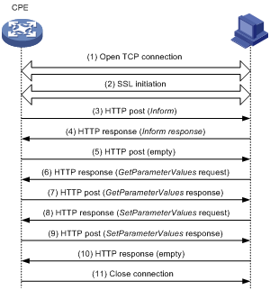
As shown in Figure 2, the CPE and the ACS use the following process to establish a connection:
1. After obtaining the basic ACS parameters, the CPE initiates a TCP connection to the ACS.
2. If HTTPS is used, the CPE and the ACS initialize SSL for a secure HTTP connection.
3. The CPE sends an Inform message in HTTPS to initiate a CWMP session.
4. After the CPE passes authentication, the ACS returns an Inform response to establish the session.
5. After sending all requests, the CPE sends an empty HTTP post message.
6. If the ACS wants to point the CPE to a new ACS URL, the ACS queries the ACS URL set on the CPE.
7. The CPE replies with its ACS URL setting.
8. The ACS sends a Set request to modify the ACS URL on the CPE.
9. After the ACS URL is modified, the CPE sends a response.
10. The ACS sends an empty HTTP message to notify the CPE that it has no other requests.
11. The CPE closes the connection, and then initiates a new connection to the new ACS URL.
Figure 2 CWMP message interaction procedure
Configuration task list
To use CWMP, you must enable CWMP from the CLI. You can then configure ACS and CPE attributes from the CPE's CLI, the DHCP server, or the ACS.
For an attribute, the CLI- and ACS-assigned values have higher priority than the DHCP-assigned value. The CLI- and ACS-assigned values overwrite each other, whichever is assigned later.
This document only describes configuring ACS and CPE attributes from the CLI and DHCP server. For more information about configuring and using the ACS, see ACS documentation.
To configure CWMP, perform the following tasks:
Enabling CWMP from the CLI
You must enable CWMP for other CWMP settings to take effect, whether they are configured from the CLI, or assigned through the DHCP server or ACS.
To enable CWMP:
|
Command |
Remarks |
|
|
1. Enter system view. |
N/A |
|
|
2. Enter CWMP view. |
N/A |
|
|
3. Enable CWMP. |
By default, CWMP is disabled. |
Configuring ACS attributes
You can configure two sets of ACS attributes for the CPE: preferred and default.
· The preferred ACS attributes are configurable from the CPE's CLI, the DHCP server, and ACS. For an attribute, the CLI- and ACS-assigned values have higher priority than the DHCP-assigned value. The CLI- and ACS-assigned values overwrite each other.
· The default ACS attributes are configurable only from the CLI.
The CPE uses the default ACS attributes for connection establishment only when it is not assigned a preferred ACS URL from the CLI, ACS, or DHCP server.
Configuring the preferred ACS attributes
Assigning ACS attributes from the DHCP server
You can use DHCP option 43 to assign the ACS URL and ACS login authentication username and password.
If the DHCP server is an H3C device, you can configure DHCP option 43 by using the option 43 hex 01length URL username password command.
· length—A hexadecimal number that indicates the total length of the length, URL, username, and password arguments, including the spaces between these arguments. No space is allowed between the 01 keyword and the length value.
· URL—ACS URL.
· username—Username for the CPE to authenticate to the ACS.
· password—Password for the CPE to authenticate to the ACS.
|
|
NOTE: The ACS URL, username and password must use the hexadecimal format and be space separated. |
The following example configures the ACS address as http://169.254.76.31:7547/acs, username as 1234, and password as 5678:
[Sysname] dhcp server ip-pool 0
[Sysname-dhcp-pool-0] option 43 hex 0127687474703A2F2F3136392E3235342E37362E33313A373534372F61637320313233342035363738
Table 3 Hexadecimal forms of the ACS attributes
|
Attribute |
Attribute value |
Hexadecimal form |
|
Length |
39 characters |
27 |
|
ACS URL |
http://169.254.76.31/acs |
687474703A2F2F3136392E3235342E37362E33313A373534372F61637320 NOTE: The two ending digits (20) represent the space. |
|
ACS connect username |
1234 |
3132333420 NOTE: The two ending digits (20) represent the space. |
|
ACS connect password |
5678 |
35363738 |
For more information about DHCP and DHCP Option 43, see layer 3—IP Services Configuration Guide.
Configuring the preferred ACS attributes from the CLI
|
Step |
Command |
Remarks |
|
1. Enter system view. |
system-view |
N/A |
|
2. Enter CWMP view. |
cwmp |
N/A |
|
3. Configure the preferred ACS URL. |
cwmp acs url url |
By default, no preferred ACS URL has been configured. |
|
4. Configure the username for authentication to the preferred ACS URL. |
cwmp acs username username |
By default, no username has been configured for authentication to the preferred ACS URL. |
|
5. (Optional.) Configure the password for authentication to the preferred ACS URL. |
cwmp acs password { cipher | simple } password |
By default, no password has been configured for authentication to the preferred ACS URL. |
Configuring the default ACS attributes from the CLI
|
Step |
Command |
Remarks |
|
1. Enter system view. |
system-view |
N/A |
|
2. Enter CWMP view. |
cwmp |
N/A |
|
3. Configure the default ACS URL. |
cwmp acs default url url |
By default, no default ACS URL has been configured. |
|
4. Configure the username for authentication to the default ACS URL. |
cwmp acs default username username |
By default, no username has been configured for authentication to the default ACS URL. |
|
5. (Optional.) Configure the password for authentication to the default ACS URL. |
cwmp acs default password { cipher | simple } password |
By default, no password has been configured for authentication to the default ACS URL. |
Configuring CPE attributes
You can assign CPE attribute values to the CPE from the CPE's CLI or the ACS. The CLI- and ACS-assigned values overwrite each other, whichever is assigned later.
For more information about the configuration methods supported for each CPE attribute, see "Configuration task list."
Configuring ACS authentication parameters
To protect the CPE against unauthorized access, configure a CPE username and password for ACS authentication. When an ACS initiates a connection to the CPE, the ACS must provide the correct username and password.
|
|
NOTE: The password setting is optional. You may choose to use only a username for authentication. |
To configure ACS authentication parameters:
|
Step |
Command |
Remarks |
|
1. Enter system view. |
system-view |
N/A |
|
2. Enter CWMP view. |
cwmp |
N/A |
|
3. Configure the username for authentication to the CPE. |
cwmp cpe username username |
By default, no username has been configured for authentication to the CPE. |
|
4. (Optional.) Configure the password for authentication to the CPE. |
cwmp cpe password { cipher | simple } password |
By default, no password has been configured for authentication to the CPE. |
Configuring the provision code
The ACS uses the provision code to identify services assigned to each CPE. For correct configuration deployment, make sure the same provision code is configured on the CPE and the ACS.
To configure the provision code:
|
Step |
Command |
Remarks |
|
1. Enter system view. |
system-view |
N/A |
|
2. Enter CWMP view. |
cwmp |
N/A |
|
3. Configure the provision code. |
cwmp cpe provision-code provision-code |
The default provision code is PROVISIONINGCODE. |
Configuring the CWMP connection interface
The CWMP connection interface is the interface that the CPE uses to communicate with the ACS. To establish a CWMP connection, the CPE sends the IP address of this interface in the Inform messages, and the ACS replies to this IP address.
Typically, the CPE selects the CWMP connection interface automatically.
If the interface that connects the CPE to the ACS is the only Layer 3 interface that has an IP address on the device, you do not need to specify the CWMP connection interface.
If the CPE has multiple Layer 3 interfaces, specify the interface that connects to the ACS as the CWMP connection interface. This manual setting avoids the risk of incorrect CWMP connection interface selection in an automatic selection process.
To configure the CWMP connection interface:
|
Step |
Command |
Remarks |
|
1. Enter system view. |
system-view |
N/A |
|
2. Enter CWMP view. |
cwmp |
N/A |
|
3. Specify the interface that connects to the ACS as the CWMP connection interface. |
cwmp cpe connect interface interface-type interface-number |
No CWMP connection interface is specified. |
Configuring autoconnect parameters
You can configure the CPE to connect to the ACS periodically, or at a schedule time for configuration or software update. To protect system resources, limit the number of retries that the CPE can make to connect to the ACS.
Configuring the periodic Inform feature
To connect to the ACS periodically for CPE information update:
|
Step |
Command |
Remarks |
|
1. Enter system view. |
system-view |
N/A |
|
2. Enter CWMP view. |
cwmp |
N/A |
|
3. Enable the periodic Inform feature. |
cwmp cpe inform interval enable |
By default, this function is disabled. |
|
4. (Optional.) Configure the Inform interval. |
cwmp cpe inform interval seconds |
By default, the CPE sends an Inform message to start a session every 600 seconds. |
Scheduling a connection initiation
To connect to the ACS for configuration or software update at a scheduled time:
|
Step |
Command |
Remarks |
|
1. Enter system view. |
system-view |
N/A |
|
2. Enter CWMP view. |
cwmp |
N/A |
|
3. Schedule a connection initiation. |
cwmp cpe inform time time |
By default, no connection initiation has been scheduled. |
Configuring the maximum number of connection retries
The CPE retries a connection automatically when one of the following events occurs:
· The CPE fails to connect to the ACS.
· The connection is disconnected before the session on the connection is completed.
The CPE considers a connection attempt as having failed when the close-wait timer expires. This timer starts when the CPE sends an Inform request. If the CPE fails to receive a response before the timer expires, the CPE resends the Inform request.
To configure the maximum number of connection retries that the CPE can make:
|
Step |
Command |
Remarks |
|
1. Enter system view. |
system-view |
N/A |
|
2. Enter CWMP view. |
cwmp |
N/A |
|
3. Configure the maximum number of connection retries. |
cwmp cpe connect retry times |
By default, the CPE retries a failed connection until the connection is established. |
Configuring the close-wait timer
The close-wait timer specifies the amount of time the connection to the ACS can be idle before it is terminated. The CPE terminates the connection to the ACS if no traffic is transmitted before the timer expires.
The timer also specifies the maximum amount of time the CPE waits for the response to a session request. The CPE determines that its session attempt has failed when the timer expires.
To configure the close-wait timer for the CPE:
|
Step |
Command |
Remarks |
|
1. Enter system view. |
system-view |
N/A |
|
2. Enter CWMP view. |
cwmp |
N/A |
|
3. Set the close-wait timer. |
cwmp cpe wait timeout seconds |
By default, the close-wait timer is 30 seconds. |
Enabling NAT traversal for the CPE
For the connection request initiated from the ACS to reach the CPE, you must enable NAT traversal feature on the CPE when a NAT gateway resides between the CPE and the ACS.
The NAT traversal feature complies with RFC 3489 Simple Traversal of UDP Through NATs (STUN). The feature enables the CPE to discover the NAT gateway, and obtain an open NAT binding (a public IP address and port binding) through which the ACS can send unsolicited packets. The CPE sends the binding to the ACS when it initiates a connection to the ACS. For the connection requests sent by the ACS at any time to reach the CPE, the CPE maintains the open NAT binding.
To enable NAT traversal on the CPE:
|
Step |
Command |
Remarks |
|
1. Enter system view. |
system-view |
N/A |
|
2. Enter CWMP view. |
cwmp |
N/A |
|
3. Enable NAT traversal. |
cwmp cpe stun enable |
By default, NAT traversal is disabled on the CPE. |
Specifying an SSL client policy for HTTPS connection to ACS
CWMP uses HTTP or HTTPS for data transmission. If the ACS uses HTTPS for secure access, its URL begins with https://. You must configure an SSL client policy for the CPE to authenticate the ACS for HTTPS connection establishment. For more information about configuring SSL client policies, see Security Configuration Guide.
To specify an SSL client policy for the CPE to establish an HTTPS connection to the ACS:
|
Step |
Command |
Remarks |
|
1. Enter system view. |
system-view |
N/A |
|
2. Enter CWMP view. |
cwmp |
N/A |
|
3. Specify an SSL client policy. |
ssl client-policy policy-name |
By default, no SSL client policy is specified. |
Displaying and maintaining CWMP
Execute display commands in any view.
|
Task |
Command |
|
Display CWMP configuration. |
display cwmp configuration |
|
Display the current status of CWMP. |
display cwmp status |
CWMP configuration example
Network requirements
As shown in Figure 3, use H3C IMC BIMS as the ACS to bulk-configure the devices (CPEs), and assign ACS attributes to the CPEs from the DHCP server.
The configuration files for the devices in equipment rooms A and B are configure1.cfg and configure2.cfg, respectively.
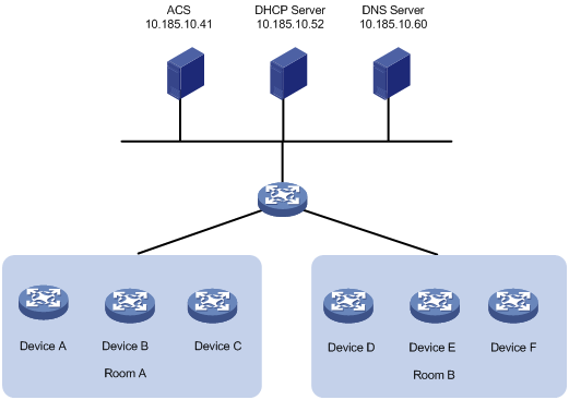
Table 4 shows the ACS attributes for the CPEs to connect to the ACS.
Table 4 ACS attributes
|
Item |
Setting |
|
Preferred ACS URL |
http://10.185.10.41:8080/acs |
|
ACS username |
Admin |
|
ACS password |
12345 |
Table 5 lists serial numbers of the CPEs.
|
Device |
Serial number |
|
Configuration procedure
Configuring the ACS
1. Log in to the ACS:
a. Launch a Web browser on the ACS configuration terminal.
b. In the address bar of the Web browser, enter the ACS URL and port number. This example uses http://10.185.10.41:8080/imc.
c. On the login page, enter the ACS login username and password, and then click Login.
2. Create a CPE user account:
a. Select Service > System Management > CPE Authentication User from the top navigation bar.
The CPE authentication user configuration page appears.
Figure 4 CPE authentication user configuration page
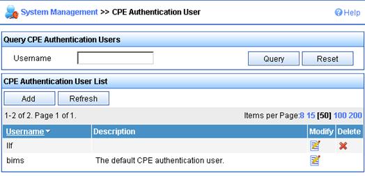
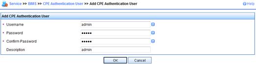
b. Click Add.
c. Enter the username and password for authentication to the ACS, and then click OK.
Figure 5 Adding a CPE user account
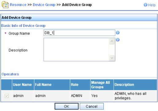
3. Add device groups and device classes for devices in equipment rooms A and B:
This example assigns all devices to the same device group, and assigns the devices in two equipment rooms to different device classes.
a. Select Service > Resource > Device Group from the top navigation bar.
b. Click Add.
c. On the Add Device Group page, enter a service group name (for example, DB_1), and then click OK.
Figure 6 Adding a device group
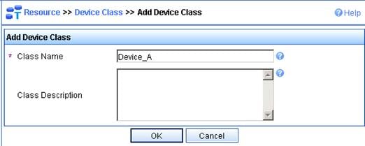
d. Select Service > Resource > Device Class from the top navigation bar.
e. Click Add.
f. On the Add Device Class page, enter a device class name for devices in equipment room A, and then click OK.
In this example, the device class for devices in equipment room A is Device_A.
Figure 7 Adding a device class
g. Repeat the previous two steps to create a device class for devices in equipment room B.
4. Add the devices as CPEs:
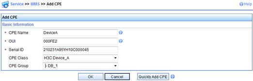
a. Select Service > BIMS > Add CPE from the top navigation bar.
b. On the Add CPE page, enter or select basic settings for device A, and then click OK.
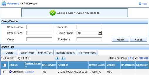
c. Repeat the previous two steps to add other devices.
After the CPE is added successfully, a success message is displayed, as shown in Figure 9.
Figure 9 CPE added successfully
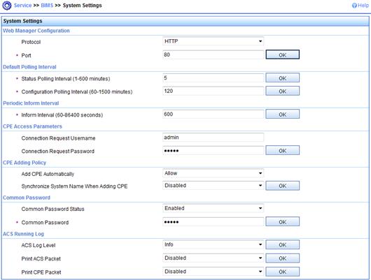
5. Configure the system settings of the ACS, as shown in Figure 10.
Figure 10 Configuring the system settings of the ACS
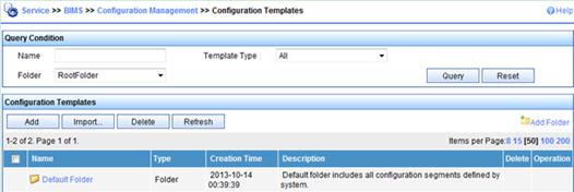
6. Add configuration templates and software library entries for the two classes of devices:
a. Select Service > BIMS > Configuration Management > Configuration Templates from the navigation tree.
Figure 11 Configuring templates page
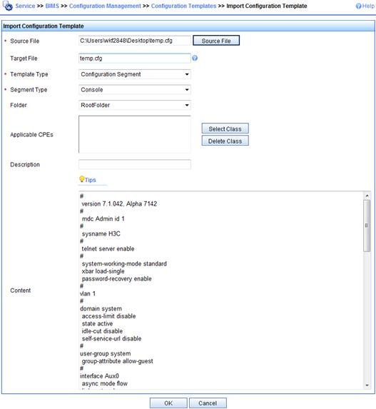
b. On the Configuration Templates page, click Import….
c. On the Import Configuration Template page, select configuration template settings for the Device_A device class, add the Device_A class to the Applicable CPEs pane, and then click OK.
d. Repeat the previous two steps to configure a configuration template for equipment room B's device class.
Figure 12 Importing configuration template
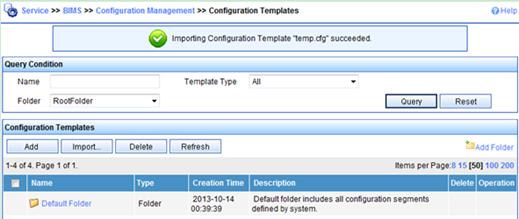
After the configuration template is added successfully, a success message is displayed, as shown in Figure 13.
Figure 13 Configuration templates
e. Select Service > BIMS > Configuration Management > Software Library from the top navigation bar.
Figure 14 Configuring software library
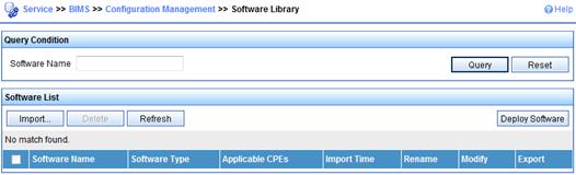
f. On the Software Library page, click Import….
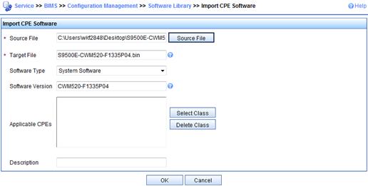
g. On the Import CPE Software page, select the software images for the Device_A device class, add the Device_A class to the Applicable CPEs pane, and then click OK.
h. Repeat the previous two steps to configure a software library entry for equipment room B's device class.
Figure 15 Importing CPE software
7. Add auto-deployment tasks:
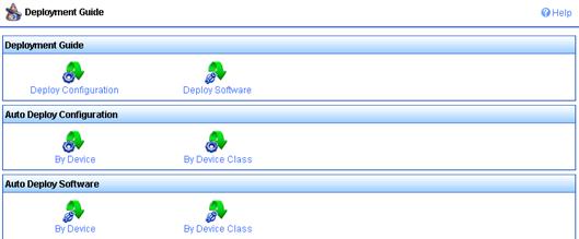
a. Select Service > BIMS > Configuration Management > Deployment Guide from the top navigation bar.
b. On the Deployment Guide page, click By Device Class in the Auto Deploy Configuration pane.
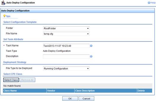
c. On the Auto Deploy Configuration page, click Select Class.
Figure 17 Configuring auto deployment
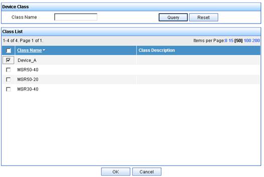
d. On the Device Class page, select Device_A, and then click OK.
Figure 18 Selecting device class
e. On the Auto Deploy Configuration page, click OK.
A success message is displayed, as shown in Figure 19.
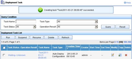
f. Add a deployment task for devices in equipment room B in the same way you add the deployment task for the devices in equipment room A.
Configuring the DHCP server
In this example, an H3C device is operating as the DHCP server.
1. Configure an IP address pool to assign IP addresses and DNS server address to the CPEs. This example uses subnet 10.185.10.0/24 for IP address assignment.
# Enable DHCP.
[DHCP_server] dhcp enable
# Enable DHCP server on VLAN-interface 1.
[DHCP_server] interface vlan-interface 1
[DHCP_server-Vlan-interface1] dhcp select server
[DHCP_server-Vlan-interface1] quit
# Exclude the DNS server address 10.185.10.60 and the ACS IP address 10.185.10.41 from dynamic allocation.
[DHCP_server] dhcp server forbidden-ip 10.185.10.41
[DHCP_server] dhcp server forbidden-ip 10.185.10.60
# Create DHCP address pool 0.
[DHCP_server] dhcp server ip-pool 0
# Assign subnet 10.185.10.0/24 to the address pool, and specify the DNS server address 10.185.10.60 in the address pool.
[DHCP_server-dhcp-pool-0] network 10.185.10.0 mask 255.255.255.0
[DHCP_server-dhcp-pool-0] dns-list 10.185.10.60
2. Configure DHCP Option 43 to contain the ACS URL, username, and password in hexadecimal format.
Configuring the DNS server
Map http://acs.database:9090/acs to http://10.185.1.41:9090/acs on the DNS server. For more information about DNS configuration, see DNS server documentation.
Connecting the CPEs to the network
# Connect the CPEs to the network, and then power on the CPEs. (Details not shown.)
At startup, the CPEs obtain the IP address and ACS information from the DHCP server to initiate a connection to the ACS. After the connection is established, the CPEs interact with the ACS to complete autoconfiguration.
Verifying the configuration
Verify that the CPEs have obtained the correct configuration file from the ACS:
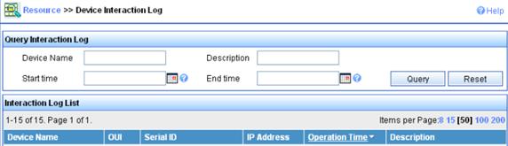
1. Select Service > Resource > Device Interaction Log from the top navigation bar.
2. On the Device Interaction Log page, verify that the configuration has been deployed on the CPEs.
Figure 20 Verifying the configuration deployment status