- Table of Contents
- Related Documents
-
| Title | Size | Download |
|---|---|---|
| 02-Login Management Configuration | 543.95 KB |
Logging in through the console port for the first time
Configuring console login control settings
Configuring none authentication for console login
Configuring password authentication for console login
Configuring scheme authentication for console login
Configuring common console user interface settings (optional)
Configuring none authentication for Telnet login
Configuring password authentication for Telnet login
Configuring scheme authentication for Telnet login
Configuring common VTY user interface settings (optional)
Using the device to log in to a Telnet server
Configuring the SSH server on the device
Using the device to log in to an SSH server
Displaying and maintaining CLI login
Logging in to the Web interface
Displaying and maintaining Web login
HTTP login configuration example
HTTPS login configuration example
Configuring SNMPv1 or SNMPv2c settings
Configuring source IP-based Telnet login control
Configuring source/destination IP-based Telnet login control
Configuring source MAC-based Telnet login control
Telnet login control configuration example
Configuring source IP-based SNMP login control
SNMP login control configuration example
Configuring source IP-based Web login control
Web login control configuration example
Login overview
This chapter describes the available login methods and introduces the related concepts.
Login methods at a glance
You can access the device by using the methods in Table 1.
|
Login method |
Default setting and configuration requirements |
|
|
|
||
|
By default, login through the console port is enabled, no username or password is required, and the user privilege level is 3. |
||
|
By default, Telnet service is enabled. · The IP address is 192.168.0.50. · The login username is admin. · The login password is h3capadmin. · The user privilege level is 3. |
||
|
By default, SSH service is disabled. To use SSH service, complete the following configuration tasks: · Enable the SSH server function and configure SSH attributes. · Assign an IP address to a Layer 3 interface and make sure the interface and the SSH client can reach each other. By default, the device has the IP address 192.168.0.50/24. · Configure scheme authentication for VTY login users (scheme authentication by default). · Configure the user privilege level of VTY login users (0 by default). |
||
|
By default, Web login is enabled. · The IP address is 192.168.0.50. · The login username is admin. · The login password is h3capadmin. · The user privilege level is 3. |
||
|
By default, SNMP login is disabled. To use SNMP service, complete the following configuration tasks: · Assign an IP address to a Layer 3 interface, and make sure the interface and the NMS can reach each other. By default, the device has the IP address 192.168.0.50. · Configure SNMP basic parameters. |
||
CLI user interfaces
The device uses user interfaces (also called "lines") to control CLI logins and monitor CLI sessions. You can configure access control settings, including authentication, user privilege, and login redirect on user interfaces. After users are logged in, their actions must be compliant with the settings on the user interfaces assigned to them.
Users are assigned different user interfaces, depending on their login methods, as shown in Table 2.
Table 2 CLI login method and user interface matrix
|
User interface |
Login method |
|
Console user interface |
Console port (EIA/TIA-232 DCE) |
|
Virtual type terminal (VTY) user interface |
Telnet or SSH |
User interface assignment
The device automatically assigns user interfaces to CLI login users, depending on their login methods. Each user interface can be assigned to only one user at a time. If no user interface is available, a CLI login attempt will be rejected. The maximum number of user interfaces varies by device.
For a CLI login, the device always picks the lowest numbered user interface from the idle user interfaces available for the type of login. For example, four VTY user interfaces (0 to 3) are configured, of which VTY 0 and VTY 3 are idle. When a user Telnets to the device, the device assigns VTY 0 to the user and uses the settings on VTY 0 to authenticate and manage the user.
User interface identification
A user interface can be identified by an absolute number, or the interface type and a relative number.
An absolute number uniquely identifies a user interface among all user interfaces. The user interfaces are numbered starting from 0 and incrementing by 1 and in the sequence of console and VTY user interfaces. You can use the display user-interface command without any parameters to view supported user interfaces and their absolute numbers.
A relative number uniquely identifies a user interface among all user interfaces that are the same type. The number format is user interface type + number. The user interfaces are numbered starting from 0 and incrementing by 1. For example, the first VTY user interface is VTY 0.
By default, you can access the CLI through the console port or Telnet.
The following matrix shows the supported console port types:
|
Hardware |
Console port |
|
WA4320-ACN |
Common console port |
|
WA4320H-ACN |
Mini USB port |
|
WA4320i-ACN |
Common console port |
|
WA4320-ACN-PI |
Not provided |
|
WA4620i-ACN/WA4620E-ACN |
Logging in through the console port for the first time
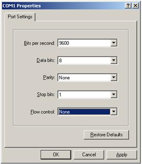
To log in through the console port, make sure the console terminal has a terminal emulation program (for example, HyperTerminal in Windows XP). In addition, the port settings of the terminal emulation program must be the same as the default settings of the console port in Table 3.
Table 3 Default console port properties
|
Parameter |
Default |
|
Bits per second |
9600 bps |
|
Flow control |
None |
|
Parity |
None |
|
Stop bits |
1 |
|
Data bits |
8 |
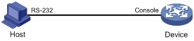
To log in through the console port from a console terminal (for example, a PC):
1. Connect the DB-9 female connector of the console cable to the serial port of the PC.
2. Connect the RJ-45 connector of the console cable to the console port of the device.
If the console port is a mini USB port, use a USB cable to connect a terminal to the console port.
|
|
IMPORTANT: · Identify the mark on the console port and make sure you are connecting to the correct port. · The serial ports on PCs do not support hot swapping. If the device has been powered on, always connect the console cable to the PC before connecting it to the device, and when you disconnect the cable, first disconnect it from the device. |
Figure 1 Connecting a terminal to the console port
3. If the PC is off, turn on the PC.
4. Launch the terminal emulation program and configure the communication properties on the PC.
Figure 2 through Figure 4 show the configuration procedure on Windows XP HyperTerminal. Make sure the port settings are the same as listed in Table 3.
On Windows Server 2003, add the HyperTerminal program first, and then log in to and manage the device as described in this document. On Windows Server 2008, Windows 7, Windows Vista, or some other operating system, obtain a third-party terminal control program first, and then follow the user guide or online help to log in to the device.
Figure 2 Connection description
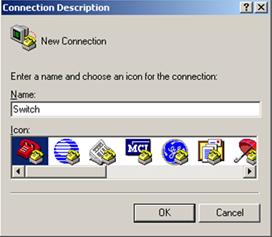
Figure 3 Specifying the serial port used to establish the connection
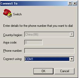
Figure 4 Setting the properties of the serial port
5. Power on the device and press Enter at the prompt.
The default user view prompt <WA4620i-ACN> appears. You can enter commands to configure or manage the device. To get help, enter ?.
Configuring console login control settings
The following authentication modes are available for controlling console logins:
· None—Requires no authentication. This mode is insecure.
· Password—Requires password authentication.
· Scheme—Uses the AAA module to provide local or remote console login authentication. You must provide a username and password to access the CLI. For more information about AAA, see Security Configuration Guide.
By default, console login does not require authentication. Any user can log in through the console port without authentication and have user privilege level 3. To improve device security, configure the password or scheme authentication mode immediately after you log in to the device for the first time.
Table 4 Configuration required for different console login authentication modes
|
Authentication mode |
Configuration tasks |
Reference |
|
None |
Set the authentication mode to none for the console user interface. |
|
|
Password |
Enable password authentication on the console user interface. Set a password. |
|
|
Scheme |
Enable scheme authentication on the console user interface. Configure local or remote authentication settings. To configure local authentication: 1. Configure a local user and specify the password. 2. Configure the device to use local authentication. To configure remote authentication: 1. Configure the RADIUS or HWTACACS scheme on the device. 2. Configure the username and password on the AAA server. 3. Configure the device to use the scheme for user authentication. |
Configuring none authentication for console login
|
Step |
Command |
Remarks |
|
1. Enter system view. |
system-view |
N/A |
|
2. Enter console user interface view. |
user-interface console first-number [ last-number ] |
N/A |
|
3. Enable none authentication mode. |
authentication-mode none |
By default, you can log in to the device through the console port without authentication and have user privilege level 3. |
|
4. Configure common settings for console login. |
See "Configuring common console user interface settings (optional)." |
Optional. |
The next time you attempt to log in through the console port, you do not need to provide any username or password.
Configuring password authentication for console login
|
Step |
Command |
Remarks |
|
1. Enter system view. |
system-view |
N/A |
|
2. Enter console user interface view. |
user-interface console first-number [ last-number ] |
N/A |
|
3. Enable password authentication. |
authentication-mode password |
By default, you can log in to the device through the console port without authentication and have user privilege level 3 after login. |
|
4. Set a password. |
set authentication password { cipher | simple } password |
By default, no password is set. |
|
5. Configure common settings for console login. |
See "Configuring common console user interface settings (optional)." |
Optional. |
Configuring scheme authentication for console login
When scheme authentication is used, you can choose to configure the command authorization and command accounting functions.
If command authorization is enabled, a command is available only if the user has the commensurate user privilege level and is authorized to use the command by the AAA scheme.
Command accounting allows the HWTACACS server to record all commands executed by users, regardless of command execution results. This function helps control and monitor user behaviors on the device. If command accounting is enabled and command authorization is not enabled, every executed command is recorded on the HWTACACS server. If both command accounting and command authorization are enabled, only the authorized and executed commands are recorded on the HWTACACS server.
Follow these guidelines when you configure scheme authentication for console login:
· To make the command authorization or command accounting function take effect, apply an HWTACACS scheme to the intended ISP domain. This scheme must specify the IP address of the authorization server and other authorization parameters.
· If the local authentication scheme is used, use the authorization-attribute level level command in local user view to set the user privilege level on the device.
· If a RADIUS or HWTACACS authentication scheme is used, set the user privilege level on the RADIUS or HWTACACS server.
To configure scheme authentication for console login:
|
Step |
Command |
Remarks |
|
1. Enter system view. |
system-view |
N/A |
|
2. Enter console user interface view. |
user-interface console first-number [ last-number ] |
N/A |
|
3. Enable scheme authentication. |
authentication-mode scheme |
Whether local, RADIUS, or HWTACACS authentication is adopted depends on the configured AAA scheme. By default, console login users are not authenticated. |
|
4. Enable command authorization. |
command authorization |
Optional. By default, command authorization is disabled. The commands available for a user only depend on the user privilege level. |
|
5. Enable command accounting. |
command accounting |
Optional. By default, command accounting is disabled, and the accounting server does not record the commands executed by users. |
|
6. Exit to system view. |
quit |
N/A |
|
7. Apply an AAA authentication scheme to the intended domain. |
a.
Enter ISP domain view: b.
Apply an AAA scheme to the domain: c.
Exit to system view: |
Optional. By default, local authentication is used. For local authentication, configure local user accounts. For RADIUS or HWTACACS authentication, configure the RADIUS or HWTACACS scheme on the device and configure authentication settings (including the username and password) on the server. For more information about AAA configuration, see Security Configuration Guide. |
|
8. Create a local user and enter local user view. |
local-user user-name |
N/A |
|
9. Set an authentication password for the local user. |
password { cipher | simple } password |
N/A |
|
10. Specifies a command level of the local user. |
authorization-attribute level level |
Optional. |
|
11. Specify terminal service for the local user. |
service-type terminal |
N/A |
|
12. Configure common settings for console login. |
See "Configuring common console user interface settings (optional)." |
Optional. |
Configuring common console user interface settings (optional)
Some common settings configured for a console user interface take effect immediately and can interrupt the console login session. To save you the trouble of repeated re-logins, use a login method different from console login to log in to the device before you change console user interface settings.
After the configuration is complete, change the terminal settings on the configuration terminal and make sure they are the same as the settings on the device.
To configure common settings for a console user interface:
|
Step |
Command |
|
|
system-view |
N/A |
|
|
user-interface console first-number [ last-number ] |
N/A |
|
|
3. Set the baud rate. |
speed speed-value |
By default, the baud rate is 9600 bps. |
|
4. Define the shortcut key for starting a terminal session. |
activation-key character |
By default, you press Enter to start the terminal session. |
|
5. Define a shortcut key for terminating tasks. |
escape-key { default | character } |
By default, pressing Ctrl+C terminates a task. |
|
6. Specify the terminal display type. |
terminal type { ansi | vt100 } |
By default, the terminal display type is ANSI. The device supports two types of terminal display: ANSI and VT100. H3C recommends setting the display type of both the device and the terminal to VT100. If the device and the client use different display types (for example, HyperTerminal or Telnet terminal) or both are set to ANSI, when the total number of characters of the currently edited command line exceeds 80, an anomaly such as cursor corruption or abnormal display of the terminal display might occur on the client. |
|
7. Configure the user privilege level for login users. |
user privilege level level |
By default, the default command level is 3 for the console user interface. |
|
8. Set the maximum number of lines to be displayed on a screen. |
screen-length screen-length |
By default, a screen displays 24 lines at most. |
|
9. Set the size of command history buffer. |
history-command max-size value |
|
|
10. Set the idle-timeout timer. |
idle-timeout minutes [ seconds ] |
The default idle-timeout is 10 minutes. The system automatically terminates the user's connection if there is no information interaction between the device and the user within the idle-timeout time. Setting idle-timeout to 0 disables the idle-timeout function. |
Logging in through Telnet
You can Telnet to the device for remote management, or use the device as a Telnet client to Telnet to other devices, as shown in Figure 5.
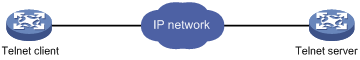
By default, Telnet service is enabled.
· The IP address is 192.168.0.50.
· The login username is admin.
· The login password is h3capadmin.
· The user privilege level is 3.
Table 5 shows the Telnet server and client configuration requirements.
Table 5 Telnet server and Telnet client configuration requirements
|
Device role |
Requirements |
|
Telnet server |
Enable Telnet server. Configure the IP address of a Layer 3 interface, and make sure the Telnet server and client can reach each other. Configure the authentication mode and other settings. |
|
Telnet client |
Run the Telnet client program. Obtain the IP address of the Layer 3 interface on the server. |
To control Telnet access to the device operating as a Telnet server, configure login authentication and user privilege levels for Telnet users.
The following are authentication modes available for controlling Telnet logins:
· None—Requires no authentication. This mode is insecure.
· Password—Requires a password for accessing the CLI. If your password was lost, log in to the device through the console port to re-set the password.
· Scheme—Uses the AAA module to provide local or remote authentication. You must provide a username and password to access the CLI. If the password configured in the local user database was lost, log in to the device through the console port and re-set the password. If the username or password configured on a remote server was lost, contact the server administrator for help.
Table 6 Configuration required for different Telnet login authentication modes
|
Authentication mode |
Configuration tasks |
Reference |
|
None |
Set the authentication mode to none for the VTY user interface. |
|
|
Password |
Enable password authentication on the VTY user interface. Set a password. |
|
|
Scheme |
Enable scheme authentication on the VTY user interface. Configure local or remote authentication settings. To configure local authentication: 1. Configure a local user and specify the password. 2. Configure the device to use local authentication. To configure remote authentication: 1. Configure the RADIUS or HWTACACS scheme on the device. 2. Configure the username and password on the AAA server. 3. Configure the device to use the scheme for user authentication. |
Configuring none authentication for Telnet login
|
Step |
Command |
Remarks |
|
1. Enter system view. |
system-view |
N/A |
|
2. Enable Telnet server. |
telnet server enable |
By default, the Telnet server function is enabled. |
|
3. Enter one or multiple VTY user interface views. |
user-interface vty first-number [ last-number ] |
N/A |
|
4. Enable none authentication mode. |
authentication-mode none |
By default, password authentication is enabled for VTY user interfaces. |
|
5. Configure the command level for login users on the current user interfaces. |
user privilege level level |
By default, the default command level is 0 for VTY user interfaces. |
|
6. Configure common settings for the VTY user interfaces. |
See "Configuring common VTY user interface settings (optional)." |
Optional. |
The next time you attempt to Telnet to the device, you do not need to provide any username or password. If the maximum number of login users has been reached, your login attempt fails and the message "All user interfaces are used, please try later!" appears.
Configuring password authentication for Telnet login
|
Step |
Command |
Remarks |
|
1. Enter system view. |
system-view |
N/A |
|
2. Enable Telnet server. |
telnet server enable |
By default, the Telnet server function is enabled. |
|
3. Enter one or multiple VTY user interface views. |
user-interface vty first-number [ last-number ] |
N/A |
|
4. Enable password authentication. |
authentication-mode password |
By default, password authentication is enabled for VTY user interfaces. |
|
5. Set a password. |
set authentication password { cipher | simple } password |
By default, no password is set. |
|
6. Configure the user privilege level for login users. |
user privilege level level |
The default level is 0. |
|
7. Configure common settings for VTY user interfaces. |
See "Configuring common VTY user interface settings (optional)." |
Optional. |
The next time you attempt to Telnet to the device, you must provide the configured login password. If the maximum number of login users has been reached, your login attempt fails and the message "All user interfaces are used, please try later!" appears.
Configuring scheme authentication for Telnet login
When scheme authentication is used, you can choose to configure the command authorization and command accounting functions.
If command authorization is enabled, a command is available only if the user has the commensurate user privilege level and is authorized to use the command by the AAA scheme.
Command accounting allows the HWTACACS server to record all commands executed by users, regardless of command execution results. This function helps control and monitor user behaviors on the device. If command accounting is enabled and command authorization is not enabled, every executed command is recorded on the HWTACACS server. If both command accounting and command authorization are enabled, only the authorized and executed commands are recorded on the HWTACACS server.
Follow these guidelines when you configure scheme authentication for Telnet login:
· To make the command authorization or command accounting function take effect, apply an HWTACACS scheme to the intended ISP domain. This scheme must specify the IP address of the authorization server and other authorization parameters.
· If the local authentication scheme is used, use the authorization-attribute level level command in local user view to set the user privilege level on the device.
· If a RADIUS or HWTACACS authentication scheme is used, set the user privilege level on the RADIUS or HWTACACS server.
To configure scheme authentication for Telnet login:
|
Step |
Command |
Remarks |
|
1. Enter system view. |
system-view |
N/A |
|
2. Enable Telnet server. |
telnet server enable |
By default, the Telnet server function is enabled. |
|
3. Enter one or multiple VTY user interface views. |
user-interface vty first-number [ last-number ] |
N/A |
|
4. Enable scheme authentication. |
authentication-mode scheme |
By default, password authentication is enabled for VTY user interfaces. Whether local, RADIUS, or HWTACACS authentication is adopted depends on the configured AAA scheme. By default, local authentication is adopted. |
|
5. Enable command authorization. |
command authorization |
Optional. By default, command authorization is disabled. The commands available for a user only depend on the user privilege level. |
|
6. Enable command accounting. |
command accounting |
Optional. By default, command accounting is disabled. The accounting server does not record the commands executed by users. |
|
7. Exit to system view. |
quit |
N/A |
|
8. Apply an AAA authentication scheme to the intended domain. |
a.
Enter ISP domain view: b.
Apply an AAA scheme to the domain: c.
Exit to system view: |
Optional. By default, local authentication is used. For local authentication, configure local user accounts. For RADIUS or HWTACACS authentication, configure the RADIUS or HWTACACS scheme on the device and configure authentication settings (including the username and password) on the server. For more information about AAA configuration, see Security Configuration Guide. |
|
9. Create a local user and enter local user view. |
local-user user-name |
N/A |
|
10. Set a password. |
password { cipher | simple } password |
N/A |
|
11. Specify the command level of the local user. |
authorization-attribute level level |
Optional. |
|
12. Specify Telnet service for the local user. |
service-type telnet |
N/A |
|
13. Exit to system view. |
quit |
N/A |
|
14. Configure common settings for VTY user interfaces. |
See "Configuring common VTY user interface settings (optional)." |
Optional. |
The next time you attempt to Telnet to the CLI, you must provide the configured login username and password. If you are required to pass a second authentication, you must also provide the correct password to access the CLI. If the maximum number of login users has been reached, your login attempt fails and the message "All user interfaces are used, please try later!" appears.
Configuring common VTY user interface settings (optional)
You might be unable to access the CLI through a VTY user interface after configuring the auto-execute command command on it. Before you configure the command and save the configuration, make sure you can access the CLI through a different user interface.
To configure common settings for VTY user interfaces:
|
Step |
Command |
Remarks |
|
1. Enter system view. |
system-view |
N/A |
|
2. Enter one or multiple VTY user interface views. |
user-interface vty first-number [ last-number ] |
N/A |
|
3. Enable the terminal service. |
shell |
Optional. By default, terminal service is enabled. |
|
4. Enable the user interfaces to support Telnet, SSH, or both of them. |
protocol inbound { all | ssh | telnet } |
Optional. By default, both Telnet and SSH are supported. The configuration takes effect the next time you log in. |
|
5. Define a shortcut key for terminating tasks. |
escape-key { default | character } |
Optional. By default, pressing Ctrl+C terminates a task. |
|
6. Configure the type of terminal display. |
terminal type { ansi | vt100 } |
Optional. By default, the terminal display type is ANSI. |
|
7. Set the maximum number of lines to be displayed on a screen. |
screen-length screen-length |
Optional. By default, up to 24 lines is displayed on a screen. A value of 0 disables the function. |
|
8. Set the size of command history buffer. |
history-command max-size value |
Optional. By default, the buffer saves 10 history commands. |
|
9. Set the idle-timeout timer. |
idle-timeout minutes [ seconds ] |
Optional. The default idle-timeout is 10 minutes for all user interfaces. The system automatically terminates the user's connection if there is no information interaction between the device and the user within the timeout time. Setting idle-timeout to 0 disables the timer. |
|
10. Specify a command to be automatically executed when a user logs in to the user interfaces. |
auto-execute command command |
Optional. By default, no automatically executed command is specified. The command auto-execute function is typically used for redirecting a Telnet user to a specific host. After executing the specified command and performing the incurred task, the system automatically disconnect the Telnet session. |
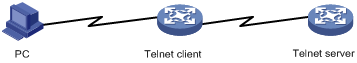
Using the device to log in to a Telnet server
You can use the device as a Telnet client to log in to a Telnet server. If the server is located in a different subnet than the device, make sure the two devices have routes to reach each other.
Figure 6 Telnetting from the device to a Telnet server
To use the device to log in to a Telnet server:
|
Step |
Command |
Remarks |
|
1. Enter system view. |
system-view |
N/A |
|
2. Specify the source IPv4 address or source interface for outgoing Telnet packets. |
telnet client source { interface interface-type interface-number | ip ip-address } |
Optional. By default, no source IPv4 address or source interface is specified. The device automatically selects a source IPv4 address. |
|
3. Exit to user view. |
quit |
N/A |
|
4. Use the device to log in to a Telnet server. |
·
Log in to an IPv4 Telnet server: ·
Log in to an IPv6 Telnet server: |
Use either command. |
Logging in through SSH
SSH offers a secure approach to remote login. By providing encryption and strong authentication, it protects devices against attacks such as IP spoofing and plain text password interception. You can use an SSH client to log in to the device operating as an SSH server for remote management, as shown in Figure 7. You can also use the device as an SSH client to log in to an SSH server.
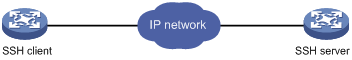
Table 7 shows the SSH server and client configuration required for a successful SSH login.
Table 7 SSH server and client requirements
|
Device role |
Requirements |
|
SSH server |
Assign an IP address to a Layer 3 interface, and make sure the interface and the client can reach each other. Configure the authentication mode and other settings. |
|
SSH client |
If a host operates as an SSH client, run the SSH client program on the host. Obtain the IP address of the Layer 3 interface on the server. |
To control SSH access to the device operating as an SSH server, configure authentication and user privilege level for SSH users. By default, password authentication is adopted for SSH login, but no login password is configured. To allow SSH access to the device after you enable the SSH server, you must configure a password.
Configuring the SSH server on the device
When scheme authentication is used, you can choose to configure the command authorization and command accounting functions.
If command authorization is enabled, a command is available only if the user has the commensurate user privilege level and is authorized to use the command by the AAA scheme.
Command accounting allows the HWTACACS server to record all commands executed by users, regardless of command execution results. This function helps control and monitor user behaviors on the device. If command accounting is enabled and command authorization is not enabled, every executed command is recorded on the HWTACACS server. If both command accounting and command authorization are enabled, only the authorized and executed commands are recorded on the HWTACACS server.
Follow these guidelines when you configure the SSH server:
· To make the command authorization or command accounting function take effect, apply an HWTACACS scheme to the intended ISP domain. This scheme must specify the IP address of the authorization server and other authorization parameters.
· If the local authentication scheme is used, use the authorization-attribute level level command in local user view to set the user privilege level on the device.
· If a RADIUS or HWTACACS authentication scheme is used, set the user privilege level on the RADIUS or HWTACACS server.
The SSH client authentication method is password in this configuration procedure. For more information about SSH and publickey authentication, see Security Configuration Guide.
To configure the SSH server on the device:
|
Step |
Command |
Remarks |
|
1. Enter system view. |
system-view |
N/A |
|
2. Create local key pairs. |
public-key local create { ecdsa | rsa } |
By default, no local key pairs are created. |
|
3. Enable SSH server. |
ssh server enable |
By default, SSH server is disabled. |
|
4. Enter one or multiple VTY user interface views. |
user-interface vty first-number [ last-number ] |
N/A |
|
5. Enable scheme authentication. |
authentication-mode scheme |
By default, password authentication is enabled on VTY user interfaces. |
|
6. Enable the user interfaces to support Telnet, SSH, or both of them. |
protocol inbound { all | ssh } |
Optional. By default, both Telnet and SSH are supported. |
|
7. Enable command authorization. |
command authorization |
Optional. By default, command authorization is disabled. The commands available for a user only depend on the user privilege level. |
|
8. Enable command accounting. |
command accounting |
Optional. By default, command accounting is disabled. The accounting server does not record the commands executed by users. |
|
9. Exit to system view. |
quit |
N/A |
|
10. Apply an AAA authentication scheme to the intended domain. |
a.
Enter the ISP domain view: b.
Apply the specified AAA scheme to the domain: c.
Exit to system view: |
Optional. For local authentication, configure local user accounts. For RADIUS or HWTACACS authentication, configure the RADIUS or HWTACACS scheme on the device and configure authentication settings (including the username and password) on the server. For more information about AAA configuration, see Security Configuration Guide. |
|
11. Create a local user and enter local user view. |
local-user user-name |
N/A |
|
12. Set a password for the local user. |
password { cipher | simple } password |
N/A |
|
13. Specify the command level of the user. |
authorization-attribute level level |
Optional. |
|
14. Specify SSH service for the user. |
service-type ssh |
N/A |
|
15. Exit to system view. |
quit |
N/A |
|
16. Create an SSH user, and specify the authentication mode for the SSH user. |
ssh user username service-type stelnet authentication-type { password | { any | password-publickey | publickey } assign publickey keyname } |
N/A |
|
17. Configure common settings for VTY user interfaces. |
See "Configuring common VTY user interface settings (optional)." |
Optional. |
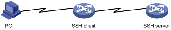
Using the device to log in to an SSH server
You can use the device as an SSH client to log in to an SSH server. If the server is located in a different subnet than the device, make sure the two devices have routes to reach each other.
Figure 8 Logging in to an SSH server from the device
Perform the following tasks in user view:
|
Task |
Command |
Remarks |
|
Log in to an IPv4 SSH server. |
ssh2 server |
The server argument represents the IPv4 address or host name of the server. |
|
Log in to an IPv6 SSH server. |
ssh2 ipv6 server |
The server argument represents the IPv6 address or host name of the server. |
To work with the SSH server, you might need to configure the SSH client. For information about configuring the SSH client, see Security Configuration Guide.
Displaying and maintaining CLI login
|
Task |
Command |
Remarks |
|
Display information about the user interfaces that are being used. |
display users [ | { begin | exclude | include } regular-expression ] |
Available in any view. |
|
Display information about all user interfaces the device supports. |
display users all [ | { begin | exclude | include } regular-expression ] |
Available in any view. |
|
Display user interface information. |
display user-interface [ num1 | { console | vty } num2 ] [ summary ] [ | { begin | exclude | include } regular-expression ] |
Available in any view. |
|
Display the configuration of the device when it serves as a Telnet client. |
display telnet client configuration [ | { begin | exclude | include } regular-expression ] |
Available in any view. |
|
Release a user interface. |
free user-interface { num1 | { console | vty } num2 } |
Available in user view. Multiple users can log in to the device to simultaneously configure the device. When necessary, you can execute this command to release some connections. You cannot use this command to release the connection you are using. |
|
Lock the current user interface. |
lock |
Available in user view. By default, the system does not automatically lock a user interface. |
|
Send messages to user interfaces. |
send { all | num1 | { console | vty } num2 } |
Available in user view. |
The device provides a built-in Web server for you to configure the device through a Web browser.
Web login is enabled by default.
· The IP address is 192.168.0.50.
· The login username is admin.
· The login password is h3capadmin.
· The user privilege level is 3.
The device supports using HTTP 1.0 and HTTPS for webpage data transfer across the Internet.
HTTPS uses SSL to ensure the integrity and security of data exchanged between the client and the server, and it is more secure than HTTP. You can define a certificate attribute-based access control policy to allow only legal clients to access the Web interface.
HTTP login and HTTPS login are separate login methods. To use HTTPS login, you do not need to configure HTTP login.
Table 8 shows the basic Web login configuration requirements.
Table 8 Basic Web login configuration requirements
|
Object |
Requirements |
|
Device |
Assign an IP address to a Layer 3 interface. Configure routes to make sure the interface and the PC can reach each other.
Perform either or both of the following tasks: |
|
PC |
Install a Web browser. Obtain the IP address of the device's Layer 3 interface. |
Configuring HTTP login
|
Step |
Command |
Remarks |
|
1. Specify a fixed verification code for Web login. |
web captcha verification-code |
Optional. By default, no fixed verification code is configured for Web login, and a Web user must enter the verification code provided on the login page at login. This command is available in user view. |
|
2. Enter system view. |
system-view |
N/A |
|
3. Enable the HTTP service. |
ip http enable |
By default, the HTTP service is enabled. |
|
4. Configure the HTTP service port number. |
ip http port port-number |
Optional. The default HTTP service port number is 80. If you execute the command multiple times, the last one takes effect. |
|
5. Associate the HTTP service with an ACL. |
ip http acl acl-number |
Optional. By default, the HTTP service is not associated with any ACL. Associating the HTTP service with an ACL enables the device to allow only clients permitted by the ACL to log in. |
|
6. Set the Web connection timeout time. |
web idle-timeout minutes |
Optional. |
|
7. Set the size of the buffer for Web login logging. |
web logbuffer size pieces |
Optional. |
|
8. Create a local user and enter local user view. |
local-user user-name |
N/A |
|
9. Configure a password for the local user. |
password { cipher | simple } password |
N/A |
|
10. Specify the command level of the local user. |
authorization-attribute level level |
N/A |
|
11. Authorize the user to use the Web service. |
service-type web |
N/A |
|
12. Exit to system view. |
quit |
N/A |
|
13. Create a VLAN interface and enter its view. |
interface vlan-interface vlan-interface-id |
If the VLAN interface already exists, the command enters its view. You could replace this VLAN interface with any other Layer 3 interface as appropriate. |
|
14. Assign an IP address and subnet mask to the interface. |
ip address ip-address { mask | mask-length } |
N/A |
Configuring HTTPS login
The device supports the following HTTPS login modes:
· Simplified mode—To make the device operate in this mode, you only need to enable HTTPS service on the device. The device will use a self-signed certificate (a certificate that is generated and signed by the device itself, rather than a CA) and the default SSL settings. This mode is simple to configure but has potential security risks.
· Secure mode—To make the device operate in this mode, you must enable HTTPS service on the device, specify an SSL server policy for the service, and configure PKI domain-related parameters. This mode is more complicated to configure but provides higher security.
For more information about SSL and PKI, see Security Configuration Guide.
Follow these guidelines when you configure HTTPS login:
· If the HTTPS service and the SSL VPN service use the same port number, they must have the same SSL server policy. Otherwise, only one of the two services can be enabled.
· If the HTTPS service and the SSL VPN service use the same port number and the same SSL server policy, disable the two services before you modify the SSL server policy, and re-enable them after the modification. Otherwise, the SSL server policy does not take effect.
To configure HTTPS login:
|
Step |
Command |
Remarks |
|
1. Specify a fixed verification code for Web login. |
web captcha verification-code |
Optional. By default, no fixed verification code is configured for Web login, and a Web user must enter the verification code provided on the login page at login. This command is available in user view. |
|
2. Enter system view. |
system-view |
N/A |
|
3. Associate the HTTPS service with an SSL server policy. |
ip https ssl-server-policy policy-name |
Optional. By default, the HTTPS service is not associated with any SSL server policy, and the device uses a self-signed certificate for authentication. Disabling the HTTPS service de-associates the SSL service policy from the HTTPS service. To re-enable the HTTPS service, you must reconfigure this command again. If the HTTPS service has been enabled, any changes to the SSL server policy associated with it do not take effect. |
|
4. Enable the HTTPS service. |
ip https enable |
By default, HTTPS is disabled. Enabling the HTTPS service triggers an SSL handshake negotiation process: · If a local certificate exists on the device, the SSL negotiation succeeds and the HTTPS service starts up. · If no local certificate exists, a certificate application process is triggered by the SSL handshake negotiation. Because the application process takes a long time, the SSL negotiation often fails and the HTTPS service cannot be started. In that case, execute this command multiple times to start the HTTPS service. |
|
5. Associate the HTTPS service with a certificate attribute-based access control policy. |
ip https certificate access-control-policy policy-name |
Optional. By default, the HTTPS service is not associated with any certificate-based attribute access control policy. The device uses the associated policy to control client access rights. You must configure the client-verify enable command and at least one permit rule in the associated SSL server policy. Otherwise, no clients can log in through HTTPS. For more information about certificate attribute-based access control policies, see the chapter on PKI in Security Configuration Guide. |
|
6. Specify the HTTPS service port number. |
ip https port port-number |
Optional. The default HTTPS service port number is 443. |
|
7. Associate the HTTPS service with an ACL. |
ip https acl acl-number |
By default, the HTTPS service is not associated with any ACL. The device allows only clients permitted by the associated ACL to log in. |
|
8. Set the HTTPS user authentication mode. |
web https-authorization mode { auto | manual } |
Optional. The default HTTPS user authentication mode is manual. In manual mode, a user must enter the correct username and password to log in through HTTPS. In auto mode, the device first authenticates users by their certificates: · If the certificate is correct and not expired, the CN field in the certificate is used as the username to perform AAA authentication. If the authentication succeeds, the Web interface of the device appears on the user's terminal. · If the certificate is correct and not expired, but the AAA authentication fails, the device shows the Web login page and the user must enter the correct username and password to log in. · If the certificate is incorrect or expired, the HTTPS connection is terminated. |
|
9. Set the Web user connection timeout time. |
web idle-timeout minutes |
Optional. |
|
10. Set the size of the buffer for Web login logging. |
web logbuffer size pieces |
Optional. |
|
11. Create a local user and enter local user view. |
local-user user-name |
N/A |
|
12. Configure a password for the local user. |
password { cipher | simple } password |
N/A |
|
13. Specify the command level of the local user. |
authorization-attribute level level |
N/A |
|
14. Authorize the local user to use the Web service. |
service-type web |
N/A |
|
15. Exit to system view. |
quit |
N/A |
|
16. Create a VLAN interface and enter its view. |
interface vlan-interface vlan-interface-id |
If the VLAN interface already exists, the command enters its view. You could replace this VLAN interface with any other Layer 3 interface as appropriate. |
|
17. Assign an IP address and subnet mask to the interface. |
ip address ip-address { mask | mask-length } |
N/A |
Displaying and maintaining Web login
|
Task |
Command |
Remarks |
|
Display information about Web users. |
display web users [ | { begin | exclude | include } regular-expression ] |
Available in any view. |
|
Display HTTP state information. |
display ip http [ | { begin | exclude | include } regular-expression ] |
Available in any view. |
|
Display HTTPS state information. |
display ip https [ | { begin | exclude | include } regular-expression ] |
Available in any view. |
HTTP login configuration example
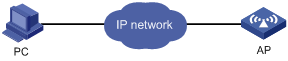
Network requirements
As shown in Figure 9, configure the AP to allow the PC to log in over the IP network by using HTTP.
Configuration procedure
1. Configure the AP:
# Create VLAN-interface 1.
<Sysname> system-view
[Sysname] interface vlan-interface 1
# Assign the IP address 192.168.0.58/24 to the interface.
[Sysname-VLAN-interface1] ip address 192.168.0.58 255.255.255.0
[Sysname-VLAN-interface1] quit
# Create a local user named admin, and set the password to admin for the user. Specify the Web service type for the local user, and set the command level to 3 for this user.
[Sysname] local-user admin
[Sysname-luser-admin] service-type web
[Sysname-luser-admin] authorization-attribute level 3
[Sysname-luser-admin] password simple admin
2. Verify the configuration:
# On the PC, run the Web browser. Enter the IP address of the AP in the address bar. The Web login page appears, as shown in Figure 10.
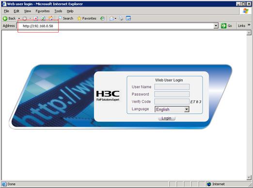
# Enter the user name, password, verify code, select English, and click Login. The homepage appears. After login, you can configure the AP through the Web interface.
HTTPS login configuration example
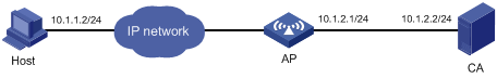
Network requirements
As shown in Figure 11, to allow only authorized users to access the AP's Web interface, configure the AP as the HTTPS server and the host as the HTTPS client. Request a certificate for each of them.
Configuration procedure
In this example, the CA uses the name new-ca, runs Windows Server, and is installed with the SCEP add-on. The AP, host, and CA can reach one another.
1. Configure the AP (HTTPS server):
# Configure a PKI entity, and set the common name to http-server1 and the FQDN to ssl.security.com.
<AP> system-view
[AP] pki entity en
[AP-pki-entity-en] common-name http-server1
[AP-pki-entity-en] fqdn ssl.security.com
[AP-pki-entity-en] quit
# Create a PKI domain, specify the trusted CA as new-ca, the URL of the server for certificate request as http://10.1.2.2/certsrv/mscep/mscep.dll, authority for certificate request as RA, and the entity for certificate request as en.
[AP] pki domain 1
[AP-pki-domain-1] ca identifier new-ca
[AP-pki-domain-1] certificate request url http://10.1.2.2/certsrv/mscep/mscep.dll
[AP-pki-domain-1] certificate request from ra
[AP-pki-domain-1] certificate request entity en
[AP-pki-domain-1] quit
# Create RSA local key pairs.
[AP] public-key local create rsa
The range of public key size is (512 ~ 2048).
NOTES: If the key modulus is greater than 512,
It will take a few minutes.
Press CTRL+C to abort.
Input the bits of the modulus[default = 1024]:
Generating Keys...
+++++
++++++++++++++
+++++++++++++
++++++++
# Retrieve the CA certificate.
[AP] pki retrieval-certificate ca domain 1
The trusted CA's finger print is:
MD5 fingerprint:3352 F952 0D8E FDF8 AB98 08ED 11D3 B005
SHA1 fingerprint:1628 60B1 367B D012 D08C 85D3 8D2F 5D10 1F9D 4B39
Is the finger print correct?(Y/N): y
# Request a local certificate for the AP through SCEP.
[AP] pki request-certificate domain 1
# Create SSL server policy myssl, specify PKI domain 1 for the SSL server policy, and enable certificate-based SSL client authentication.
[AP] ssl server-policy myssl
[AP-ssl-server-policy-myssl] pki-domain 1
[AP-ssl-server-policy-myssl] client-verify enable
[AP-ssl-server-policy-myssl] quit
# Create certificate attribute group mygroup1 and configure a certificate attribute rule for it, specifying that the distinguished name in the subject name includes the string of new-ca.
[AP] pki certificate attribute-group mygroup1
[AP-pki-cert-attribute-group-mygroup1] attribute 1 issuer-name dn ctn new-ca
[AP-pki-cert-attribute-group-mygroup1] quit
# Create certificate attribute-based access control policy myacp and configure a certificate attribute-based access control rule, specifying that a certificate is considered valid when it matches an attribute rule in certificate attribute group myacp.
[AP] pki certificate access-control-policy myacp
[AP-pki-cert-acp-myacp] rule 1 permit mygroup1
[AP-pki-cert-acp-myacp] quit
# Associate the HTTPS service with SSL server policy myssl.
[AP] ip https ssl-server-policy myssl
# Associate the HTTPS service with certificate attribute-based access control policy myacp.
[AP] ip https certificate access-control-policy myacp
# Enable the HTTPS service.
[AP] ip https enable
# Create a local user named usera, set the password to 123, and specify the Web service type.
[AP] local-user usera
[AP-luser-usera] password simple 123
[AP-luser-usera] service-type web
2. Configure the host (HTTPS client):
On the host, run the IE browser, and then enter http://10.1.2.2/certsrv in the address bar and request a certificate for the host as prompted.
3. Verify the configuration:
On the host, enter https://10.1.1.1 in the browser's address bar and then select the certificate issued by new-ca. When the Web login page of the AP appears, enter the username usera and password 123 to log in to the Web interface.
For more information about PKI configuration commands, SSL configuration commands, and the public-key local create rsa command, see Security Command Reference.
You can run SNMP on an NMS to access the device MIB and perform GET and SET operations to manage and monitor the device. The device supports SNMPv1, SNMPv2c, and SNMPv3, and can work with various network management software products, including IMC. For more information about SNMP, see Network Management and Monitoring Configuration Guide.
By default, SNMP access is disabled. To enable SNMP access, log in to the device through any other method and configure SNMP login.
Configuring SNMP login
Connect the PC (the NMS) and the device to the network, making sure they can reach each other, as shown in Figure 12. This document describes only the basic SNMP configuration procedures on the device.
|
|
IMPORTANT: To make SNMP operate correctly, make sure the SNMP settings (including the SNMP version) on the NMS are consistent with those on the device. |
Prerequisites
· Assign an IP address to a Layer 3 interface on the device.
· Configure routes to make sure the NMS and the Layer 3 interface can reach each other.
Configuring SNMPv3 settings
|
Step |
Command |
Remarks |
|
1. Enter system view. |
system-view |
N/A |
|
2. Enable the SNMP agent. |
snmp-agent |
Optional. By default, the SNMP agent is disabled. You can enable SNMP agent with this command or any command that begins with snmp-agent. |
|
3. Configure an SNMP group and specify its access right. |
snmp-agent group v3 group-name [ authentication | privacy ] [ read-view read-view ] [ write-view write-view ] [ notify-view notify-view ] [ acl acl-number ] * |
By default, no SNMP group is configured. |
|
4. Add a user to the SNMP group. |
snmp-agent usm-user v3 user-name group-name [ [ cipher ] authentication-mode { md5 | sha } auth-password [ privacy-mode { 3des | aes128 | des56 } priv-password ] ] [ acl acl-number ] * |
N/A |
Configuring SNMPv1 or SNMPv2c settings
|
Step |
Command |
Remarks |
|
1. Enter system view. |
system-view |
N/A |
|
2. Enable the SNMP agent. |
snmp-agent |
Optional. By default, the SNMP agent is disabled. You can enable SNMP agent with this command or any command that begins with snmp-agent. |
|
3. Create or update MIB view information. |
snmp-agent mib-view { excluded | included } view-name oid-tree [ mask mask-value ] |
Optional. By default, the MIB view name is ViewDefault and OID is 1. |
|
4. Configure the SNMP access right. |
·
(Approach 1) Specify the SNMP NMS access right
directly by configuring an SNMP community: · (Approach 2) Configure an SNMP group and add a user to the SNMP group: a. snmp-agent group { v1 | v2c } group-name [ read-view read-view ] [ write-view write-view ] [ notify-view notify-view ] [ acl acl-number ] * b. snmp-agent usm-user { v1 | v2c } user-name group-name [ acl acl-number ] * |
Use either approach. The username in approach 2 is equivalent to the community name used in approach 1, and must be the same as the community name configured on the NMS. |
SNMP login example
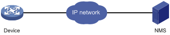
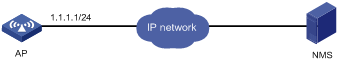
Network requirements
Configure the AP and network management station so you can remotely manage the AP through SNMPv3.
Figure 13 Network diagram
Configuration procedure
1. Configure the AP:
# Assign an IP address to the AP. Make sure the AP and the NMS can reach each other. (Details not shown.)
# Enter system view.
<Sysname> system-view
# Enable the SNMP agent.
[Sysname] snmp-agent
# Configure an SNMP group.
[Sysname] snmp-agent group v3 managev3group read-view test write-view test
# Add a user to the SNMP group.
[Sysname] snmp-agent usm-user v3 managev3user managev3group
2. Configure the NMS:
Make sure the NMS has the same SNMP settings (including the username) as the AP. If not, the AP cannot be discovered or managed by the NMS.
3. Use the network management station to discover, query, and configure the AP. For more information, see the NMS manual.
To harden device security, use ACLs to prevent unauthorized logins. For more information about ACLs, see ACL and QoS Configuration Guide.
Controlling Telnet logins
Use a basic ACL (2000 to 2999) to filter Telnet traffic by source IP address. Use an advanced ACL (3000 to 3999) to filter Telnet traffic by source and/or destination IP address. Use an Ethernet frame header ACL (4000 to 4999) to filter Telnet traffic by source MAC address.
To access the device, a Telnet user must match a permit statement in the ACL applied to the user interface.
Configuring source IP-based Telnet login control
|
Step |
Command |
Remarks |
|
1. Enter system view. |
system-view |
N/A |
|
2. Create a basic ACL and enter its view, or enter the view of an existing basic ACL. |
acl [ ipv6 ] number acl-number [ name name ] [ match-order { config | auto } ] |
By default, no basic ACL exists. |
|
3. Configure an ACL rule. |
·
For IPv4 networks: ·
For IPv6 networks: |
By default, a basic ACL does not contain any rule. |
|
4. Exit the basic ACL view. |
quit |
N/A |
|
5. Enter user interface view. |
user-interface [ type ] first-number [ last-number ] |
N/A |
|
6. Use the ACL to control user logins by source IP address. |
acl [ ipv6 ] acl-number { inbound | outbound } |
· inbound: Filters incoming packets. · outbound: Filters outgoing packets. |
Configuring source/destination IP-based Telnet login control
|
Step |
Command |
Remarks |
|
1. Enter system view. |
system-view |
N/A |
|
2. Create an advanced ACL and enter its view, or enter the view of an existing advanced ACL. |
acl [ ipv6 ] number acl-number [ name name ] [ match-order { config | auto } ] |
By default, no advanced ACL exists. |
|
3. Configure an ACL rule. |
rule [ rule-id ] { permit | deny } rule-string |
N/A |
|
4. Exit advanced ACL view. |
quit |
N/A |
|
5. Enter user interface view. |
user-interface [ type ] first-number [ last-number ] |
N/A |
|
6. Apply the ACL to the user interfaces. |
acl [ ipv6 ] acl-number { inbound | outbound } |
· inbound: Filters incoming Telnet packets. · outbound: Filters outgoing Telnet packets. |
Configuring source MAC-based Telnet login control
Ethernet frame header ACLs apply to Telnet traffic only if the Telnet client and server are located in the same subnet.
To configure source MAC-based Telnet login control:
|
Step |
Command |
Remarks |
|
1. Enter system view. |
system-view |
N/A |
|
2. Create an Ethernet frame header ACL and enter its view. |
acl number acl-number [ name name ] [ match-order { config | auto } ] |
By default, no Ethernet frame header ACL exists. |
|
3. Configure an ACL rule. |
rule [ rule-id ] { permit | deny } rule-string |
N/A |
|
4. Exit Ethernet frame header ACL view. |
quit |
N/A |
|
5. Enter user interface view. |
user-interface [ type ] first-number [ last-number ] |
N/A |
|
6. Use the ACL to control user logins by source MAC address. |
acl acl-number inbound |
inbound: Filters incoming packets. |
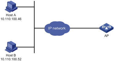
Telnet login control configuration example
Network requirements
Configure the AP in Figure 14 to permit only incoming Telnet packets sourced from Host A and Host B.
Configuration procedure
# Configure basic ACL 2000, and configure rule 1 to permit packets sourced from Host B, and rule 2 to permit packets sourced from Host A.
<Sysname> system-view
[Sysname] acl number 2000 match-order config
[Sysname-acl-basic-2000] rule 1 permit source 10.110.100.52 0
[Sysname-acl-basic-2000] rule 2 permit source 10.110.100.46 0
[Sysname-acl-basic-2000] quit
# Reference ACL 2000 on the user interfaces VTY 0 through VTY 4 so only Host A and Host B can Telnet to the AP.
[Sysname] user-interface vty 0 4
[Sysname-ui-vty0-4] acl 2000 inbound
Configuring source IP-based SNMP login control
Use a basic ACL (2000 to 2999) to control SNMP logins by source IP address. To access the requested MIB view, an NMS must use a source IP address permitted by the ACL.
Configuration procedure
To configure source IP-based SNMP login control:
|
Step |
Command |
Remarks |
|
1. Enter system view. |
system-view |
N/A |
|
2. Create a basic ACL and enter its view, or enter the view of an existing basic ACL. |
acl [ ipv6 ] number acl-number [ name name ] [ match-order { config | auto } ] |
By default, no basic ACL exists. |
|
3. Configure an ACL rule. |
rule [ rule-id ] { deny | permit } [ counting | fragment | logging | source { sour-addr sour-wildcard | any } | time-range time-range-name ] |
N/A |
|
4. Exit the basic ACL view. |
quit |
N/A |
|
5. Apply the ACL to an SNMP community, group, or user. |
·
SNMPv1/v2c community: ·
SNMPv1/v2c group: ·
SNMPv3 group: ·
SNMPv1/v2c user: ·
SNMPv3 user: |
For more information about SNMP, see Network Management and Monitoring Configuration Guide. |
SNMP login control configuration example
Network requirements
Configure the AP in Figure 15 to allow Host A and Host B to access the AP through SNMP.
Configuration procedure
# Create ACL 2000, and configure rule 1 to permit packets sourced from Host B, and rule 2 to permit packets sourced from Host A.
<Sysname> system-view
[Sysname] acl number 2000 match-order config
[Sysname-acl-basic-2000] rule 1 permit source 10.110.100.52 0
[Sysname-acl-basic-2000] rule 2 permit source 10.110.100.46 0
[Sysname-acl-basic-2000] quit
# Associate the ACL with the SNMP community and the SNMP group.
[Sysname] snmp-agent community read aaa acl 2000
[Sysname] snmp-agent group v2c groupa acl 2000
[Sysname] snmp-agent usm-user v2c usera groupa acl 2000
Configuring Web login control
Use a basic ACL (2000 to 2999) to filter HTTP/HTTPS traffic by source IP address, so only Web users whose IP addresses are permitted by the ACL can access the device.
You can also log off suspicious Web users who have been logged in.
Configuring source IP-based Web login control
|
Step |
Command |
Remarks |
|
1. Enter system view. |
system-view |
N/A |
|
2. Create a basic ACL and enter its view, or enter the view of an existing basic ACL. |
acl [ ipv6 ] number acl-number [ name name ] [ match-order { config | auto } ] |
By default, no basic ACL exists. |
|
3. Create rules for this ACL. |
rule [ rule-id ] { deny | permit } [ counting | fragment | logging | source { sour-addr sour-wildcard | any } | time-range time-range-name ] |
N/A |
|
4. Exit the basic ACL view. |
quit |
N/A |
|
5. Associate the HTTP service with the ACL. |
ip http acl acl-number |
Configure either or both of the commands. HTTP login and HTTPS login are separate login methods. To use HTTPS login, you do not need to configure HTTP login. |
|
6. Associate the HTTPS service with the ACL. |
ip https acl acl-number |
Logging off online Web users
|
Task |
Command |
Remarks |
|
Log off online Web users. |
free web-users { all | user-id user-id | user-name user-name } |
Available in user interface view. |
Web login control configuration example
Network requirements
Configure the AP in Figure 16 to provide Web access service only to Host B.
Configuration procedure
# Create ACL 2000, and configure rule 1 to permit packets sourced from Host B.
<Sysname> system-view
[Sysname] acl number 2030 match-order config
[Sysname-acl-basic-2030] rule 1 permit source 10.110.100.52 0
# Associate the ACL with the HTTP service so only the Web users on Host B can access the device.
[Sysname] ip http acl 2030