- Table of Contents
- Related Documents
-
| Title | Size | Download |
|---|---|---|
| 01-Text | 1.42 MB |
Contents
Temperature and humidity requirements· 2
Accessories provided with the AP· 2
Installation tools and equipment 3
Determining the installation position· 4
Installing the AP on a ceiling· 7
Connecting the AP to a power supply· 10
Connecting a PoE power supply· 10
Connecting the local power supply· 10
Connecting the AP to the network· 11
Verifying network connection for the fit AP· 11
Product overview
An H3C WA5620i-ACN AP can act as a fit AP to cooperate with access controller modules or access controllers to provide wireless access for WLAN users. The network settings are configured on the access controller modules or access controllers.
Figure 1 Deployment of WA5620i-ACN APs
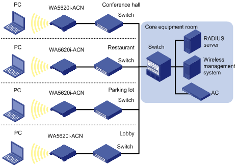
Table 1 H3C WA5620i-ACN specifications
Item | Specification |
Protocol | · IEEE 802.11a/b/g/n/ac · Dual-radio |
Built-in antennas | · 2.4 G antenna: gain 4 dBi · 5 G antenna: gain 4 dBi |
Power consumption | 12.5 to 25 W |
Dimensions (H × W × D) | 52 × 220 × 227 mm (2.05 × 8.66 × 8.94 in) |
Weight | 1.06 kg (2.34 lb) |
Preparing for installation
Safety recommendations
| WARNING! Only qualified personnel can install and remove the AP and its accessories. You must read all safety instructions supplied with the AP before installation and operation. |
To avoid possible bodily injury and equipment damage, read the following safety recommendations before installing the AP. Note that the recommendations do not cover every possible hazardous condition.
· Take adequate safety measures to avoid injury and AP damage.
· Place the AP in a dry and flat location and take anti-slip measures.
· Keep the AP clean and dust-free.
· Do not place the AP in a moist area and avoid liquid surrounding the AP.
· Keep the AP and installation tools away from walkways.
Temperature and humidity requirements
Item | Specification |
Operating temperature (indoor) | –10°C to +55°C (14°F to 131°F) |
Storage temperature | –40°C to +70°C (–40°F to +158°F) |
Operating humidity (noncondensing) | 5% to 95% |
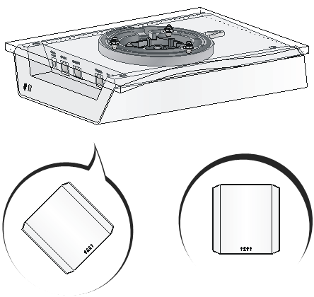
Accessories provided with the AP
Mounting kit |
|
Three sets of M4 × 30 pan head screw, washer, and nut |
|
Three sets of wall anchor kit |
|
MAC address label |
|
One M4 × 10 pan head screw |
|

Installation tools and equipment
When installing the AP, you may need the following tools. Prepare these tools and equipment yourself.
|
|
|
|
Needle-nose pliers | Wire-stripping pliers | Diagonal pliers | Marker |
|
|
|
|
Percussion drill with matching drills | Rubber hammer | Phillips screwdriver |
|

Installing the AP
Figure 2 Installation flowchart

Check before installation
Before installing an AP, perform the following tasks:
· Connect the AP to the power supply and the network. Examine the LEDs to verify that the AP can operate correctly. For more information about AP LEDs, see "Appendix LEDs and ports."
· Verify that cabling on the installation site has been completed.
· To power the AP through PoE/PoE+, use 802.3at PoE+ as a best practice. If 802.3af PoE is used, the AP supports only one spatial stream and the USB and unused Ethernet ports are shutdown automatically.
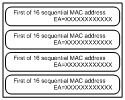
· Record the AP MAC address and serial number marked on the rear of the AP for future use.
| NOTE: · Use a category 5e cable to connect the AP's 2.5 GE port. For the interface to operate at 2500 Mbps, use an H3C switch that provides a 2.5 GE interface. · Use a category 5 cable to connect the AP's GE port. The auto-negotiated transmission rate is 1000 or 100 Mbps. |
Determining the installation position
You can mount the AP to a wall or ceiling. Determine the installation position by observing the following principles:
· Few obstacles such as wall and ceiling exist between AP and clients.
· The AP is far away from electronic devices (such as microwave oven) that may generate radio frequency (RF) noise.
· The AP does not hinder people’s daily work and life.
· The place is not water seeping, water soaking, and condensing.
· A lightning arrester (user supplied) is installed on the AP for cabling outdoors.
· The AP must be over 5-meter away from 3G and 4G stations and antennas.
Installing the AP
Mounting the AP on a wall
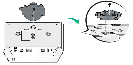
1. Align the screw hole in the AP bracket with the screw hole in the AP rear. Use the M4 × 10 screw to secure the AP bracket to the AP.
Figure 3 Attaching the AP bracket to the AP rear

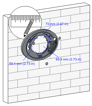
2. Mark the installation holes on the wall by using the mounting bracket, as shown in Figure 4.
Figure 4 Mounting holes in the mounting bracket
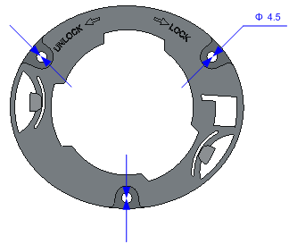
Figure 5 Marking installation holes on the wall
3. Drill holes with a diameter of 5 mm (0.197 in) and a depth of 30 mm (1.18 in) in the marked locations, as shown in Figure 6.
Figure 6 Drilling holes in the wall

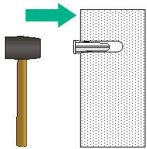
4. Insert a wall anchor into each hole, and tap the wall anchor with a rubber hammer until it is all flush with the wall surface, as shown in Figure 7.
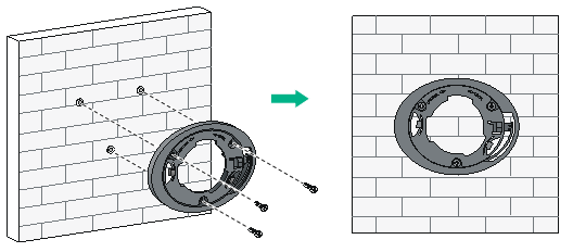
5. Align the mounting holes in the mounting bracket with the anchors and insert screws through the mounting holes into the wall anchors. Adjust the position of the mounting bracket and tighten the screws.
Figure 8 Attaching the mounting bracket to the wall
6. Connect the AP to the LAN by using Ethernet cables.
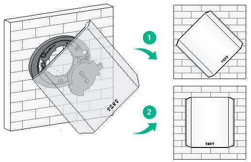
7. Align the AP at a 45 degree angle with the mounting bracket, and rotate the AP clockwise until it clicks into place, as shown in Figure 9.
Figure 9 Attaching the AP to the wall mounting bracket
Installing the AP on a ceiling
| CAUTION: The ceiling for installing the AP must be less than 18 mm (0.71 in) in thickness, and can bear a load of 5 kg (11.02 lb). As a best practice, reinforce the ceiling by using boards if the ceiling is not strong enough. |
To install the AP on a ceiling:
1. Align the screw hole in the AP bracket with the screw hole in the AP rear. Use the M4 × 10 screw to secure the AP bracket to the AP.
Figure 10 Attaching the AP bracket to the AP rear
2. Mark the installation holes on the ceiling by using the mounting bracket.
3. Drill holes with a diameter of 5 mm (0.197 in) in the marked positions, as shown in Figure 11.
Figure 11 Drilling holes in the ceiling

4. Insert the M4 × 30 pan head screws through the mounting holes in the mounting bracket and the holes in the ceiling. Fasten washers and nuts at the other side of the ceiling to attach the mounting bracket to the ceiling, as shown in Figure 12.
Figure 12 Attaching the mounting bracket to the ceiling
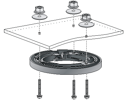
5. Connect the AP to the LAN by using Ethernet cables.
6. Align the AP with the mounting bracket and rotate the AP clockwise until it clicks into place, as shown in Figure 13.
Figure 13 Attaching the AP to the ceiling mounting bracket
7. Verify that the AP is securely installed to prevent it from falling off.
Connecting the AP to a power supply
| CAUTION: Before powering on the AP, make sure the power supply is reliably grounded. |
You can power the AP with a local power or by using PoE+ or PoE.
If 802.3af PoE is used, the AP supports only one spatial stream and the USB and unused Ethernet ports are shutdown automatically.
Connecting a PoE power supply
Use an Ethernet cable to connect the Ethernet interface that supports PoE on the AP to a PoE switch.
Figure 14 Connecting a PoE power supply

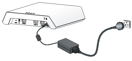
Connecting the local power supply
No AC/DC adapter and power cord are provided with the AP. Prepare them yourself if required.
Table 2 AC/DC adapter specifications
Item | Specification |
Input | 100 VAC to 240 VAC |
Output | +54V |
You can power the AP by using an AC/DC adapter. Use the AC/DC adapter to connect the power port of the AP to the local power source.
Figure 15 Connecting the local power supply
Check after power-on
Verify that the AP is powered on and operating correctly by examining the AP status LED. For more information about AP LEDs, see "Appendix LEDs and ports."
Connecting the AP to the network
Connect an Ethernet port of the AP to an Ethernet port of an Ethernet switch for Internet or MAN access.
Verifying network connection for the fit AP
All settings of the fit AP are configured on the AC. Use the display wlan ap all command on the AC that connects to the fit AP. If the AP status is R/M, the AP is connected to the network.
Total number of APs: 1
Total number of connected APs: 1
Total number of connected manual APs: 1
Total number of connected auto APs: 0
Total number of connected common APs: 0
Total number of connected WTUs: 0
Total number of inside APs: 0
Maximum supported APs: 3072
Remaining APs: 3070
Total AP licenses: 128
Remaining AP licenses: 127
AP information
State : I = Idle, J = Join, JA = JoinAck, IL = ImageLoad
C = Config, DC = DataCheck, R = Run M = Master, B = Backup
AP name APID State Model Serial ID
ap1 1 R WA5620i-ACN 210235A1SVC15C000002
