- Table of Contents
- Related Documents
-
| Title | Size | Download |
|---|---|---|
| 01-Text | 2.05 MB |
Contents
Temperature and humidity requirements 3
Accessories provided with the AP· 3
Installation tools and equipment 4
Determining the installation position· 6
Installing the AP on a ceiling· 9
Connecting the AP to the power supply· 11
Connecting PoE power supply· 11
Connecting local power supply· 12
Connecting the AP to the network· 13
Verifying network connection for the fit AP· 13
Verifying network connection for the fat AP· 13
Logging in through the console port 14
Setting up the configuration environment 14
Connecting the console cable· 14
Setting terminal parameters 15
Logging in through the console port 16
Logging in through Telnet or Web· 17
An H3C WA4320i-ACN AP can act as a fit AP to cooperate with wireless switches or access controllers to provide wireless access for WLAN users. The network settings are configured on the wireless switches or access controllers. The H3C WA4320i-ACN can also act as a fat AP to provide wireless access for WLAN users.
Figure 1 Deployment of the WA4320i-ACN on hotspots (fit AP)
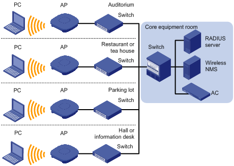
Figure 2 Deployment of the WA4320i-ACN on hotspots (fat AP)
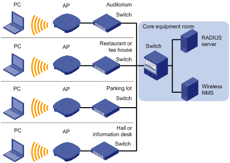
Table 1 H3C WA4320i-ACN specifications
Item | Specification |
Protocol | IEEE 802.11a/b/g/n/ac |
Radio frequency | Dual radio frequency |
Built-in antennas | · 2.4 G antenna: gain 3.1 to 5 dBi · 5 G antenna: gain 5.2 to 6.1 dBi |
Power consumption | 3.95 to 12.95 W |
Dimensions (H × W × D) | 54 × 220 × 220 mm (2.13 × 8.66 × 8.66 in) |
Weight | 0.75 kg (1.65 lb) |
Safety recommendations
| WARNING! Only qualified personnel can install and remove the AP and its accessories. You must read all safety instructions supplied with the AP before installation and operation. |
To avoid possible bodily injury and equipment damage, read the following safety recommendations before installing the AP. Note that the recommendations do not cover every possible hazardous condition.
· Take adequate safety measures to avoid injury and AP damage.
· Place the AP in a dry and flat location and take anti-slip measures.
· Keep the AP clean and dust-free.
· Do not place the AP in a moist area and avoid liquid surrounding the AP.
· Keep the AP and installation tools away from walkways.
Temperature and humidity requirements
Item | Specification |
Operating temperature (indoor) | –10°C to +55°C (14°F to 131°F) |
Storage temperature | –40°C to +70°C (–40°F to +158°F) |
Operating humidity (noncondensing) | 5% to 95% |
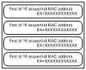
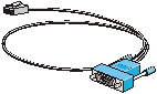
Accessories provided with the AP
Mounting kit (AP bracket, mounting bracket inner part, and mounting bracket outer part, from left to right) |
|
M4 × 30 pan head screw, washer, and nut |
|
Wall anchor kit |
|
MAC address label |
|
Console cable (for fat AP only) |
|
M4 × 10 pan head screw |
|

Installation tools and equipment
When installing the AP, you may need the following tools. Prepare these tools and equipment yourself.
|
|
|
|
Needle-nose pliers | Wire-stripping pliers | Diagonal pliers | Marker |
|
|
|
|
Percussion drill with matching drills | Rubber hammer | Phillips screwdriver |
|

IMPORTANT: The AP is typically installed on a high position. H3C recommends that you log in to and configure the AP before the installation. For more information about logging in to the AP, see “Logging in to the AP.” |
Figure 3 Installation flowchart
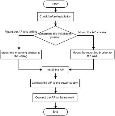
Check before installation
Before installing an AP, perform the following tasks:
· Connect the AP to the power supply and the network. Examine the LEDs to verify that the AP can operate correctly. For more information about AP LEDs, see “Appendix LEDs and ports.”
· Verify that cabling on the installation site has been completed.
· To ensure the PoE performance, H3C recommends that you use GE interfaces for PoE power supply.
· Record the AP MAC address and serial number marked on the rear of the AP for future use.
Determining the installation position
You can mount the AP to a wall or ceiling. Determine the installation position by observing the following principles:
· Few obstacles such as wall and ceiling exist between AP and clients.
· The AP is far away from electronic devices (such as microwave oven) that may generate radio frequency (RF) noise.
· The AP does not hinder people’s daily work and life.
· The place is not water seeping, water soaking, and condensing.
· A lightning arrester (user supplied) is installed on the AP for cabling outdoors.
· The ceiling for installing the AP must be less than 18 mm (0.71 in) in thickness, and can bear a load of 5 kg (11.02 lb). H3C recommends that you reinforce the ceiling by using boards if the ceiling is not strong enough.
· Install the AP more than 5 m (16.40 ft) away from 3G/4G base stations and antennas.
Installing the AP
Mounting the AP on a wall
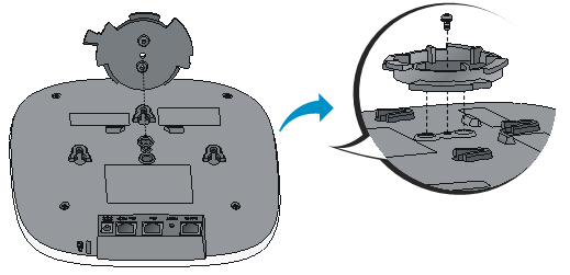
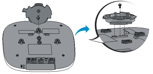
1. Align the screw hole in the AP bracket with the screw hole in the AP rear. Use the M4 × 10 screw to secure the AP bracket to the AP.
Figure 4 Attaching the AP bracket to the AP rear
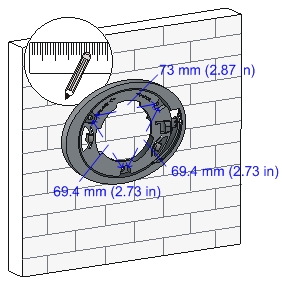
2. Mark the installation holes on the wall by using the mounting bracket, as shown in Figure 5.
Figure 5 Mounting holes in the mounting bracket
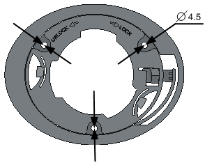
Figure 6 Marking installation holes on the wall
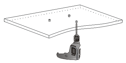
3. Drill holes with a diameter of 5 mm (0.197 in) and a depth of 30 mm (1.18 in) in the marked locations, as shown in Figure 7.
Figure 7 Drilling holes in the wall

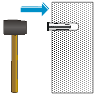
4. Insert a wall anchor into each hole, and tap the wall anchor with a rubber hammer until it is all flush with the wall surface, as shown in Figure 8.
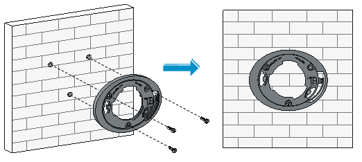
5. Align the mounting holes in the mounting bracket with the anchors and insert screws through the mounting holes into the wall anchors. Adjust the position of the mounting bracket and tighten the screws.
Figure 9 Attaching the mounting bracket to the wall
6. Connect the AP to the LAN by using Ethernet cables.
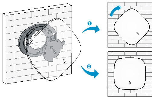
7. Align the AP at a 45 degree angle with the mounting bracket, and rotate the AP clockwise until it clicks into place, as shown in Figure 10.
Figure 10 Attaching the AP to the wall mounting bracket
Installing the AP on a ceiling
1. Align the screw hole in the AP bracket with the screw hole in the AP rear. Use the M4 × 10 screw to secure the AP bracket to the AP.
Figure 11 Attaching the AP bracket to the AP rear
2. Mark the installation holes on the ceiling by using the mounting bracket.
3. Drill holes with a diameter of 5 mm (0.197 in) in the marked positions, as shown in Figure 12.
Figure 12 Drilling holes in the ceiling
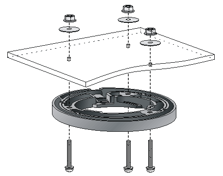
4. Insert the M4 × 30 pan head screws through the mounting holes in the mounting bracket and the holes in the ceiling. Fasten washers and nuts at the other side of the ceiling to attach the mounting bracket to the ceiling, as shown in Figure 13.
Figure 13 Attaching the mounting bracket to the ceiling
5. Connect the AP to the LAN by using Ethernet cables.
6. Align the AP with the mounting bracket and rotate the AP clockwise until it clicks into place, as shown in Figure 14.
Figure 14 Attaching the AP to the ceiling mounting bracket

7. Verify that the AP is securely installed to prevent it from falling off.
Connecting the AP to the power supply
You can power the AP with local power or by using PoE.
Check before power-on
Check the following items before powering on the AP:
· The power supply is reliably grounded when the AP uses local power supply.
· The PoE power supply is reliably grounded when the AP uses PoE power supply.
Connecting PoE power supply
Use an Ethernet cable to connect the Ethernet interface on the AP to an interface on a switch that supports PoE.
Figure 15 Connecting PoE power supply
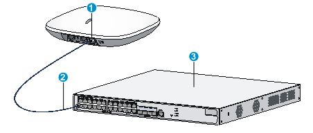
(1) Ethernet interface | (2) Ethernet cable | (3) PoE switch |
Connecting local power supply
| NOTE: The AC/DC adapter and power cord are user-supplied. |
Table 2 AC/DC adapter specifications
Item | Specification |
Input | 100 VAC to 240 VAC |
Output | +48V |
You can power the AP by using an AC/DC adapter. Use the AC/DC adapter to connect the power port of the AP to the local power source.
Figure 16 Connecting local power supply
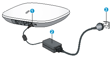
(1) Power port | (2) AC/DC adapter | (3) Power source |
Check after power-on
Verify that the AP is powered on and operating correctly by examining the AP status LED. For more information about AP LEDs, see “Appendix LEDs and ports.”
Connecting the AP to the network
Connect the Ethernet port of the AP to an Ethernet port of an Ethernet switch for Internet or MAN access.
Verifying network connection for the fit AP
All settings of the fit AP are configured on the AC. Use the display wlan ap all command on the AC that connects to the fit AP. If the AP status is R/M, the AP is connected to the network.
Total Number of APs configured : 1
Total Number of configured APs connected : 1
Total Number of auto APs connected : 0
AP Profiles
State : I = Idle, J = Join, JA = JoinAck, IL = ImageLoad
C = Config, R = Run, KU = KeyUpdate, KC = KeyCfm
--------------------------------------------------------------------------------
AP Name State Model Serial-ID
--------------------------------------------------------------------------------
ap1 R/M WA4320i-ACN 210235A1GQB139000435
-------------------------------------------------------------------------------
Verifying network connection for the fat AP
Use the ping command on the fat AP to ping the uplink network device. If the ping operation succeeds, the AP is connected to the network successfully.
| IMPORTANT: The AP is typically installed on a high position. H3C recommends that you log in to and configure the AP before the installation. |
This section applies only when the AP acts as a fat AP. When the AP operates as a fat AP, you can log in to the AP through the console port, or through Telnet or web to configure the AP. Login through the console port is the prerequisite to configuring other login methods. Before you log in to the fat AP through Telnet or Web, obtain the IP address of the AP first.
Logging in through the console port
Prepare the following items before logging in through the console port:
· An 8-core console cable, with a crimped RJ-45 connector at one end, and a DB-9 connector at the other end.
· A configuration terminal with a serial port, such as a laptop or PC.
Setting up the configuration environment
| NOTE: The serial ports on PCs do not support hot swapping. To connect a PC to an operating device, first connect the PC end. To disconnect a PC from an operating device, first disconnect the device end. |
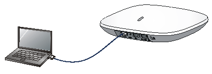
Connecting the console cable
1. Connect the DB-9 connector to the serial port of the PC.
2. Connect the RJ-45 connector to the console port of the AP.
Figure 17 Connecting the console cable
Setting terminal parameters
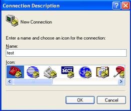
1. Start the PC and run the terminal emulation program such as the HyperTerminal of Windows 95/98/NT/2000/XP.
2. Select Start > All Programs > Accessories > Communications > HyperTerminal, and in the Connection Description dialog box that appears, type the name of the new connection in the Name text box and click OK.
Figure 18 Connection description
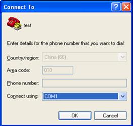
3. Select the serial port to be used from the Connect using drop-down list, and click OK.
Figure 19 Selecting the serial port used by the HyperTerminal connection
4. Set Bits per second to 9600, Data bits to 8, Parity to None, Stop bits to 1, and Flow control to None, and click OK.
Figure 20 Setting the serial port parameters
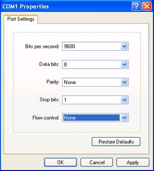
| NOTE: To use the default settings, click Restore Defaults. |
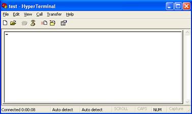
5. Click OK and the system displays the HyperTerminal window.
Figure 21 HyperTerminal window
Logging in through the console port
Power on the AP, and you can see the following information:
System is starting...
Booting Normal Extend BootWare.
……
System application is starting...
Startup configuration file does not exist.
User interface con0 is available.
Press ENTER to get started.
Logging in through Telnet or Web
By default, Telnet login and Web login are enabled. You can log in to the AP by using the following default login information:
· Username—admin.
· Password—h3capadmin.
· IP address of VLAN-interface 1 of the AP—192.168.0.50 with subnet mask 255.255.255.0.
If the default IP address is changed, perform either of the following tasks:
¡ Contact the administrator to get the new IP address.
¡ Log in to the AP from the console port and execute the display vlan 1 command to view the IP address.
LEDs
Mark | Status | Description |
| Green | · Flashing (1 Hz)—The AP is starting up. If the AP operates as a fit AP, the LED remains in this status until the AP registers successfully on the AC. · Slowly pulsing—Clients exist on the 2.4G radio interface. |
Blue | · Flashing (0.25 Hz)—The AP has started up but no client is connected to the AP. If the AP operates as a fit AP, the LED status means that the AP has registered successfully on the AC. · Flashing (2 Hz)—The AP is updating its software. This status is available only for an AP that operates as a fit AP. · Slowly pulsing—Clients exist on the 5G radio interface. | |
Orange | · Steady on—A fault occurs during the AP initiation. · Flashing (1 Hz)—The Ethernet interface is down or no radio interface is detected. | |
Green and blue | · Flashing green and blue (1 Hz)—The AP is in blink mode. The AP that operate as a fit AP has associated with the AC successfully. · Slowly pulsing green twice and slowly pulsing blue twice—Clients exist on the 2.4G and 5G radio interfaces. |
| NOTE: For more information about the blink mode, see H3C Access Controllers Configuration Guides. |
Ports
The AP provides the following ports:
· One console port
· Two 10/100/1000 Mbps copper Ethernet ports
· One power port
| NOTE: The AP also has a reset button and a security slot. |
Figure 22 Ports on the AP
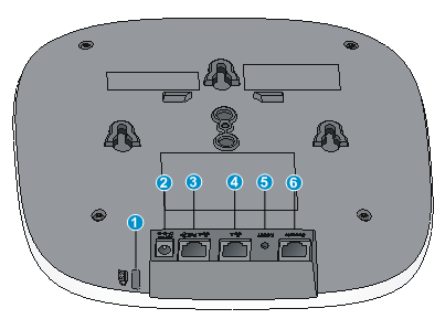
(1) Security slot | (2) Power port |
(3) 10/100/1000 Mbps copper Ethernet port 1 | (4) 10/100/1000 Mbps copper Ethernet port 2 |
(5) Reset button | (6) Console port |
Table 4 Port description
Port mark | Standards and protocols | Description |
ETH1 | · IEEE802.3 · IEEE802.3u · IEEE802.3af | The Ethernet port can act as an uplink interface to access the Internet or MAN, and as a PoE port at the same time. It is represented by interface GE1/0/1. |
ETH2 | · IEEE802.3 · IEEE802.3u | The Ethernet port can act as an uplink interface to access the Internet or MAN. It is represented by interface GE1/0/2. |
DC 48V | N/A | The port receives +48 VDC power from the local supply. |
CONSOLE | RS/EIA-232 | The console port is used for configuration and management. When the AP acts as a fit AP, only the maintenance staff can use the console port. |
A
accessories for AP installation, 3
AP
ceiling-mounting, 9
connecting console cable, 14
console port access, 14, 16
installation, 5, 6
installation accessories, 3
LEDs, 18
logging, 14
ports, 18
setting configuration environment, 14
setting terminal parameters, 15
Telnet access, 17
wall-mounting, 6
Web access, 17
B
bits per second (parameter), 15
C
cable
connecting console, 14
ceiling-mounting
AP, 9
check after power-on, 12
check before installation, 5
check before power-on, 11
configuring
AP, 14
connecting
console cable, 14
local power supply, 12
network, 13
PoE power supply, 11
power supply, 11
console
connecting cable, 14
D
data bits (parameter), 15
determining installation position, 6
E
electrical
connecting console cable, 14
connecting local power supply, 12
connecting PoE power supply, 11
connecting power supply, 11
emulation (parameter), 15
environment
site humidity, 3
site temperature, 3
equipment needed for installation, 4
F
flow control (parameter), 15
H
hardware
AP installation, 5, 6
port technical specifications, 18
humidity (installation site), 3
I
installation position
determining, 6
installing
AP, 5, 6
equipment, 4
safety recommendations, 3
site humidity, 3
site temperature, 3
tools, 4
L
LED
technical specifications, 18
local power supply
AP, 12
logging
AP, 14
logging through console port
AP, 14, 16
logging through Telnet
AP, 17
logging through Web
AP, 17
login
AP, 14
N
network connection verification
fat AP, 13
fit AP, 13
networking
AP, 13
P
parity (parameter), 15
PoE power supply
AP, 11
port
technical specifications, 18
post-power-on
check, 12
power supply
AP, 11
pre-installation
check, 5
preparing for installation, 3
pre-power-on
check, 11
procedure
connecting AP to network, 13
connecting local power supply, 12
connecting PoE power supply, 11
connecting power supply, 11
installing AP, 5, 6
installing the AP on a ceiling, 9
mounting the AP on a wall, 6
verifying network connection for the fat AP, 13
verifying network connection for the fit AP, 13
product overview, 1
S
safety
installation site humidity, 3
installation site temperature, 3
recommendations, 3
setting
AP configuration environment, 14
terminal parameters, 15
site
humidity, 3
temperature, 3
stop bits (parameter), 15
T
technical specifications
LED, 18
port, 18
temperature
installation site requirements, 3
tools needed for installation, 4
V
verifying
network connection for the fat AP, 13
network connection for the fit AP, 13
VT100, 15
W
wall-mounting
AP, 6