- Table of Contents
-
- 02-Layer 2-LAN Switching Configuration Guide
- 00-Preface
- 01-Ethernet interface configuration
- 02-Loopback and null interface configuration
- 03-Bulk interface configuration
- 04-MAC address table configuration
- 05-Ethernet link aggregation configuration
- 06-Port isolation configuration
- 07-Spanning tree configuration
- 08-BPDU tunneling configuration
- 09-VLAN configuration
- 10-GVRP configuration
- 11-LLDP configuration
- 12-Service loopback group configuration
- 13-MVRP configuration
- Related Documents
-
| Title | Size | Download |
|---|---|---|
| 09-VLAN configuration | 516.75 KB |
Configuring basic VLAN settings
Configuring basic settings of a VLAN interface
Introduction to port-based VLAN
Assigning an access port to a VLAN
Assigning a trunk port to a VLAN
Assigning a hybrid port to a VLAN
Introduction to MAC-based VLAN
Configuration restrictions and guidelines
Configuring protocol-based VLANs
Configuring IP subnet-based VLANs
Displaying and maintaining VLANs
Configuring a VLAN interface for the super VLAN
Displaying and maintaining super VLANs
Super VLAN configuration example
Configuring isolate-user-VLANs
Configuration restrictions and guidelines
Displaying and maintaining isolate-user-VLANs
Isolate-user-VLAN configuration example
Configuration example for configuring the uplink port to permit multiple isolate-user-VLANs
Security mode and normal mode of voice VLANs
Configuration restrictions and guidelines
Configuring QoS priority settings for voice traffic on an interface
Configuration restrictions and guidelines
Configuring a port to operate in automatic voice VLAN assignment mode
Configuring a port to operate in manual voice VLAN assignment mode
Displaying and maintaining voice VLANs
Voice VLAN configuration examples
Automatic voice VLAN assignment mode configuration example
Manual voice VLAN assignment mode configuration example
This chapter describes how to configure VLANs.
Overview
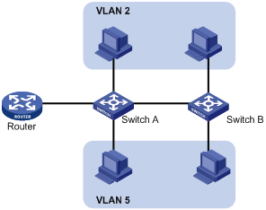
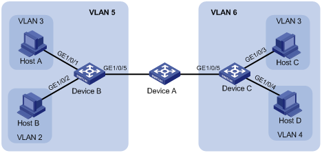
Ethernet is a shared-media network based on the CSMA/CD mechanism. A local area network (LAN) built by using Ethernet is both a collision domain and a broadcast domain. In a LAN with plenty of hosts, the LAN may be full of collisions and broadcasts, and the LAN performance is degraded or even becomes unavailable. You can deploy bridges or Layer 2 switches in the LAN to reduce the collisions, but this cannot confine broadcasts. To address the issue, virtual LAN (VLAN) was introduced to break a LAN down into separate VLANs. Hosts in the same VLAN can directly communicate, and hosts of different VLANs cannot directly communicate. For example, hosts in VLAN 2 can communicate with each other, but cannot communicate with the hosts in VLAN 5. A VLAN is a broadcast domain, and contains all broadcast traffic within it, as shown in Figure 1.
A VLAN is logically divided on an organizational basis rather than on a physical basis. For example, using VLAN, all workstations and servers that a particular workgroup uses can be assigned to the same VLAN, regardless of their physical locations.
VLAN technology delivers the following benefits:
· Confining broadcast traffic within individual VLANs. This reduces bandwidth waste and improves network performance.
· Improving LAN security. By assigning user groups to different VLANs, you can isolate them at Layer 2. To enable communication between VLANs, routers or Layer 3 switches are required.
· Creating flexible virtual workgroups. Because users from the same workgroup can be assigned to the same VLAN regardless of their physical locations, network construction and maintenance are much easier and more flexible.
VLAN frame encapsulation
In order that a Layer 2 switch can identify frames of different VLANs, a VLAN tag field is inserted into the data link layer encapsulation.
The format of VLAN-tagged frames is defined in IEEE 802.1Q issued in 1999.
As shown in Figure 2, in the header of a traditional Ethernet packet, the field after the destination MAC address and the source MAC address (DA & SA) field is the Type field, which indicates the upper layer protocol type.
Figure 2 Traditional Ethernet packet format
![]()
IEEE 802.1Q inserts a four-byte VLAN tag between the DA & SA field and the Type field to identify the VLAN information, as shown in Figure 3.
Figure 3 Position and format of VLAN tag
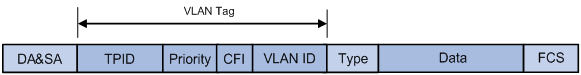
The fields of a VLAN tag are TPID, priority, CFI, and VLAN ID.
· TPID—The 16-bit TPID field indicates whether a frame is VLAN-tagged. By default, the TPID value is 0x8100, which indicates that the frame is VLAN-tagged. Devices vendors can set the TPID to different values. For compatibility with these devices, modify the TPID value so that frames carry a TPID value identical to the value of a particular vendor, allowing interoperability with devices from that vendor. The device determines whether a received frame carries a VLAN tag by checking the TPID value. When the TPID value of a frame is the configured value or 0x8100, the frame is considered as a VLAN-tagged frame. For information about commands used to modify TPID values, see Layer 2—LAN Switching Command Reference.
· Priority—The 3-bit priority field indicates the 802.1p priority of the frame.
· CFI—The 1-bit CFI field indicates whether the MAC addresses are encapsulated in standard format when packets are transmitted across different media. A value of 0 indicates that MAC addresses are encapsulated in standard format. A value of 1 indicates that MAC addresses are encapsulated in a non-standard format. The value of this field is 0 by default.
· VLAN ID—The 12-bit VLAN ID field identifies the VLAN that the frame belongs to. The VLAN ID range is 0 to 4095. Because 0 and 4095 are reserved, a VLAN ID actually ranges from 1 to 4094.
A network device handles an incoming frame depending on whether the frame is VLAN tagged and the value of the VLAN tag, if any. For more information, see "Introduction to port-based VLAN."
Ethernet supports encapsulation formats Ethernet II, 802.3/802.2 LLC, 802.3/802.2 SNAP, and 802.3 raw. The Ethernet II encapsulation format is used here. For how the VLAN tag fields are added to frames encapsulated in these formats for VLAN identification, see related protocols and standards.
When a frame carrying multiple VLAN tags passes through, the device processes the frame according to its outer VLAN tag, and transmits the inner tags as payload.
VLAN types
You can implement VLANs based on the following criteria:
· Port
· MAC address
· Protocol
· IP subnet
· Policy
· Other criteria
This chapter covers port-based VLAN, MAC-based VLAN, protocol-based VLAN, and IP subnet-based VLAN. The port-based VLAN implementation is the basis of all other VLAN implementations. To use any other VLAN implementations, you must configure port-based VLAN settings.
You can configure these types of VLANs on a port at the same time. When the device is determining which VLAN a packet that passes through the port should be assigned to, it looks up the VLANs in the default order of MAC-based VLAN, IP subnet-based VLAN, protocol-based VLAN, and port-based VLAN.
Protocols and standards
IEEE 802.1Q, IEEE Standards for Local and Metropolitan Area Networks: Virtual Bridged Local Area Networks
Configuring basic VLAN settings
When you configure basic VLAN settings, follow these guidelines:
· As the default VLAN, VLAN 1 cannot be created or removed.
· You cannot manually create or remove VLANs reserved for special purposes.
· To remove a protocol reserved VLAN, voice VLAN, management VLAN, dynamic VLAN, VLAN with a QoS policy applied, control VLAN for a smart link group, control VLAN for an RRPP domain, or remote probe VLAN for remote port mirroring, remove the configuration from the VLAN first, and execute the undo vlan command.
To configure basic VLAN settings:
|
Step |
Command |
Remarks |
|
1. Enter system view. |
system-view |
N/A |
|
2. Create a VLAN and enter its view, or create VLANs in batch. |
vlan { vlan-id1 [ to vlan-id2 ] | all } |
Optional. By default, only the default VLAN (VLAN 1) exists in the system. |
|
3. Enter VLAN view. |
vlan vlan-id |
Required only when you create VLANs in bulk. |
|
4. Configure a name for the VLAN. |
name text |
Optional. The default name is VLAN vlan-id, which is the ID of the VLAN. For example, the name of VLAN 100 is VLAN 0100 by default. |
|
5. Configure the description of the VLAN. |
description text |
Optional. The default description is VLAN vlan-id, which is the ID of the VLAN. For example, the description of VLAN 100 is VLAN 0100 by default. |
Configuring basic settings of a VLAN interface
You can use VLAN interfaces to provide Layer 3 communication between hosts of different VLANs. VLAN interfaces are virtual interfaces used for Layer 3 communication between different VLANs. They do not exist as physical entities on devices. For each VLAN, you can create one VLAN interface. You can assign the VLAN interface an IP address and specify the IP address as the gateway address for the devices in the VLAN, so that traffic can be routed to other IP subnets.
Configuration procedure
Before you create a VLAN interface for a VLAN, you must create the VLAN.
To configure basic settings of a VLAN interface:
|
Step |
Command |
Remarks |
|
1. Enter system view. |
system-view |
N/A |
|
2. Create a VLAN interface and enter VLAN interface view. |
interface vlan-interface vlan-interface-id |
If the specified VLAN interface already exists, you enter its view directly. |
|
3. Assign an IP address to the VLAN interface. |
ip address ip-address { mask | mask-length } [ sub ] |
Optional. By default, no IP address is assigned to any VLAN interface. |
|
4. Configure the description of the VLAN interface. |
description text |
Optional. By default, the description of a VLAN is the VLAN interface name. For example, Vlan-interface1 Interface. |
|
5. Set the MTU for the VLAN interface. |
mtu size |
Optional. By default, the MTU is 1500 bytes. |
|
6. Restore the default settings for the VLAN interface. |
default |
Optional. |
|
7. Cancel the action of manually shutting down the VLAN interface. |
undo shutdown |
Optional. By default, a VLAN interface is not manually shut down. The VLAN interface is up if one or more ports in the VLAN is up, and goes down if all ports in the VLAN go down. |
Configuration example
Network requirements
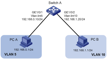
As shown in Figure 4, PC A is assigned to VLAN 5. PC B is assigned to VLAN 10. The PCs belong to different IP subnets and cannot communicate with each other.
Configure VLAN interfaces on Switch A and configure the PC A and PC B to enable Layer 3 communication between them.
Configuration procedure
1. Configure Switch A:
# Create VLAN 5 and assign GigabitEthernet 1/0/1 to it.
<SwitchA> system-view
[SwitchA] vlan 5
[SwitchA-vlan5] port GigabitEthernet 1/0/1
# Create VLAN 10 and assign GigabitEthernet 1/0/2 to it.
[SwitchA-vlan5] vlan 10
[SwitchA-vlan10] port GigabitEthernet 1/0/2
[SwitchA-vlan10] quit
# Create VLAN-interface 5 and configure its IP address as 192.168.0.10/24.
[SwitchA] interface vlan-interface 5
[SwitchA-Vlan-interface5] ip address 192.168.0.10 24
[SwitchA-Vlan-interface5] quit
# Create VLAN-interface 10 and configure its IP address as 192.168.1.20/24.
[SwitchA] interface vlan-interface 10
[SwitchA-Vlan-interface10] ip address 192.168.1.20 24
[SwitchA-Vlan-interface10] return
2. Configure the default gateway of PC A as 192.168.0.10.
3. Configure the default gateway of PC B as 192.168.1.20.
Verifying the configuration
1. The PCs can ping each other.
2. Display brief information about Layer 3 interfaces on Switch A to verify the configuration.
<SwitchA> display ip interface brief
*down: administratively down
(s): spoofing (l): loopback
Interface Physical Protocol IP Address Description
Vlan-interface5 up up 192.168.0.10 Vlan-inte...
Vlan-interface10 up up 192.168.1.20 Vlan-inte...
Configuring port-based VLANs
This section describes how to configure port-based VLANs.
Introduction to port-based VLAN
Port-based VLANs group VLAN members by port. A port forwards traffic for a VLAN only after it is assigned to the VLAN.
Port link type
You can configure the link type of a port as access, trunk, or hybrid. The link types use the following VLAN tag handling methods:
· An access port belongs to only one VLAN and sends traffic untagged.
It is usually used to connect a terminal device unable to identify VLAN-tagged packets or when it is unnecessary to separate different VLAN members.
· A trunk port can carry multiple VLANs to receive and send traffic for them.
Except traffic from the PVID, traffic sent through a trunk port will be VLAN tagged. Usually, ports that connect network devices are configured as trunk ports.
· A hybrid port allows traffic of some VLANs to pass through untagged and traffic of some other VLANs to pass through tagged. You can configure a port connected to a network device or user terminal as a hybrid port.
PVID
By default, VLAN 1 is the port VLAN ID (PVID) for all ports. You can configure the PVID for a port as required.
When you configure the PVID on a port, use the following guidelines:
· An access port can join only one VLAN. The VLAN to which the access port belongs is the PVID of the port.
· A trunk or hybrid port can join multiple VLANs, and you can configure a PVID for the port.
· You can use a nonexistent VLAN as the PVID for a hybrid or trunk port, but not for an access port. After you use the undo vlan command to delete the VLAN where an access port resides, the PVID of the port changes to VLAN 1. However, the removal of the VLAN specified as the PVID of a trunk or hybrid port does not affect the PVID setting on the port.
When you configure the PVID, follow these guidelines:
· Do not set the voice VLAN as the PVID of a port in automatic voice VLAN assignment mode. For information about voice VLAN, see "Configuring voice VLANs."
· H3C recommends that you set the same PVID for local and remote ports.
· Make sure that a port permits the traffic from its PVID to pass through. Otherwise, when the port receives frames tagged with the PVID or untagged frames, the port drops these frames.
Frame handling on a port
The following table shows how ports of different link types handle frames:
|
Actions |
Access |
Trunk |
Hybrid |
|
|
Incoming untagged frame |
Tags the frame with the PVID tag. |
Determines whether the PVID is permitted on the port, as follows: · If yes, tags the frame with the PVID tag. · If not, drops the frame. |
||
|
Incoming tagged frame |
· Receives the frame if its VLAN ID is the same as the PVID. · Drops the frame if its VLAN ID is different from the PVID. |
· Receives the frame if its VLAN is permitted on the port. · Drops the frame if its VLAN is not permitted on the port. |
||
|
Outgoing frames |
Removes the VLAN tag and sends the frame. |
· Removes the tag and sends the frame if the frame carries the PVID tag and the port belongs to the PVID. · Sends the frame without removing the tag if its VLAN is carried on the port but is different from the PVID. |
Sends the frame if its VLAN is permitted on the port. The frame is sent with the VLAN tag removed or intact depending on your configuration with the port hybrid vlan command. This is true of the PVID. |
|
Assigning an access port to a VLAN
You can assign an access port to a VLAN in VLAN view or interface view. Before you assign an access port to a VLAN, you must create the VLAN.
In VLAN view, you can assign only Layer 2 Ethernet interfaces to the VLAN.
To assign one or multiple access ports to a VLAN in VLAN view:
|
Step |
Command |
Remarks |
|
1. Enter system view |
system-view |
N/A |
|
2. Enter VLAN view |
vlan vlan-id |
N/A |
|
3. Assign one or a group of access ports to the VLAN |
port interface-list |
By default, all ports belong to VLAN 1. |
To assign an access port to a VLAN in interface view:
|
Step |
Command |
Remarks |
|
1. Enter system view. |
system-view |
N/A |
|
2. Enter interface view or port group view. |
·
Enter Layer 2 Ethernet interface view: ·
Enter Layer 2 aggregation interface view: ·
Enter port group view: |
Use one of the commands. · The configuration made in Layer 2 Ethernet interface view applies only to the port. · The configuration made in port group view applies to all ports in the port group. · The configuration made in Layer 2 aggregate interface view applies to the aggregate interface and its aggregation member ports. If the system fails to apply the configuration to the aggregate interface, it stops applying the configuration to aggregation member ports. If the system fails to apply the configuration to an aggregation member port, it skips the port and moves to the next member port. |
|
3. Configure the link type of the ports as access. |
port link-type access |
Optional. By default, all ports are access ports. |
|
4. Assign the access ports to a VLAN. |
port access vlan vlan-id |
Optional. By default, all access ports belong to VLAN 1. |
Assigning a trunk port to a VLAN
A trunk port can carry multiple VLANs. You can assign it to a VLAN in interface view.
Configuration restrictions and guidelines
· To change the link type of a port from trunk to hybrid or from hybrid to trunk, you must set the link type to access first.
· After configuring the PVID for a trunk port, you must use the port trunk permit vlan command to configure the trunk port to allow packets from the PVID to pass through, so that the egress port can forward packets from the PVID.
Configuration procedure
To assign a trunk port to one or multiple VLANs:
|
Step |
Command |
Remarks |
|
1. Enter system view. |
system-view |
N/A |
|
2. Enter interface view or port group view. |
·
Enter Layer 2 Ethernet interface view: ·
Enter Layer 2 aggregation interface view: ·
Enter port group view: |
Use one of the commands. · The configuration made in Ethernet interface view applies only to the port. · The configuration made in port group view applies to all ports in the port group. · The configuration made in Layer 2 aggregate interface view applies to the aggregate interface and its aggregation member ports. If the system fails to apply the configuration to the aggregate interface, it stops applying the configuration to aggregation member ports. If the system fails to apply the configuration to an aggregation member port, it skips the port and moves to the next member port. |
|
3. Configure the link type of the ports as trunk. |
port link-type trunk |
By default, all ports are access ports. |
|
4. Assign the trunk ports to the specified VLANs. |
port trunk permit vlan { vlan-list | all } |
By default, a trunk port carries only VLAN 1. |
|
5. Configure the PVID of the trunk ports. |
port trunk pvid vlan vlan-id |
Optional. By default, the PVID is VLAN 1. |
Assigning a hybrid port to a VLAN
A hybrid port can carry multiple VLANs. You can assign it to a VLAN in interface view.
Configuration restrictions and guidelines
· To change the link type of a port from trunk to hybrid or from hybrid to trunk, you must set the link type to access first.
· Before assigning a hybrid port to a VLAN, create the VLAN first.
· After you configure the PVID for a hybrid port, you must use the port hybrid vlan command to configure the hybrid port to allow packets from the PVID to pass through, so that the egress port can forward packets from the PVID.
Configuration procedure
To assign a hybrid port to one or multiple VLANs:
|
Step |
Command |
Remarks |
|
1. Enter system view. |
system-view |
N/A |
|
2. Enter interface view or port group view. |
·
Enter Layer 2 Ethernet interface view: ·
Enter Layer 2 aggregation interface view: ·
Enter port group view: |
Use one of the commands. · The configuration made in Ethernet interface view applies only to the port. · The configuration made in port group view applies to all ports in the port group. · The configuration made in Layer 2 aggregate interface view applies to the aggregate interface and its aggregation member ports. If the system fails to apply the configuration to the aggregate interface, it stops applying the configuration to aggregation member ports. If the system fails to apply the configuration to an aggregation member port, it skips the port and moves to the next member port. |
|
3. Configure the link type of the ports as hybrid. |
port link-type hybrid |
By default, all ports are access ports. |
|
4. Assign the hybrid ports to the specified VLANs. |
port hybrid vlan vlan-list { tagged | untagged } |
By default, a hybrid port allows only packets of VLAN 1 to pass through untagged. |
|
5. Configure the PVID of the hybrid ports. |
port hybrid pvid vlan vlan-id |
Optional. By default, the PVID is VLAN 1. |
Configuration example
Network requirements
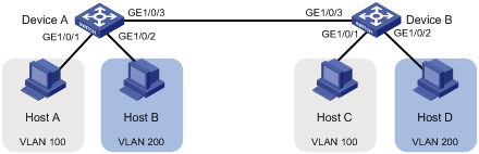
As shown in Figure 5, Host A and Host C belong to Department A, and access the enterprise network through different devices. Host B and Host D belong to Department B. They also access the enterprise network through different devices.
To ensure communication security and avoid broadcast storms, VLANs are configured in the enterprise network to isolate Layer 2 traffic of different departments. VLAN 100 is assigned to Department A, and VLAN 200 is assigned to Department B.
Make sure that hosts within the same VLAN can communicate with each other. Host A can communicate with Host C, and Host B can communicate with Host D.
Configuration procedure
1. Configure Device A:
# Create VLAN 100, and assign port GigabitEthernet 1/0/1 to VLAN 100.
<DeviceA> system-view
[DeviceA] vlan 100
[DeviceA-vlan100] port gigabitethernet 1/0/1
[DeviceA-vlan100] quit
# Create VLAN 200, and assign port GigabitEthernet 1/0/2 to VLAN 200.
[DeviceA] vlan 200
[DeviceA-vlan200] port gigabitethernet 1/0/2
[DeviceA-vlan200] quit
# Configure port GigabitEthernet 1/0/3 as a trunk port, and assign it to VLANs 100 and 200, to enable GigabitEthernet 1/0/3 to forward traffic of VLANs 100 and 200 to Device B.
[DeviceA] interface gigabitethernet 1/0/3
[DeviceA-GigabitEthernet1/0/3] port link-type trunk
[DeviceA-GigabitEthernet1/0/3] port trunk permit vlan 100 200
Please wait... Done.
2. Configure Device B:
Configure Device B as you configure Device A.
3. Configure hosts:
Configure Host A and Host C to be on the same IP subnet, 192.168.100.0/24, for example. Configure Host B and Host D to be on the same IP subnet, 192.168.200.0/24, for example.
Verifying the configuration
1. Host A and Host C can ping each other successfully, but they both fail to ping Host B. Host B and Host D can ping each other successfully, but they both fail to ping Host A.
2. Determine whether the configuration is successful by displaying relevant VLAN information.
# Display information about VLANs 100 and 200 on Device A.
[DeviceA-GigabitEthernet1/0/3] display vlan 100
VLAN ID: 100
VLAN Type: static
Route Interface: not configured
Description: VLAN 0100
Name: VLAN 0100
Tagged Ports:
GigabitEthernet1/0/3
Untagged Ports:
GigabitEthernet1/0/1
[DeviceA-GigabitEthernet1/0/3] display vlan 200
VLAN ID: 200
VLAN Type: static
Route Interface: not configured
Description: VLAN 0200
Name: VLAN 0200
Tagged Ports:
GigabitEthernet1/0/3
Untagged Ports:
GigabitEthernet1/0/2
Configuring MAC-based VLANs
This section describes how to configure MAC-based VLANs.
Introduction to MAC-based VLAN
The MAC-based VLAN feature assigns hosts to a VLAN based on their MAC addresses. This feature is usually used in conjunction with security technologies such as 802.1X to provide secure, flexible network access for terminal devices.
Static MAC-based VLAN assignment
Static MAC-based VLAN assignment applies to networks containing a small number of VLAN users. In such a network, you can create a MAC address-to-VLAN map containing multiple MAC address-to-VLAN entries on a port, enable the MAC-based VLAN feature on the port, and assign the port to MAC-based VLANs.
With static MAC-based VLAN assignment configured on a port, the device processes received frames by using the following guidelines:
· When the port receives an untagged frame, the device looks up the MAC address-to-VLAN map based on the source MAC address of the frame for a match.
¡ The device first performs a fuzzy match. In the fuzzy match, the device searches the MAC address-to-VLAN entries whose masks are not all-Fs and performs a logical AND operation on the source MAC address and each mask. If the result of an AND operation matches the corresponding MAC address, the device tags the frame with the corresponding VLAN ID.
¡ If the fuzzy match fails, the device performs an exact match. In the exact match, the device searches the MAC address-to-VLAN entries whose masks are all-Fs. If the MAC address of a MAC address-to-VLAN entry matches the source MAC address of the untagged frame, the device tags the frame with the corresponding VLAN ID.
¡ If no match is found, the device assigns a VLAN to the frame by using other criteria, such as IP subnet or protocol, and forwards the frame.
¡ If no VLAN is available, the device tags the frame with the PVID of the receiving port and forwards the frame.
· When the port receives a tagged frame, the port forwards the frame if the VLAN ID of the frame is permitted by the port. Otherwise, it drops the frame.
Dynamic MAC-based VLAN assignment
When you cannot determine the target MAC-based VLANs of a port, you can use dynamic MAC-based VLAN assignment on the port. To do that, you can create a MAC address-to-VLAN map containing multiple MAC address-to-VLAN entries, and enable the MAC-based VLAN feature and dynamic MAC-based VLAN assignment on the port.
Dynamic MAC-based VLAN assignment uses the following workflows.
1. When the port receives a frame, it first determines whether the frame is tagged.
¡ If yes, the port reports the source MAC address of the frame.
¡ If not, the port selects a VLAN for the frame in the order of MAC-based VLAN, IP subnet-based VLAN, protocol-based VLAN, and port-based VLAN, tags the untagged frame with the selected VLAN tag, and obtains the tag. Then, the port reports the source MAC address of the frame.
2. After reporting the source MAC address of the frame, the port looks up the source MAC address in the MAC-to-VLAN map, and processes the frame as follows:
¡ If the source MAC address of the frame exactly matches a MAC address-to-VLAN entry configured on the port, the port checks whether the VLAN ID of the frame is the same as the VLAN in the MAC address-to-VLAN entry.
If yes, the port dynamically joins the VLAN and forwards the frame.
If not, the port drops the frame.
¡ If the source MAC address of the frame does not exactly match any MAC address-to-VLAN entry, the port processes the frame depending on whether the VLAN ID of the frame is the PVID.
If yes, the port determines whether it allows PVID: if yes, the port forwards the frame within the PVID; if not, the port drops the frame.
If not, the port assigns a VLAN to the frame by using other criteria, such as IP subnet or protocol, and forwards the frame. If no VLAN is available, the port drops the frame.
Figure 6 Flowchart for processing a frame in dynamic MAC-based VLAN assignment

When you configure dynamic MAC-based VLAN assignment, follow these guidelines:
· When a port is assigned to the corresponding VLAN in a MAC address-to-VLAN entry, but has not been assigned to the VLAN by using the port hybrid vlan command, the port sends packets from the VLAN with VLAN tags removed.
· If you configure both static and dynamic MAC-based VLAN assignment on the same port, dynamic MAC-based VLAN assignment applies.
· When a packet matches a MAC address-to-VLAN entry, the device picks a forwarding policy for the packet according to the 802.1p priority mapped to the MAC address.
Configuration restrictions and guidelines
When you configure MAC-based VLAN, follow these guidelines:
· MAC-based VLANs are available only on hybrid ports.
· Do not configure a super VLAN as the VLAN of a MAC address-to-VLAN entry.
· With dynamic MAC-based VLAN assignment enabled, packets are delivered to the CPU for processing. The packet processing mode has the highest priority and overrides the configuration of MAC learning limit and disabling of MAC address learning. When dynamic MAC-based VLAN assignment is enabled, do not configure the MAC learning limit or disable MAC address learning.
· Do not use dynamic MAC-based VLAN assignment together with 802.X and MAC authentication.
· In dynamic MAC-based VLAN assignment, the port that receives a packet with an unknown source MAC address can be successfully assigned to the matched VLAN only when the matched VLAN is a static VLAN.
· The MAC-based VLAN feature is mainly configured on downlink ports of user access devices. Do not enable this function together with link aggregation.
· With MSTP enabled, if a port is blocked in the MST instance (MSTI) of the target MAC-based VLAN, the port drops received packets instead of delivering them to the CPU. As a result, the receiving port will not be dynamically assigned to the corresponding VLAN. Do not configure dynamic MAC-based VLAN assignment together with MSTP, because the former is mainly configured on the access side.
· With PVST enabled, if the target MAC-based VLAN is not permitted on a port, the port is placed in the blocked state and drops received packets instead of delivering them to the CPU. As a result, the receiving port will not be dynamically assigned to the corresponding VLAN. Do not configure dynamic MAC-based VLAN assignment together with PVST, because the former is mainly configured on the access side.
Configuration procedure
This section describes the MAC-based VLAN configuration procedure.
Configuring static MAC-based VLAN assignment
|
Step |
Command |
Remarks |
|
1. Enter system view. |
system-view |
N/A |
|
2. Associate a specific MAC address with a VLAN. |
mac-vlan mac-address mac-address [ mask mac-mask ] vlan vlan-id [ priority priority ] |
N/A |
|
3. Enter interface view or port group view. |
·
Enter interface view: ·
Enter port group view: |
Use one of the commands. · The configuration made in Ethernet interface view applies only to the port. · The configuration made in port group view applies to all ports in the port group. |
|
4. Configure the link type of the ports as hybrid. |
port link-type hybrid |
By default, all ports are access ports. |
|
5. Configure the hybrid ports to permit packets from specific MAC-based VLANs to pass through. |
port hybrid vlan vlan-list { tagged | untagged } |
By default, a hybrid port only permits packets from VLAN 1 to pass through. |
|
6. Enable the MAC-based VLAN feature. |
mac-vlan enable |
By default, MAC-based VLAN is disabled. |
|
7. Configure VLAN matching precedence. |
vlan precedence { mac-vlan | ip-subnet-vlan } |
Optional. By default, VLANs are preferably matched based on MAC addresses. |
Configuring dynamic MAC-based VLAN assignment
|
Step |
Command |
Remarks |
|
1. Enter system view. |
system-view |
N/A |
|
2. Associate MAC addresses with a VLAN. |
mac-vlan mac-address mac-address vlan vlan-id [ priority priority ] |
With dynamic MAC-based VLAN assignment enabled, a port is automatically assigned to the VLAN in the MAC address-to-VLAN entry that is exactly matched by the source MAC address of the packet received on the port. |
|
3. Enter Ethernet interface view. |
interface interface-type interface-number |
N/A |
|
4. Configure the link type of the port as hybrid. |
port link-type hybrid |
By default, all ports are access ports. |
|
5. Enable the MAC-based VLAN feature. |
mac-vlan enable |
By default, MAC-based VLAN is disabled. |
|
6. Enable dynamic MAC-based VLAN assignment. |
mac-vlan trigger enable |
By default, dynamic MAC-based VLAN assignment is disabled. |
|
7. Configure VLAN matching precedence. |
vlan precedence mac-vlan |
Optional. By default, VLANs are preferentially matched based on MAC addresses. |
|
8. Disable the PVID of the port from forwarding packets with unknown source MAC addresses that do not match any MAC address-to-VLAN entry. |
port pvid disable |
Optional. By default, when a port receives a packet with an unknown source MAC address that does not match any MAC address-to-VLAN entry, it forwards the packet in its PVID. |
When you use the mac-vlan trigger enable command to enable dynamic MAC-based VLAN assignment, H3C recommends that you configure the vlan precedence mac-vlan command, so that VLANs are assigned based on single MAC addresses preferentially. When dynamic MAC-based VLAN assignment is enabled, H3C does not recommend configuring the vlan precedence ip-subnet-vlan command, which will make the system assign VLANs based on IP subnets, because the configuration does not take effect.
Dynamic MAC-based VLAN assignment works only when an exact match is found, or in other words, when the source MAC address of an untagged incoming packet matches a MAC address-to-VLAN entry whose mask is all Fs. In this case, the port adds the source MAC address to its MAC address table, and automatically joins the matched VLAN. Dynamic MAC-based VLAN assignment does not work when no match or a fuzzy match (mask of the matched entry is not all Fs) is found.
Configuration example
Network requirements
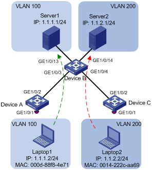
As shown in Figure 7:
· GigabitEthernet 1/0/1 of Device A and Device C are each connected to a meeting room. Laptop 1 and Laptop 2 are used for meetings and might be used in either of the two meeting rooms.
· Different departments own Laptop 1 and Laptop 2. The two departments use VLAN 100 and VLAN 200, respectively.
· The MAC address of Laptop 1 is 000D-88F8-4E71, and that of Laptop 2 is 0014-222C-AA69.
Configure MAC-based VLANs, so that each laptop is able to access only its own department server, no matter which meeting room it is used in.
Configuration considerations
· Create VLANs 100 and 200.
· Configure the uplink ports of Device A and Device C as trunk ports, and assign them to VLANs 100 and 200.
· Configure the downlink ports of Device B as trunk ports, and assign them to VLANs 100 and 200. Assign the uplink ports of Device B to VLANs 100 and 200.
· Associate the MAC address of Laptop 1 with VLAN 100, and associate the MAC address of Laptop 2 with VLAN 200.
Configuration procedure
1. Configure Device A:
# Create VLANs 100 and 200.
<DeviceA> system-view
[DeviceA] vlan 100
[DeviceA-vlan100] quit
[DeviceA] vlan 200
[DeviceA-vlan200] quit
# Associate the MAC address of Laptop 1 with VLAN 100, and associate the MAC address of Laptop 2 with VLAN 200.
[DeviceA] mac-vlan mac-address 000d-88f8-4e71 vlan 100
[DeviceA] mac-vlan mac-address 0014-222c-aa69 vlan 200
# Configure GigabitEthernet 1/0/1 as a hybrid port that sends packets of VLANs 100 and 200 untagged, and enable the MAC-based VLAN feature on it, so that Laptop 1 and Laptop 2 can access the network through GigabitEthernet 1/0/1.
[DeviceA] interface gigabitethernet 1/0/1
[DeviceA-GigabitEthernet1/0/1] port link-type hybrid
[DeviceA-GigabitEthernet1/0/1] port hybrid vlan 100 200 untagged
Please wait... Done.
[DeviceA-GigabitEthernet1/0/1] mac-vlan enable
[DeviceA-GigabitEthernet1/0/1] quit
# To enable the laptops to access Server 1 and Server 2, configure the uplink port GigabitEthernet 1/0/2 as a trunk port, and assign it to VLANs 100 and 200.
[DeviceA] interface gigabitethernet 1/0/2
[DeviceA-GigabitEthernet1/0/2] port link-type trunk
[DeviceA-GigabitEthernet1/0/2] port trunk permit vlan 100 200
[DeviceA-GigabitEthernet1/0/2] quit
2. Configure Device B:
# Create VLANs 100 and 200. Assign GigabitEthernet 1/0/13 to VLAN 100, and assign GigabitEthernet 1/0/14 to VLAN 200.
<DeviceB> system-view
[DeviceB] vlan 100
[DeviceB-vlan100] port gigabitethernet 1/0/13
[DeviceB-vlan100] quit
[DeviceB] vlan 200
[DeviceB-vlan200] port gigabitethernet 1/0/14
[DeviceB-vlan200] quit
# Configure GigabitEthernet 1/0/3 and GigabitEthernet 1/0/4 as trunk ports, and assign them to VLANs 100 and 200.
[DeviceB] interface gigabitethernet 1/0/3
[DeviceB-GigabitEthernet1/0/3] port link-type trunk
[DeviceB-GigabitEthernet1/0/3] port trunk permit vlan 100 200
[DeviceB-GigabitEthernet1/0/3] quit
[DeviceB] interface gigabitethernet 1/0/4
[DeviceB-GigabitEthernet1/0/4] port link-type trunk
[DeviceB-GigabitEthernet1/0/4] port trunk permit vlan 100 200
[DeviceB-GigabitEthernet1/0/4] quit
3. Configure Device C:
Configure Device C as you configure Device A.
Verifying the configuration
1. Laptop 1 can access only Server 1, and Laptop 2 can access only Server 2.
2. On Device A and Device C, you can see that VLAN 100 is associated with the MAC address of Laptop 1, and VLAN 200 is associated with the MAC address of Laptop 2.
[DeviceA] display mac-vlan all
The following MAC VLAN addresses exist:
S:Static D:Dynamic
MAC ADDR MASK VLAN ID PRIO STATE
--------------------------------------------------------
000d-88f8-4e71 ffff-ffff-ffff 100 0 S
0014-222c-aa69 ffff-ffff-ffff 200 0 S
Total MAC VLAN address count:2
Configuration guidelines
1. MAC-based VLAN can be configured only on hybrid ports.
2. MAC-based VLAN is usually configured on downlink ports of access layer devices, and cannot be configured together with the link aggregation function.
Configuring protocol-based VLANs
The protocol-based VLAN feature assigns packets to VLANs by their application type. This feature assigns inbound packets to different VLANs based on their protocol type and encapsulation format. The protocols available for VLAN assignment include IP, IPX, and AT, and the encapsulation formats include Ethernet II, 802.3 raw, 802.2 LLC, and 802.2 SNAP.
A protocol template defines a protocol type and an encapsulation format. The combination of a protocol-based VLAN ID and a protocol index can uniquely identify a protocol template. You can assign multiple protocol templates to a protocol-based VLAN.
Protocol-based VLAN assignment is available only on hybrid ports, and a protocol template applies only to untagged packets.
When an untagged packet arrives, a protocol-based VLAN assignment enabled hybrid port processes the packet by using the following workflow:
· If the protocol type and encapsulation format in the packet matches a protocol template, the packet is tagged with the VLAN tag specific to the protocol template.
· If no protocol template is matched, the packet is tagged with the PVID of the port.
The port processes a tagged packet as it processes tagged packets of a port-based VLAN.
· If the port is in the same VLAN as the packet, it forwards the packet.
· If not, the port drops the packet.
Configuration procedure
|
|
CAUTION: A protocol-based VLAN processes only untagged inbound packets, whereas the voice VLAN in automatic mode processes only tagged voice traffic. Do not configure a VLAN as both a protocol-based VLAN and a voice VLAN. For more information, see "Configuring voice VLANs." |
To configure a protocol-based VLAN:
|
Step |
Command |
Remarks |
|
1. Enter system view. |
system-view |
N/A |
|
2. Enter VLAN view. |
vlan vlan-id |
If the specified VLAN does not exist, this command creates the VLAN first. |
|
3. Create a protocol template for the VLAN. |
protocol-vlan [ protocol-index ] { at | ipv4 | ipx { ethernetii | llc | raw | snap } | mode { ethernetii etype etype-id | llc { dsap dsap-id [ ssap ssap-id ] | ssap ssap-id } | snap etype etype-id } } |
By default, no protocol template is configured for a VLAN. |
|
4. Exit VLAN view. |
quit |
N/A |
|
5. Enter interface view or port group view. |
·
Enter Ethernet interface view: ·
Enter Layer 2 aggregation interface view: ·
Enter port group view: |
Use one of the commands. · The configuration made in Ethernet interface view applies only to the port. · The configuration made in port group view applies to all ports in the port group. · The configuration made in Layer 2 aggregate interface view applies to the aggregate interface and its aggregation member ports. If the system fails to apply the configuration to the aggregate interface, it stops applying the configuration to aggregation member ports. If the system fails to apply the configuration to an aggregation member port, it skips the port and moves to the next member port. |
|
6. Configure the port link type as hybrid. |
port link-type hybrid |
By default, all ports are access ports. |
|
7. Assign the hybrid port to the specified protocol-based VLANs. |
port hybrid vlan vlan-list { tagged | untagged } |
By default, a hybrid port is only in VLAN 1. |
|
8. Assign the protocol template you have created to the hybrid port. |
port hybrid protocol-vlan vlan vlan-id { protocol-index [ to protocol-end ] | all } |
N/A |
Configuring IP subnet-based VLANs
In this approach, packets are assigned to VLANs based on their source IP addresses and subnet masks. A port configured with IP subnet-based VLANs assigns an incoming untagged packet to a VLAN based on the source address of the packet.
This feature assigns packets from a specified IP subnet or IP address to a specific VLAN.
Configuration procedure
The IP subnet-based VLAN feature is available only for hybrid ports.
To configure an IP subnet-based VLAN:
|
Step |
Command |
Remarks |
|
1. Enter system view. |
system-view |
N/A |
|
2. Enter VLAN view. |
vlan vlan-id |
N/A |
|
3. Associate an IP subnet with the VLAN. |
ip-subnet-vlan [ ip-subnet-index ] ip ip-address [ mask ] |
The IP subnet or IP address to be associated with a VLAN cannot be a multicast subnet or a multicast address. |
|
4. Return to system view. |
quit |
N/A |
|
5. Enter interface view or port group view. |
·
Enter Ethernet interface view: ·
Enter Layer 2 aggregation interface view: ·
Enter port group view: |
Use one of the commands. · The configuration made in Ethernet interface view applies only to the port. · The configuration made in port group view applies to all ports in the port group. · The configuration made in Layer 2 aggregate interface view applies to the aggregate interface and its aggregation member ports. If the system fails to apply the configuration to the aggregate interface, it stops applying the configuration to aggregation member ports. If the system fails to apply the configuration to an aggregation member port, it skips the port and moves to the next member port. |
|
6. Configure port link type as hybrid. |
port link-type hybrid |
By default, all ports are access ports. |
|
7. Configure the hybrid ports to permit the specified IP subnet-based VLANs to pass through. |
port hybrid vlan vlan-list { tagged | untagged } |
By default, a hybrid port allows only packets from VLAN 1 to pass through untagged. |
|
8. Associate the hybrid ports with the specified IP subnet-based VLAN. |
port hybrid ip-subnet-vlan vlan vlan-id |
By default, no IP subnet-based VLAN is associated with a port. |
Configuration example
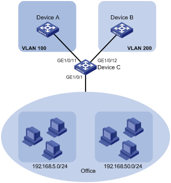
Network requirements
As shown in Figure 8, the hosts in the office belong to different IP subnets 192.168.5.0/24 and 192.168.50.0/24.
Configure Device C to transmit packets over separate VLANs based on their source IP addresses.
Configuration considerations
· Create VLANs 100 and 200.
· Associate IP subnets with the VLANs.
· Assign ports to the VLANs.
Configuration procedure
# Associate IP subnet 192.168.5.0/24 with VLAN 100.
<DeviceC> system-view
[DeviceC] vlan 100
[DeviceC-vlan100] ip-subnet-vlan ip 192.168.5.0 255.255.255.0
[DeviceC-vlan100] quit
# Associate IP subnet 192.168.50.0/24 with VLAN 200.
[DeviceC] vlan 200
[DeviceC-vlan200] ip-subnet-vlan ip 192.168.50.0 255.255.255.0
[DeviceC-vlan200] quit
# Configure interface GigabitEthernet 1/0/11 to permit packets of VLAN 100 to pass through.
[DeviceC] interface gigabitethernet 1/0/11
[DeviceC-GigabitEthernet1/0/11] port link-type hybrid
[DeviceC-GigabitEthernet1/0/11] port hybrid vlan 100 tagged
Please wait... Done.
[DeviceC-GigabitEthernet1/0/11] quit
# Configure interface GigabitEthernet 1/0/12 to permit packets of VLAN 200 to pass through.
[DeviceC] interface gigabitethernet 1/0/12
[DeviceC-GigabitEthernet1/0/12] port link-type hybrid
[DeviceC-GigabitEthernet1/0/12] port hybrid vlan 200 tagged
Please wait... Done.
[DeviceC-GigabitEthernet1/0/12] quit
# Associate interface GigabitEthernet 1/0/1 with IP subnet-based VLANs 100 and 200.
[DeviceC] interface gigabitethernet 1/0/1
[DeviceC-GigabitEthernet1/0/1] port link-type hybrid
[DeviceC-GigabitEthernet1/0/1] port hybrid vlan 100 200 untagged
Please wait... Done.
[DeviceC-GigabitEthernet1/0/1] port hybrid ip-subnet-vlan vlan 100
[DeviceC-GigabitEthernet1/0/1] port hybrid ip-subnet-vlan vlan 200
[DeviceC-GigabitEthernet1/0/1] return
Verifying the configuration
# Display IP subnet information for all VLANs.
<Device C> display ip-subnet-vlan vlan all
VLAN ID: 100
Subnet Index IP Address Subnet Mask
====================================================
0 192.168.5.0 255.255.255.0
VLAN ID: 200
Subnet Index IP Address Subnet Mask
====================================================
0 192.168.50.0 255.255.255.0
# Display IP subnet-based VLAN information on GigabitEthernet 1/0/1.
<DeviceC> display ip-subnet-vlan interface gigabitethernet 1/0/1
Interface: GigabitEthernet1/0/1
VLAN ID Subnet-Index IP ADDRESS NET MASK
=======================================================
100 0 192.168.5.0 255.255.255.0
200 0 192.168.50.0 255.255.255.0
Configuration guidelines
IP subnet-based VLAN configurations are only effective on hybrid ports.
Displaying and maintaining VLANs
|
Task |
Command |
Remarks |
|
Display VLAN information. |
display vlan [ vlan-id1 [ to vlan-id2 ] | all | dynamic | reserved | static ] [ | { begin | exclude | include } regular-expression ] |
Available in any view. |
|
Display VLAN interface information. |
display interface [ vlan-interface ] [ brief [ down ] ] [ | { begin | exclude | include } regular-expression ] display interface vlan-interface vlan-interface-id [ brief ] [ | { begin | exclude | include } regular-expression ] |
Available in any view. |
|
Display hybrid ports or trunk ports on the device. |
display port { hybrid | trunk } [ | { begin | exclude | include } regular-expression ] |
Available in any view. |
|
Display MAC address-to-VLAN entries. |
display mac-vlan { all | dynamic | mac-address mac-address [ mask mac-mask ] | static | vlan vlan-id } [ | { begin | exclude | include } regular-expression ] |
Available in any view. |
|
Display all interfaces with MAC-based VLAN enabled. |
display mac-vlan interface [ | { begin | exclude | include } regular-expression ] |
Available in any view. |
|
Display protocol information and protocol indexes of the specified VLANs. |
display protocol-vlan vlan { vlan-id [ to vlan-id ] | all } [ | { begin | exclude | include } regular-expression ] |
Available in any view. |
|
Display protocol-based VLAN information on specified interfaces. |
display protocol-vlan interface { interface-type interface-number [ to interface-type interface-number ] | all } [ | { begin | exclude | include } regular-expression ] |
Available in any view. |
|
Display IP subnet-based VLAN information and IP subnet indexes of specified VLANs. |
display ip-subnet-vlan vlan { vlan-id1 [ to vlan-id2 ] | all } [ | { begin | exclude | include } regular-expression ] |
Available in any view. |
|
Display IP subnet-based VLAN information and IP subnet indexes of specified ports. |
display ip-subnet-vlan interface { interface-list | all } [ | { begin | exclude | include } regular-expression ] |
Available in any view. |
|
Clear statistics on a port. |
reset counters interface vlan-interface [ vlan-interface-id ] |
Available in user view. |
Super VLAN, also called VLAN aggregation, was introduced to save IP address space.
A super VLAN is associated with multiple sub-VLANs. You can create a VLAN interface for a super VLAN and assign an IP address for the VLAN interface. However, you cannot create a VLAN interface for a sub-VLAN. You can assign a physical port to a sub-VLAN, but not to a super VLAN. All ports of a sub-VLAN use the VLAN interface IP address of the associated super VLAN. Packets cannot be forwarded between sub-VLANs at Layer 2.
To enable Layer 3 communication between sub-VLANs, create a super VLAN and the VLAN interface, and enable local proxy ARP on the VLAN interface. After the configuration, the super VLAN can forward and process ARP requests and replies.
Configuration procedure
To configure a super VLAN, complete the following tasks:
1. Configure sub-VLANs.
2. Configure a super VLAN, and associate the super VLAN with the sub-VLANs configured earlier.
3. Configure a VLAN interface for the super VLAN. The VLAN interface enables communication among hosts and sub-VLANs.
Configuring sub-VLANs
To configure more sub-VLANs, repeat the following steps.
To configure a sub-VLAN:
|
Step |
Command |
Remarks |
|
1. Enter system view. |
system-view |
N/A |
|
2. Create a sub-VLAN and enter VLAN view. |
vlan vlan-id |
If the specified VLAN already exists, this command enters VLAN view only. |
Configuring a super VLAN
When you configure a super VLAN, follow these guidelines:
· On a port configured with dynamic MAC-based VLAN assignment, you cannot configure the VLAN of a MAC address-to-VLAN entry as a super VLAN.
· Do not configure a VLAN as a super VLAN and a sub VLAN at the same time.
To configure a super VLAN:
|
Step |
Command |
Remarks |
|
1. Enter system view. |
system-view |
N/A |
|
2. Enter VLAN view. |
vlan vlan-id |
If the specified VLAN does not exist, this command creates the VLAN first, and then enters VLAN view. |
|
3. Configure the VLAN as a super VLAN. |
supervlan |
By default, no super VLAN is configured. |
|
4. Associate the super VLAN with the specified sub-VLANs. |
subvlan vlan-list |
VLANs specified by vlan-list must be the sub-VLANs configured earlier. |
Configuring a VLAN interface for the super VLAN
This section describes how to configure a VLAN interface for the super VLAN.
To configure a VLAN interface for the super VLAN:
|
Step |
Command |
Remarks |
|
1. Enter system view. |
system-view |
N/A |
|
2. Create a VLAN interface, and enter VLAN interface view. |
interface vlan-interface vlan-interface-id |
The value of vlan-interface-id must be the ID of the super VLAN. |
|
3. Configure an IP address for the VLAN interface of the super VLAN. |
ip address ip-address { mask | mask-length } [ sub ] |
By default, the IP address of a VLAN interface is not configured. |
|
4. Enable local proxy ARP. |
local-proxy-arp enable |
By default, local proxy ARP is disabled. |
Displaying and maintaining super VLANs
|
Task |
Command |
Remarks |
|
Display the mapping between a super VLAN and its sub-VLANs. |
display supervlan [ supervlan-id ] [ | { begin | exclude | include } regular-expression ] |
Available in any view. |
Super VLAN configuration example
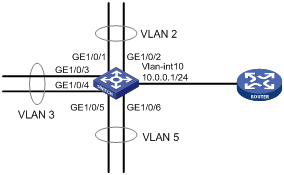
Network requirements
As shown in Figure 9:
· Create super VLAN 10, and configure its VLAN interface IP address as 10.0.0.1/24.
· Create sub-VLANs VLAN 2, VLAN 3, and VLAN 5.
· Assign GigabitEthernet 1/0/1 and GigabitEthernet 1/0/2 to VLAN 2, GigabitEthernet 1/0/3 and GigabitEthernet 1/0/4 to VLAN 3, and GigabitEthernet 1/0/5 and GigabitEthernet 1/0/6 to VLAN 5.
· The sub-VLANs are isolated at Layer 2 but connected at Layer 3.
Configuration procedure
# Create VLAN 10, and configure its VLAN interface IP address as 10.0.0.1/24.
<Sysname> system-view
[Sysname] vlan 10
[Sysname-vlan10] quit
[Sysname] interface vlan-interface 10
[Sysname-Vlan-interface10] ip address 10.0.0.1 255.255.255.0
# Enable local proxy ARP.
[Sysname-Vlan-interface10] local-proxy-arp enable
[Sysname-Vlan-interface10] quit
# Create VLAN 2, and assign GigabitEthernet 1/0/1 and GigabitEthernet 1/0/2 to it.
[Sysname] vlan 2
[Sysname-vlan2] port gigabitethernet 1/0/1 gigabitethernet 1/0/2
[Sysname-vlan2] quit
# Create VLAN 3, and assign GigabitEthernet 1/0/3 and GigabitEthernet 1/0/4 to it.
[Sysname] vlan 3
[Sysname-vlan3] port gigabitethernet 1/0/3 gigabitethernet 1/0/4
[Sysname-vlan3] quit
# Create VLAN 5, and assign GigabitEthernet 1/0/5 and GigabitEthernet 1/0/6 to it.
[Sysname] vlan 5
[Sysname-vlan5] port gigabitethernet 1/0/5 gigabitethernet 1/0/6
[Sysname-vlan5] quit
# Configure VLAN 10 as the super VLAN, and configure VLAN 2, VLAN 3, and VLAN 5 as its sub-VLANs.
[Sysname] vlan 10
[Sysname-vlan10] supervlan
[Sysname-vlan10] subvlan 2 3 5
[Sysname-vlan10] quit
[Sysname] quit
Verifying the configuration
# Display information about VLAN 10, the super VLAN, to verify the configuration.
<Sysname> display supervlan
SuperVLAN ID : 10
SubVLAN ID : 2-3 5
VLAN ID: 10
VLAN Type: static
It is a Super VLAN.
Route Interface: configured
Ip Address: 10.0.0.1
Subnet Mask: 255.255.255.0
Description: VLAN 0010
Name: VLAN 0010
Tagged Ports: none
Untagged Ports: none
VLAN ID: 2
VLAN Type: static
It is a Sub VLAN.
Route Interface: configured
Ip Address: 10.0.0.1
Subnet Mask: 255.255.255.0
Description: VLAN 0002
Name: VLAN 0002
Tagged Ports: none
Untagged Ports:
GigabitEthernet1/0/1 GigabitEthernet1/0/2
VLAN ID: 3
VLAN Type: static
It is a Sub VLAN.
Route Interface: configured
Ip Address: 10.0.0.1
Subnet Mask: 255.255.255.0
Description: VLAN 0003
Name: VLAN 0003
Tagged Ports: none
Untagged Ports:
GigabitEthernet1/0/3 GigabitEthernet1/0/4
VLAN ID: 5
VLAN Type: static
It is a Sub VLAN.
Route Interface: configured
Ip Address: 10.0.0.1
Subnet Mask: 255.255.255.0
Description: VLAN 0005
Name: VLAN 0005
Tagged Ports: none
Untagged Ports:
GigabitEthernet1/0/5 GigabitEthernet1/0/6
An isolate-user-VLAN uses a two-tier VLAN structure. In this approach, both an isolate-user-VLAN and secondary VLANs are configured on the same device.
The isolate-user-VLAN implementation delivers the following benefits:
· Isolate-user-VLANs are mainly used for upstream data exchange. An isolate-user-VLAN can be associated with multiple secondary VLANs. Because the upstream device identifies only the isolate-user-VLAN and not the secondary VLANs, network configuration is simplified and VLAN resources are saved.
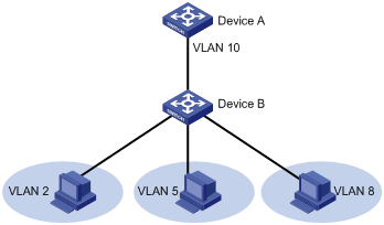
· You can isolate Layer 2 traffic from different users by assigning ports connected to them to different secondary VLANs. To enable communication between secondary VLANs associated with the same isolate-user-VLAN, you can enable local proxy ARP on the upstream device (such as Device A in Figure 10) to realize Layer 3 communication between the secondary VLANs.
As shown in Figure 10, the isolate-user-VLAN function is enabled on Device B. VLAN 10 is the isolate-user-VLAN. VLAN 2, VLAN 5, and VLAN 8 are secondary VLANs associated with VLAN 10 and are invisible to Device A.
Figure 10 An isolate-user-VLAN example
Configuration restrictions and guidelines
When you configure an isolate-user-VLAN, follow these guidelines:
· To enable users in the isolate-user-VLAN to communicate with other networks at Layer 3, configure VLAN interfaces for the isolate-user-VLAN and the secondary VLANs, and configure the gateway IP address for the isolate-user-VLAN interface (you do not need to configure IP addresses for the secondary VLAN interfaces).
· You cannot configure the member port of a service loopback group as the uplink or downlink port of an isolate-user-VLAN. For more information about the service loopback group, see "Configuring service loopback groups."
· The port isolate-user-vlan vlan-list trunk promiscuous command and the port isolate-user-vlan vlan-id promiscuous command are mutually exclusive. The two commands are different as follows:
¡ The former configures a port to permit packets from multiple isolate-user-VLANs to pass through.
¡ The latter configures a port to permit packets from only one isolate-user-VLAN to pass through.
Configuration procedure
To configure an isolate-user-VLAN, complete the following tasks:
1. Configure the isolate-user-VLAN.
2. Configure the secondary VLANs.
3. Associate the isolate-user-VLAN with the specified secondary VLANs.
4. Configure uplink and downlink ports in the following workflow:
a. Configure the uplink ports, for example, the port connecting Device B to Device A in Figure 10, to operate in promiscuous mode in the specified VLAN, so that uplink ports can be automatically added to the specified isolate-user-VLAN and the secondary VLANs associated with the isolate-user-VLAN.
b. Configure the downlink ports, for example, the ports connecting Device B to hosts in Figure 10, to operate in host mode, so that downlink ports can be automatically added to the isolate-user-VLAN associated with the secondary VLAN.
For more information about the promiscuous and host mode commands, see Layer 2—LAN Switching Command Reference.
To configure an isolate-user-VLAN:
|
Step |
Command |
Remarks |
|
1. Enter system view. |
system-view |
N/A |
|
2. Create a VLAN and enter VLAN view. |
vlan vlan-id |
N/A |
|
3. Configure the VLAN as an isolate-user-VLAN. |
isolate-user-vlan enable |
By default, no isolate-user-VLAN is configured. |
|
4. Return to system view. |
quit |
N/A |
|
5. Create secondary VLANs. |
vlan { vlan-id1 [ to vlan-id2 ] | all } |
N/A |
|
6. Configure Layer 2 isolation between ports in the same secondary VLAN. |
isolated-vlan enable |
Optional. By default, ports in the same secondary VLAN can communicate with one another at Layer 2. This configuration takes effect only after you configure all ports in the same secondary VLAN to operate in host mode and associate secondary VLANs with an isolate-user-VLAN. |
|
7. Return to system view. |
quit |
N/A |
|
8. Associate the isolate-user-VLAN with the specified secondary VLANs. |
isolate-user-vlan isolate-user-vlan-id secondary secondary-vlan-id [ to secondary-vlan-id ] |
By default, no isolate-user-VLAN is associated with secondary VLANs. |
|
9. Configure the uplink port for the isolate-user-VLAN. |
a.
Enter Layer 2 Ethernet or aggregate interface
view: b.
Configure the port to operate in
promiscuous mode in a specific VLAN or a list of VLANs: |
By default, a port does not operate in promiscuous mode or host mode in a VLAN. |
|
10. Return to system view. |
quit |
N/A |
|
11. Configure a downlink port for the isolate-user-VLAN. |
a.
Enter Layer 2 Ethernet or aggregate interface
view: b.
(Optional.) Configure the link type of the port: c.
Assign the port to secondary VLANs (use one of
the commands depending on the link type): d.
Configure the port to operate in host
mode: |
By default, a port is an access port that does not operate in host mode or promiscuous mode. |
|
12. Return to system view. |
quit |
N/A |
Displaying and maintaining isolate-user-VLANs
|
Task |
Command |
Remarks |
|
Display the mapping between an isolate-user-VLAN and its secondary VLANs. |
display isolate-user-vlan [ isolate-user-vlan-id ] [ | { begin | exclude | include } regular-expression ] |
Available in any view. |
Isolate-user-VLAN configuration example
Network requirements
As shown in Figure 11, connect Device A to downstream devices Device B and Device C.
Configure VLAN 5 on Device B as an isolate-user-VLAN, assign uplink port GigabitEthernet 1/0/5 to VLAN 5, and associate VLAN 5 with secondary VLANs VLAN 2 and VLAN 3. Assign GigabitEthernet 1/0/2 to VLAN 2 and GigabitEthernet 1/0/1 to VLAN 3.
Configure VLAN 6 on Device C as an isolate-user-VLAN, assign uplink port GigabitEthernet 1/0/5 to VLAN 6, and associate VLAN 6 with secondary VLANs VLAN 3 and VLAN 4. Assign GigabitEthernet 1/0/3 to VLAN 3 and GigabitEthernet 1/0/4 to VLAN 4.
As far as Device A is concerned, Device B only has VLAN 5 and Device C only has VLAN 6.
Configuration procedure
The following procedure provides only details about the configuration on Device B and Device C.
1. Configure Device B:
# Configure the isolate-user-VLAN.
<DeviceB> system-view
[DeviceB] vlan 5
[DeviceB-vlan5] isolate-user-vlan enable
[DeviceB-vlan5] quit
# Create secondary VLANs.
[DeviceB] vlan 2 to 3
# Associate the isolate-user-VLAN with the secondary VLANs.
[DeviceB] isolate-user-vlan 5 secondary 2 to 3
# Configure uplink port GigabitEthernet 1/0/5 to operate in promiscuous mode in VLAN 5.
[DeviceB] interface gigabitethernet 1/0/5
[DeviceB-GigabitEthernet1/0/5] port isolate-user-vlan 5 promiscuous
[DeviceB-GigabitEthernet1/0/5] quit
# Assign downlink ports GigabitEthernet 1/0/1 and GigabitEthernet 1/0/2 to VLAN 3 and VLAN 2, respectively, and configure the ports to operate in host mode.
[DeviceB] interface gigabitethernet 1/0/1
[DeviceB-GigabitEthernet1/0/1] port access vlan 3
[DeviceB-GigabitEthernet1/0/1] port isolate-user-vlan host
[DeviceB-GigabitEthernet1/0/1] quit
[DeviceB] interface gigabitethernet 1/0/2
[DeviceB-GigabitEthernet1/0/2] port access vlan 2
[DeviceB-GigabitEthernet1/0/2] port isolate-user-vlan host
[DeviceB-GigabitEthernet1/0/2] quit
2. Configure Device C:
# Configure the isolate-user-VLAN.
<DeviceC> system-view
[DeviceC] vlan 6
[DeviceC-vlan6] isolate-user-vlan enable
[DeviceC-vlan6] quit
# Create secondary VLANs.
[DeviceC] vlan 3 to 4
# Associate the isolate-user-VLAN with the secondary VLANs.
[DeviceC] isolate-user-vlan 6 secondary 3 to 4
# Configure uplink port GigabitEthernet 1/0/5 to operate in promiscuous mode in VLAN 6.
[DeviceC] interface gigabitethernet 1/0/5
[DeviceC-GigabitEthernet1/0/5] port isolate-user-vlan 6 promiscuous
[DeviceC-GigabitEthernet1/0/5] quit
# Configure downlink ports GigabitEthernet 1/0/3 and GigabitEthernet 1/0/4 to VLAN 3 and VLAN 4, respectively, and configure the ports to operate in host mode.
[DeviceC] interface gigabitethernet 1/0/3
[DeviceC-GigabitEthernet1/0/3] port access vlan 3
[DeviceC-GigabitEthernet1/0/3] port isolate-user-vlan host
[DeviceC-GigabitEthernet1/0/3] quit
[DeviceC] interface gigabitethernet 1/0/4
[DeviceC-GigabitEthernet1/0/4] port access vlan 4
[DeviceC-GigabitEthernet1/0/4] port isolate-user-vlan host
[DeviceC-GigabitEthernet1/0/4] quit
Verifying the configuration
# Display the isolate-user-VLAN configuration on Device B.
[DeviceB] display isolate-user-vlan
Isolate-user-VLAN VLAN ID : 5
Secondary VLAN ID : 2-3
VLAN ID: 5
VLAN Type: static
Isolate-user-VLAN type : isolate-user-VLAN
Route Interface: not configured
Description: VLAN 0005
Name: VLAN 0005
Tagged Ports: none
Untagged Ports:
GigabitEthernet1/0/1 GigabitEthernet1/0/2 GigabitEthernet1/0/5
VLAN ID: 2
VLAN Type: static
Isolate-user-VLAN type : secondary
Route Interface: not configured
Description: VLAN 0002
Name: VLAN 0002
Tagged Ports: none
Untagged Ports:
GigabitEthernet1/0/2 GigabitEthernet1/0/5
VLAN ID: 3
VLAN Type: static
Isolate-user-VLAN type : secondary
Route Interface: not configured
Description: VLAN 0003
Name: VLAN 0003
Tagged Ports: none
Untagged Ports:
GigabitEthernet1/0/1 GigabitEthernet1/0/5
Configuration example for configuring the uplink port to permit multiple isolate-user-VLANs
Network requirements
As shown in Figure 12, Device B is attached to Device A.
Configure the isolate-user-VLAN feature, so that:
· VLAN 5 and VLAN 10 are isolate-user-VLANs on Device B. The uplink port GigabitEthernet 1/0/1 permits packets from VLANs 5 and 10 to pass through tagged.
· On Device B, the downlink port GigabitEthernet 1/0/2 permits secondary VLAN 2 and the downlink port GigabitEthernet 1/0/3 permits VLAN 3. Secondary VLANs 2 and 3 are associated with isolate-user-VLAN 5.
· On Device B, the downlink port GigabitEthernet 1/0/6 permits secondary VLAN 6 and the downlink port GigabitEthernet 1/0/8 permits VLAN 8. Secondary VLANs 6 and 8 are associated with isolate-user-VLAN 10.
· Device A identifies only VLANs 5 and 10 on Device B.

Configuration procedure
1. Configure Device B:
# Configure VLAN 5 and VLAN 10 as isolate-user-VLANs.
<DeviceB> system-view
[DeviceB] vlan 5
[DeviceB-vlan5] isolate-user-vlan enable
[DeviceB-vlan5] quit
[DeviceB] vlan 10
[DeviceB-vlan10] isolate-user-vlan enable
[DeviceB-vlan10] quit
# Create VLANs 2, 3, 6, and 8.
[DeviceB] vlan 2 to 3
[DeviceB] vlan 6
[DeviceB-vlan6] quit
[DeviceB] vlan 8
[DeviceB-vlan8] quit
# Associate secondary VLANs 2 and 3 with isolate-user-VLAN 5.
[DeviceB] isolate-user-vlan 5 secondary 2 to 3
# Associate secondary VLANs 6 and 8 with isolate-user-VLAN 10.
[DeviceB] isolate-user-vlan 10 secondary 6 8
# Configure the uplink port GigabitEthernet 1/0/1 to operate in promiscuous mode in VLANs 5 and 10.
[DeviceB] interface gigabitethernet 1/0/1
[DeviceB-GigabitEthernet1/0/1] port isolate-user-vlan 5 10 trunk promiscuous
[DeviceB-GigabitEthernet1/0/1] quit
# Assign the downlink port GigabitEthernet 1/0/2 to VLAN 2, and configure the port to operate in host mode in VLAN 2. Assign the downlink port GigabitEthernet 1/0/3 to VLAN 3, and configure the port to operate in host mode in VLAN 3.
[DeviceB] interface gigabitethernet 1/0/2
[DeviceB-GigabitEthernet1/0/2] port access vlan 2
[DeviceB-GigabitEthernet1/0/2] port isolate-user-vlan host
[DeviceB-GigabitEthernet1/0/2] quit
[DeviceB] interface gigabitethernet 1/0/3
[DeviceB-GigabitEthernet1/0/3] port access vlan 3
[DeviceB-GigabitEthernet1/0/3] port isolate-user-vlan host
[DeviceB-GigabitEthernet1/0/3] quit
# Assign the downlink port GigabitEthernet 1/0/6 to VLAN 6, and configure the port to operate in host mode in VLAN 6. Assign the downlink port GigabitEthernet 1/0/8 to VLAN 8, and configure the port to operate in host mode in VLAN 8.
[DeviceB] interface gigabitethernet 1/0/6
[DeviceB-GigabitEthernet1/0/6] port access vlan 6
[DeviceB-GigabitEthernet1/0/6] port isolate-user-vlan host
[DeviceB-GigabitEthernet1/0/6] quit
[DeviceB] interface gigabitethernet 1/0/8
[DeviceB-GigabitEthernet1/0/8] port access vlan 8
[DeviceB-GigabitEthernet1/0/8] port isolate-user-vlan host
[DeviceB-GigabitEthernet1/0/8] quit
2. Configure Device A:
# Create VLAN 5 and VLAN 10.
[DeviceA] vlan 5
[DeviceA-vlan5] quit
[DeviceA] vlan 10
[DeviceA-vlan10] quit
# Configure GigabitEthernet 1/0/1 as a hybrid port, and configure the port to permit the packets from VLAN 5 and VLAN 10 to pass through tagged.
[DeviceA] interface gigabitethernet 1/0/1
[DeviceA-GigabitEthernet1/0/1] port link-type hybrid
[DeviceA-GigabitEthernet1/0/1] port hybrid vlan 5 10 tagged
[DeviceA-GigabitEthernet1/0/1] quit
Verifying the configuration
# Display the configuration of isolate-user-VLAN 5. (The output for isolate-user-VLAN 10 is similar.)
[DeviceB] display isolate-user-vlan 5
Isolate-user-VLAN VLAN ID : 5
Secondary VLAN ID : 2-3
VLAN ID: 5
VLAN Type: static
Isolate-user-VLAN type : isolate-user-VLAN
Route Interface: not configured
Description: VLAN 0005
Name: VLAN 0005
Tagged Ports:
GigabitEthernet1/0/1
Untagged Ports:
GigabitEthernet1/0/2 GigabitEthernet1/0/3
VLAN ID: 2
VLAN Type: static
Isolate-user-VLAN type : secondary
Route Interface: not configured
Description: VLAN 0002
Name: VLAN 0002
Tagged Ports:
GigabitEthernet1/0/1
Untagged Ports:
GigabitEthernet1/0/2
VLAN ID: 3
VLAN Type: static
Isolate-user-VLAN type : secondary
Route Interface: not configured
Description: VLAN 0003
Name: VLAN 0003
Tagged Ports:
GigabitEthernet1/0/1
Untagged Ports:
GigabitEthernet1/0/3
This chapter describes how to configure voice VLANs.
Overview
A voice VLAN is configured for voice traffic. After assigning the ports that connect to voice devices to a voice VLAN, the system automatically configures QoS parameters for voice traffic, to improve the transmission priority of voice traffic and ensure voice quality.
Common voice devices include IP phones and integrated access devices (IADs). Only IP phones are used in the voice VLAN configuration examples in this document.
OUI addresses
A device determines whether a received packet is a voice packet by evaluating its source MAC address. A packet whose source MAC address complies with the Organizationally Unique Identifier (OUI) address of the voice device is regarded as voice traffic.
In general, as the first 24 bits of a MAC address (in binary format), an OUI address is a globally unique identifier that IEEE assigns to a vendor. In this document, however, OUI addresses are addresses that the system uses to determine whether a received packet is a voice packet. They are the results of the AND operation of the arguments mac-address and oui-mask in the voice vlan mac-address command.
You can manually remove the default OUI address of a device and then add new ones. You can configure the OUI addresses of a device in advance or use the default OUI addresses. Table 1 lists the default OUI address for each vendor's devices.
Table 1 The default OUI addresses of different vendors
|
Number |
OUI address |
Vendor |
|
|
|
1 |
0001-E300-0000 |
Siemens phone |
||
|
2 |
0003-6B00-0000 |
Cisco phone |
||
|
3 |
0004-0D00-0000 |
Avaya phone |
||
|
4 |
00D0-1E00-0000 |
Pingtel phone |
||
|
5 |
0060-B900-0000 |
Philips/NEC phone |
||
|
6 |
00E0-7500-0000 |
Polycom phone |
||
|
7 |
00E0-BB00-0000 |
3Com phone |
||
Voice VLAN assignment modes
A port can be assigned to a voice VLAN in one of the following modes:
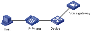
· Automatic mode—The system matches the source MAC address carried in protocol packets sent when an IP phone is powered on against the device's OUI addresses. If the system finds a match, it automatically assigns the receiving port to the voice VLAN, issues ACL rules and configures the packet precedence. You can configure a voice VLAN aging time on the device. The system will remove a port from the voice VLAN if no packets are received from the port during the aging time. The system automatically assigns ports to, or removes ports from, a voice VLAN. Automatic mode is suitable for scenarios where PCs and IP phones connected in series access the network through the device and ports on the device transmit both voice traffic and data traffic at the same time, as shown in Figure 13. When the voice VLAN works normally, if the system reboots, the system reassigns ports in automatic voice VLAN assignment mode to the voice VLAN after reboot, ensuring that existing voice connections can work normally. In this case, voice traffic streams do not trigger port assignment to the voice VLAN.
Figure 13 PCs and IP phones connected in series access the network
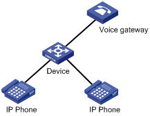
· Manual mode—You must manually assign an IP phone accessing port to a voice VLAN. Then, the system matches the source MAC addresses carried in packets against the device's OUI addresses. If the system finds a match, it issues ACL rules and configures the packet precedence. In this mode, you must manually assign ports to, or remove ports from, a voice VLAN. Manual mode is suitable for scenarios where only IP phones access the network through the device, and ports on the device transmit only voice traffic, as shown in Figure 14. In this mode, ports assigned to a voice VLAN transmit voice traffic exclusively, which prevents data traffic from impacting the transmission of voice traffic.
Figure 14 Only IP phones access the network
Both modes forward tagged packets sent out of IP phones according to their tags. Table 2 and Table 3 list the configurations required for ports of different link types to support tagged or untagged voice traffic sent from IP phones when different voice VLAN assignment modes are configured.
When IP phones send untagged voice traffic, the voice traffic receiving ports must operate in manual voice VLAN assignment mode. To implement the voice VLAN feature, you must also configure the PVID of each receiving port as the voice VLAN. As a result, you cannot implement 802.1X authentication.
Table 2 Required configurations on ports of different link types for supporting tagged voice traffic
|
Port link type |
Voice VLAN assignment modes supported for tagged voice traffic |
Configuration requirements |
|
Access |
N/A |
N/A |
|
Trunk |
Automatic and manual |
In automatic mode, the PVID of the port cannot be the voice VLAN. In manual mode, the PVID of the port cannot be the voice VLAN. Configure the port to permit packets of the voice VLAN to pass through. |
|
Hybrid |
Automatic and manual |
In automatic mode, the PVID of the port cannot be the voice VLAN. In manual mode, the PVID of the port cannot be the voice VLAN. Configure the port to permit packets of the voice VLAN to pass through tagged. |
Table 3 Required configurations on ports of different link types for supporting tagged voice traffic
|
Port link type |
Voice VLAN assignment mode supported for untagged voice traffic |
Configuration requirements |
|
Access |
Manual |
Configure the PVID of the port as the voice VLAN. |
|
Trunk |
Manual |
Configure the PVID of the port as the voice VLAN and assign the port to the voice VLAN. |
|
Hybrid |
Manual |
Configure the PVID of the port as the voice VLAN and configure the port to permit packets of the voice VLAN to pass through untagged. |
Security mode and normal mode of voice VLANs
Depending on their inbound packet filtering mechanisms, voice VLAN-enabled ports can operate in the one of the following modes:
· Normal mode—Voice VLAN-enabled ports receive packets that carry the voice VLAN tag and forward packets in the voice VLAN without comparing their source MAC addresses against the OUI addresses configured for the device. If the PVID of the port is the voice VLAN and the port operates in manual VLAN assignment mode, the port forwards all received untagged packets in the voice VLAN. In normal mode, voice VLANs are vulnerable to traffic attacks. Malicious users may send large quantities of forged voice VLAN-tagged or untagged packets to consume all of the voice VLAN bandwidth, affecting normal voice communication.
· Security mode—Only voice packets whose source MAC addresses match the recognizable OUI addresses can pass through the voice VLAN-enabled inbound port, but all other packets are dropped.
In a safe network, you can configure the voice VLANs to operate in normal mode, which reduces system resources used for checking source MAC addresses. Table 4 shows how a voice VLAN-enabled port processes packets in security and normal mode.
H3C does not recommend transmitting both voice traffic and non-voice traffic in a voice VLAN. If you must transmit both voice traffic and nonvoice traffic, make sure that the voice VLAN security mode is disabled.
Table 4 How a voice VLAN-enabled port processes packets in security and normal mode
|
Voice VLAN mode |
Packet processing mode |
|
Security mode |
·
For untagged packets and packets that carry
the voice VLAN tag: ·
For packets that carry other tags: |
|
Normal mode |
·
For untagged packets and packets that carry
the voice VLAN tag: ·
For packets that carry other tags: |
Configuration prerequisites
Before you configure a voice VLAN, complete the following tasks:
· Create a VLAN.
· Configure QoS priority settings for voice VLAN traffic on an interface before enabling voice VLAN on the interface.
If the configuration order is reversed, your priority configuration will fail. For more information, see "Configuring QoS priority settings for voice traffic on an interface."
· Configure the voice VLAN assignment mode.
For more information, see "Configuring a port to operate in automatic voice VLAN assignment mode" and "Configuring a port to operate in manual voice VLAN assignment mode."
Configuration restrictions and guidelines
· You can configure different voice VLANs on different ports at the same time. However, you can configure one port with only one voice VLAN, and this voice VLAN must be a static VLAN that already exists on the device.
· You cannot enable voice VLAN on the member ports of a link aggregation group. For more information about the member ports, see "Configuring Ethernet link aggregation."
· To make voice VLAN take effect on a port that is enabled with voice VLAN and operates in manual voice VLAN assignment mode, you must assign the port to the voice VLAN manually.
Configuring QoS priority settings for voice traffic on an interface
In voice VLAN applications, you can improve the quality of voice traffic by configuring the appropriate QoS priority settings, including the CoS and DSCP values, for voice traffic. Voice traffic carries its own QoS priority settings. You can configure the device either to modify or not to modify the QoS priority settings that the incoming voice traffic carries.
Configuration restrictions and guidelines
Configure the QoS priority settings for voice traffic on an interface before you enable voice VLAN on the interface. If the configuration order is reversed, your priority trust setting will fail.
After you configure a voice VLAN-enabled interface to trust the QoS priority settings in incoming voice traffic, also use the qos trust dot1p command in interface view to configure the interface to use the 802.1p priority in incoming packets for priority mapping.
Configuration procedure
To configure QoS priority settings for voice traffic:
|
Step |
Command |
Remarks |
|
1. Enter system view. |
system-view |
N/A |
|
2. Enter Layer 2 Ethernet interface view. |
interface interface-type interface-number |
N/A |
|
3. Configure the interface to trust the QoS priority settings in incoming voice traffic, but not to modify the CoS and DSCP values marked for incoming traffic of the voice VLAN. |
voice vlan qos trust |
Use one of the commands. By default, an interface modifies the CoS value and the DSCP value marked for voice VLAN traffic into 6 and 46, respectively. The voice vlan qos command and the voice vlan qos trust command can overwrite each other, whichever is configured last. |
|
4. Configure the interface to modify the CoS and DSCP values marked for incoming traffic of the voice VLAN into specified values. |
voice vlan qos cos-value dscp-value |
Configuring a port to operate in automatic voice VLAN assignment mode
The following guidelines apply for automatic voice VLAN assignment configuration:
· Do not configure a VLAN as both a voice VLAN and a protocol-based VLAN. The voice VLAN in automatic mode processes only tagged voice traffic, whereas a protocol-based VLAN processes only untagged inbound packets. For more information, see "Configuring protocol-based VLANs."
· Do not configure automatic voice VLAN assignment together with MSTP, because the former is mainly configured on the access side. With MSTP enabled, if a port is blocked in the MST instance (MSTI) of the target voice VLAN, the port drops the received packets, instead of delivering them to the CPU. As a result, the receiving port will not be dynamically assigned to the corresponding VLAN.
· Do not configure automatic voice VLAN assignment together with PVST, because the former is mainly configured on the access side. With PVST enabled, if the target voice VLAN is not permitted on a port, the port is placed in the blocked state and drops the received packets, instead of delivering them to the CPU. As a result, the receiving port will not be dynamically assigned to the corresponding VLAN.
To set a port to operate in automatic voice VLAN assignment mode:
|
Step |
Command |
Remarks |
|
1. Enter system view. |
system-view |
N/A |
|
2. Set the voice VLAN aging time. |
voice vlan aging minutes |
Optional. By default, the aging time of a voice VLAN is 1440 minutes. The voice VLAN aging time configuration is only applicable on ports in automatic voice VLAN assignment mode. |
|
3. Enable the voice VLAN security mode. |
voice vlan security enable |
Optional. By default, the voice VLAN security mode is enabled. |
|
4. Add a recognizable OUI address. |
voice vlan mac-address oui mask oui-mask [ description text ] |
Optional. By default, each voice VLAN has default OUI addresses configured. For the default OUI addresses of different vendors, see Table 1. |
|
5. Enter Ethernet interface view. |
interface interface-type interface-number |
N/A |
|
6. Configure the link type of the Ethernet interface. |
· port link-type trunk · port link-type hybrid |
Use one of the commands. |
|
7. Configure the port to operate in automatic voice VLAN assignment mode. |
voice vlan mode auto |
Optional. By default, the automatic voice VLAN assignment mode is enabled. The voice VLAN assignment modes on different ports are independent of one another. |
|
8. Enable the voice VLAN feature. |
voice vlan vlan-id enable |
By default, the voice VLAN feature is disabled. |
Configuring a port to operate in manual voice VLAN assignment mode
|
Step |
Command |
Remarks |
|
1. Enter system view. |
system-view |
N/A |
|
2. Enable the voice VLAN security mode. |
voice vlan security enable |
Optional. By default, the voice VLAN security mode is enabled. |
|
3. Add a recognizable OUI address. |
voice vlan mac-address oui mask oui-mask [ description text ] |
Optional. By default, each voice VLAN has default OUI addresses configured. For the default OUI addresses of different vendors, see Table 1. |
|
4. Enter interface view. |
interface interface-type interface-number |
N/A |
|
5. Configure the port to operate in manual voice VLAN assignment mode. |
undo voice vlan mode auto |
By default, the manual voice VLAN assignment mode is disabled. |
|
6. Assign the access, trunk, or hybrid port in manual voice VLAN assignment mode to the voice VLAN. |
For the configuration procedure, see "Assigning an access port to a VLAN," "Assigning a trunk port to a VLAN," or "Assigning a hybrid port to a VLAN." |
After you assign an access port to the voice VLAN, the voice VLAN becomes the PVID of the port automatically. |
|
7. Configure the voice VLAN as the PVID of the trunk or hybrid port. |
For the configuration procedure, see "Assigning a trunk port to a VLAN," or "Assigning a hybrid port to a VLAN." |
Optional. This operation is required for untagged inbound voice traffic and prohibited for tagged inbound voice traffic. |
|
8. Enable voice VLAN on the port. |
voice vlan vlan-id enable |
By default, voice VLAN is disabled. |
Displaying and maintaining voice VLANs
|
Task |
Command |
Remarks |
|
Display the voice VLAN state. |
display voice vlan state [ | { begin | exclude | include } regular-expression ] |
Available in any view. |
|
Display the OUI addresses that the system supports. |
display voice vlan oui [ | { begin | exclude | include } regular-expression ] |
Available in any view. |
Voice VLAN configuration examples
This section provides voice VLAN configuration examples.
Automatic voice VLAN assignment mode configuration example
Network requirements
As shown in Figure 15:
· The MAC address of IP phone A is 0011-1100-0001. The phone connects to a downstream device named PC A whose MAC address is 0022-1100-0002 and to GigabitEthernet 1/0/1 on an upstream device named Device A.
· The MAC address of IP phone B is 0011-2200-0001. The phone connects to a downstream device named PC B whose MAC address is 0022-2200-0002 and to GigabitEthernet 1/0/2 on Device A.
· Device A uses voice VLAN 2 to transmit voice packets for IP phone A and uses voice VLAN 3 to transmit voice packets for IP phone B.
Configure GigabitEthernet 1/0/1 and GigabitEthernet 1/0/2 to operate in automatic voice VLAN assignment mode. In addition, if one of them has not received any voice packet in 30 minutes, the port is removed from the corresponding voice VLAN automatically.
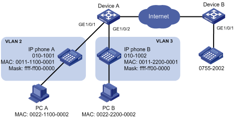
Configuration procedure
# Create VLAN 2 and VLAN 3.
<DeviceA> system-view
[DeviceA] vlan 2 to 3
Please wait... Done.
# Set the voice VLAN aging time to 30 minutes.
[DeviceA] voice vlan aging 30
# (Optional.) GigabitEthernet 1/0/1 may receive both voice traffic and data traffic at the same time. To ensure the quality of voice packets and effective bandwidth use, configure voice VLANs to operate in security mode. Configure the voice VLANs to transmit only voice packets. By default, voice VLANs operate in security mode.
[DeviceA] voice vlan security enable
# Configure the allowed OUI addresses as MAC addresses prefixed by 0011-1100-0000 or 0011-2200-0000. In this way, Device A identifies packets whose MAC addresses match any of the configured OUI addresses as voice packets.
[DeviceA] voice vlan mac-address 0011-1100-0001 mask ffff-ff00-0000 description IP phone A
[DeviceA] voice vlan mac-address 0011-2200-0001 mask ffff-ff00-0000 description IP phone B
# Configure GigabitEthernet 1/0/1 as a hybrid port.
[DeviceA] interface gigabitethernet 1/0/1
[DeviceA-GigabitEthernet1/0/1] port link-type hybrid
# (Optional.) Configure GigabitEthernet 1/0/1 to operate in automatic voice VLAN assignment mode. By default, a port operates in automatic voice VLAN assignment mode.
[DeviceA-GigabitEthernet1/0/1] voice vlan mode auto
# Configure VLAN 2 as the voice VLAN for GigabitEthernet 1/0/1.
[DeviceA-GigabitEthernet1/0/1] voice vlan 2 enable
[DeviceA-GigabitEthernet1/0/1] quit
# Configure GigabitEthernet 1/0/2.
[DeviceA] interface gigabitethernet 1/0/2
[DeviceA-GigabitEthernet1/0/2] port link-type hybrid
[DeviceA-GigabitEthernet1/0/2] voice vlan mode auto
[DeviceA-GigabitEthernet1/0/2] voice vlan 3 enable
Verifying the configuration
# Display OUI addresses, OUI address masks, and description strings.
<DeviceA> display voice vlan oui
Oui Address Mask Description
0001-e300-0000 ffff-ff00-0000 Siemens phone
0003-6b00-0000 ffff-ff00-0000 Cisco phone
0004-0d00-0000 ffff-ff00-0000 Avaya phone
0011-1100-0000 ffff-ff00-0000 IP phone A
0011-2200-0000 ffff-ff00-0000 IP phone B
0060-b900-0000 ffff-ff00-0000 Philips/NEC phone
00d0-1e00-0000 ffff-ff00-0000 Pingtel phone
00e0-7500-0000 ffff-ff00-0000 Polycom phone
00e0-bb00-0000 ffff-ff00-0000 3com phone
# Display the states of voice VLANs.
<DeviceA> display voice vlan state
Maximum of Voice VLANs: 128
Current Voice VLANs: 2
Voice VLAN security mode: Security
Voice VLAN aging time: 30 minutes
Voice VLAN enabled port and its mode:
PORT VLAN MODE COS DSCP
--------------------------------------------------------------------
GigabitEthernet1/0/1 2 AUTO 6 46
GigabitEthernet1/0/2 3 AUTO 6 46
Manual voice VLAN assignment mode configuration example
Network requirements
As shown in Figure 16, the IP phones send untagged voice traffic.
Create VLAN 2 and configure it as a voice VLAN that permits only voice traffic to pass through.
Configure GigabitEthernet 1/0/1 as a hybrid port, and configure GigabitEthernet 1/0/1 to operate in manual voice VLAN assignment mode. Configure GigabitEthernet 1/0/1 to allow voice traffic with an OUI address of 0011-2200-0000, a mask of ffff-ff00-0000, and a description string of test to be forwarded in the voice VLAN.
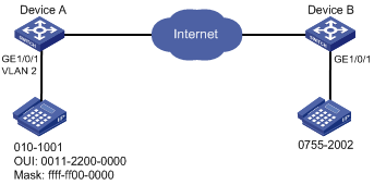
Configuration procedure
# (Optional.) Configure the voice VLAN to operate in security mode. A voice VLAN operates in security mode by default.
<DeviceA> system-view
[DeviceA] voice vlan security enable
# Add a recognizable OUI address 0011-2200-0000.
[DeviceA] voice vlan mac-address 0011-2200-0000 mask ffff-ff00-0000 description test
# Create VLAN 2.
[DeviceA] vlan 2
[DeviceA-vlan2] quit
# Configure GigabitEthernet 1/0/1 to operate in manual voice VLAN assignment mode.
[DeviceA] interface gigabitethernet 1/0/1
[DeviceA-GigabitEthernet1/0/1] undo voice vlan mode auto
# Configure GigabitEthernet 1/0/1 as a hybrid port.
[DeviceA-GigabitEthernet1/0/1] port link-type hybrid
# Configure the voice VLAN (VLAN 2) as the PVID of GigabitEthernet 1/0/1, and configure GigabitEthernet 1/0/1 to permit the voice traffic of VLAN 2 to pass through untagged.
[DeviceA-GigabitEthernet1/0/1] port hybrid pvid vlan 2
[DeviceA-GigabitEthernet1/0/1] port hybrid vlan 2 untagged
# Enable voice VLAN on GigabitEthernet 1/0/1.
[DeviceA-GigabitEthernet1/0/1] voice vlan 2 enable
Verifying the configuration
# Display OUI addresses, OUI address masks, and description strings.
<DeviceA> display voice vlan oui
Oui Address Mask Description
0001-e300-0000 ffff-ff00-0000 Siemens phone
0003-6b00-0000 ffff-ff00-0000 Cisco phone
0004-0d00-0000 ffff-ff00-0000 Avaya phone
0011-2200-0000 ffff-ff00-0000 test
00d0-1e00-0000 ffff-ff00-0000 Pingtel phone
0060-b900-0000 ffff-ff00-0000 Philips/NEC phone
00e0-7500-0000 ffff-ff00-0000 Polycom phone
00e0-bb00-0000 ffff-ff00-0000 3com phone
# Display the states of voice VLANs.
<DeviceA> display voice vlan state
Maximum of Voice VLANs: 128
Current Voice VLANs: 1
Voice VLAN security mode: Security
Voice VLAN aging time: 1440 minutes
Voice VLAN enabled port and its mode:
PORT VLAN MODE COS DSCP
--------------------------------------------------------------------
GigabitEthernet1/0/1 2 MANUAL 6 46