- Table of Contents
- Related Documents
-
| Title | Size | Download |
|---|---|---|
| 05-Interface Backup Configuration | 140.87 KB |
Interface backup configuration task list
Configuring active/standby mode
Associating an interface with a track entry
Configuring the delay timer for the backup function to take effect on system startup
Displaying and maintaining interface backup
Interface backup configuration examples
Multi-interface backup configuration example
Multi-interface load balancing configuration example
Configuring interface backup
Support for this feature depends on the device model. For more information, see About the H3C Access Controllers Configuration Guides.
Overview
Interface backup increases network reliability. The active interface transmits services, and the standby interfaces are in the backup state. When the active interface fails or the link fails, or when the traffic on the active interface exceeds the configured threshold, a standby interface is activated to transmit services.
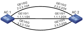
As shown in Figure 1, interfaces GigabitEthernet 1/0/1, GigabitEthernet 1/0/2, and GigabitEthernet 1/0/3 on AC 1 back up each other. GigabitEthernet 1/0/1 transmits data, and GigabitEthernet 1/0/2 and GigabitEthernet 1/0/3 are standby interfaces that have different priorities.
Figure 1 Diagram for interface backup
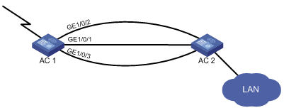
When interface GigabitEthernet 1/0/1 or its link to AC 2 fails, or when the traffic on GigabitEthernet 1/0/1 exceeds the configured threshold, the standby interface with the highest priority is activated, ensuring uninterrupted data transmission.
Active and standby interfaces
In interface backup, an interface can be an active interface or standby interface. Layer 3 Ethernet interfaces and Layer 3 Ethernet subinterfaces can serve as active or standby interfaces.
· Active interface—An active interface transmits data, and can be configured with up to three standby interfaces (for example, GigabitEthernet 1/0/1 in Figure 1).
· Standby interface—Standby interfaces function as backups for active interfaces (for example, interfaces GigabitEthernet 1/0/2 and GigabitEthernet 1/0/3 in Figure 1), which are generally idle. One standby interface can only back up one active interface.
How interface backup works
Interface backup operates in active/standby mode or in load balancing mode.
Active/standby mode
As shown in Figure 2, interface GigabitEthernet 1/0/1 on AC 1 acts as the active interface and interfaces GigabitEthernet 1/0/2 and GigabitEthernet 1/0/3 act as the standby interfaces.
Figure 2 Diagram for active/standby mode
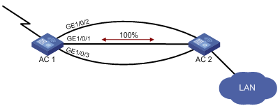
In active/standby mode, only one interface transmits data at any given time.
· When the active interface is operating properly, even if the traffic is overloaded, the standby interface is in a backup state. All traffic is transmitted by the active interface.
· If the active interface fails, the standby interface with highest priority takes over to transmit data.
· When the active interface is restored, it resumes data transmission.
Load balancing mode
As shown in Figure 3, interface GigabitEthernet 1/0/1 on AC 1 acts as the active interface, and interfaces GigabitEthernet 1/0/2 and GigabitEthernet 1/0/3 act as the standby interfaces.
Figure 3 Diagram for load balancing mode
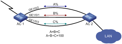
In load balancing mode, you can set an upper threshold (enable-threshold) and a lower threshold (disable-threshold). Traffic can be shared among multiple interfaces:
· When the traffic on the active interface exceeds the predefined enable-threshold, the highest priority standby interface is activated. Other standby interfaces are activated in descending priority order if exceeding traffic still exists.
· When the traffic on the active interface decreases below the predefined disable-threshold, the system shuts down the lowest priority standby interface first and then shuts down the other standby interfaces in ascending priority order depending on traffic size.
Interface backup configuration task list
|
Task |
Remarks |
|
|
Optional |
||
|
Optional |
||
|
Configuring the delay timer for the backup function to take effect on system startup |
Optional |
|
Configuring interface backup
You can configure interface backup through active/standby mode or association between an interface and a track entry, but you cannot configure them at the same time.
Configuring active/standby mode
You can configure multiple standby interfaces for one active interface. The standby interfaces are activated depending on their priority, with the highest priority being activated first.
To prevent frequent interface switchover as a result of interface instability, you can configure a switchover delay. A standby interface then takes over only if the active interface remains down upon expiry of the delay.
Follow these guidelines when you configure active/standby mode:
· To configure multiple standby interfaces for an active interface, execute the standby interface command repeatedly.
· You can use the ip route-static command in system view to configure the routes for reaching a destination network through the active interface and its standby interfaces. For more information about the command, see Layer 3—IP Routing Command Reference.
· If multiple standby interfaces have the same priority, when the active interface is down, the standby interface configured first is selected.
To configure active/standby mode:
|
Step |
Command |
Remarks |
|
1. Enter system view. |
system-view |
N/A |
|
2. Enter interface view. |
interface interface-type interface-number |
N/A |
|
3. Specify a standby interface for the active interface. |
standby interface interface-type interface-number [ priority ] |
By default, no standby interface is specified for the active interface. |
|
4. Set switchover delays. |
standby timer delay enable-delay disable-delay |
Optional. Both thresholds are 0 by default, indicating immediate switchover without delay. |
Associating an interface with a track entry
You can associate a standby interface with a track entry to enable the interface to monitor the state of the active interface through the track entry and change the backup state of the interface accordingly.
· If the state of the track entry is positive, the link connecting the active interface is normal and the standby interface stays in the backup state.
· If the state of the track entry is negative, the link connecting the active interface is not functioning normally. The standby interface becomes the active interface to transmit data.
· When you associate an interface with a track entry, if the track entry is invalid, the interface keeps its forwarding state. After your configuration, if the state of the track entry changes to invalid, the standby interface will become the active interface.
Follow these guidelines when you associate an interface with a track entry:
· One interface can be associated with one track entry only. If you repeatedly execute the standby track command, the latter configuration overwrites the previous one.
· The track entry associated with an interface can be one you have not created yet. After you create a track entry with the track command, the association takes effect.
· For more information about the track module, see High Availability Configuration Guide.
To associate an interface with a track entry:
|
Step |
Command |
Remarks |
|
1. Enter system view. |
system-view |
N/A |
|
2. Enter interface view. |
interface interface-type interface-number |
N/A |
|
3. Associate an interface with a track entry. |
standby track track-entry-number |
By default, an interface is not associated with a track entry. |
Configuring load balancing
Interface backup detects the data traffic on the active interface to determine whether to bring up or shut down the standby interface.
When multiple standby interfaces are assigned the same priority, they are brought up or shut down depending on the order they are configured:
· The standby interface configured first is used first to participate in load balancing with the active interface.
· The standby interface configured later is shut down first and exits load balancing with the active interface.
To configure load balancing:
|
Step |
Command |
Remarks |
|
1. Enter system view. |
system-view |
N/A |
|
2. Enter active interface view. |
interface interface-type interface-number |
N/A |
|
3. Configure the available bandwidth used for setting the thresholds. |
standby bandwidth size |
Optional. 0 kbps by default. |
|
4. Configure load balancing thresholds. |
standby threshold enable-threshold disable-threshold |
No load balancing thresholds are configured by default. |
|
5. Configure the interval for detecting traffic size on the active interface. |
standby timer flow-check interval |
Optional. 30 seconds by default. |
Configuring the delay timer for the backup function to take effect on system startup
Generally, H3C recommends using the default settings for the devices supporting this feature. If you set a too short timer, the standby interfaces will be activated and deactivated in a short time on system startup; if you set a too long timer, when the active interface fails, the standby interfaces take too long time to take effect on system startup.
This feature takes effect on all the standby interfaces working in active/standby mode, but does not take effect on the standby interfaces working in load balancing mode.
The device restores its configuration when starting up. If the device is configured with the backup function, during the configuration restoration process, the system enables the delay timer for the backup function to take effect on system startup, because the status of all the interfaces is down. If the delay timer times out, but the active interface is not up (because the cables are not well connected, or parameter negotiation is being performed), the system will activate a standby interface to start interface backup. When the active interface is up, the system will disable the standby interface, and set its status to down. To avoid activation and deactivation (up and down) of the standby interfaces in a short time on system startup, you can modify the delay timer for the backup function to take effect on system startup, so that the standby interfaces will be activated only when the delay timer times out and the active interface is not up.
To set the delay timer for the backup function to take effect on system startup:
|
Step |
Command |
Remarks |
|
1. Enter system view. |
system-view |
N/A |
|
2. Set the delay timer for the backup function to take effect on system startup. |
standby timer startup seconds |
Optional. 30 seconds by default. |
Displaying and maintaining interface backup
|
Task |
Command |
Remarks |
|
Display statistics about the traffic on the active interfaces enabled with load balancing. |
display standby flow [ | { begin | exclude | include } regular-expression ] |
Available in any view. |
|
Display the state information of the active and standby interfaces. |
display standby state [ | { begin | exclude | include } regular-expression ] |
Available in any view. |
Interface backup configuration examples
Multi-interface backup configuration example
Network requirements
Use interfaces GigabitEthernet 1/0/2 and GigabitEthernet 1/0/3 on AC 1 to back up the active interface GigabitEthernet 1/0/1, assigning interface GigabitEthernet 1/0/2 a higher priority, and configure switchover delays.
Configuration procedure
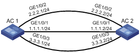
1. Configure IP addresses:
Follow Figure 4 to configure the IP address and subnet mask for each interface. (Details not shown.)
2. Configure the standby interfaces and switch delays on AC 1:
# Specify interfaces GigabitEthernet 1/0/2 and GigabitEthernet 1/0/3 on AC 1 to back up GigabitEthernet 1/0/1, and assign them the priorities 30 and 20, respectively.
[AC1] interface gigabitethernet 1/0/1
[AC1-GigabitEthernet1/0/1] standby interface gigabitethernet 1/0/2 30
[AC1-GigabitEthernet1/0/1] standby interface gigabitethernet 1/0/3 20
# Configure switchover delays to 10 seconds.
[AC1-GigabitEthernet1/0/1] standby timer delay 10 10
3. Verify the configuration on AC 1:
# Display the state of the active and standby interfaces.
[AC1-GigabitEthernet1/0/1] display standby state
Interface Interfacestate Standbystate Standbyflag Pri Loadstate
GigabitEthernet1/0/1 UP MUP MU
GigabitEthernet1/0/2 STANDBY STANDBY BU 30
GigabitEthernet1/0/3 STANDBY STANDBY BU 20
Backup-flag meaning:
M---MAIN B---BACKUP V---MOVED U---USED
D---LOAD P---PULLED
# Manually shut down the active interface GigabitEthernet 1/0/1.
[AC1-GigabitEthernet1/0/1] shutdown
# 10 seconds after the active interface was shut down, standby interface GigabitEthernet 1/0/2 with a higher priority is enabled. Then you can view the state of the active and standby interfaces.
[AC1-GigabitEthernet1/0/1] display standby state
Interface Interfacestate Standbystate Standbyflag Pri Loadstate
GigabitEthernet1/0/1 DOWN MDOWN MU
GigabitEthernet1/0/2 UP UP BU 30
GigabitEthernet1/0/3 STANDBY STANDBY BU 20
Backup-flag meaning:
M---MAIN B---BACKUP V---MOVED U---USED
D---LOAD P---PULLED
Multi-interface load balancing configuration example
Network requirement
Use interfaces GigabitEthernet 1/0/2 and GigabitEthernet 1/0/3 on AC 1 to back up the active interface GigabitEthernet 1/0/1, assigning interface GigabitEthernet 1/0/2 a higher priority.
Configure the available bandwidth used for setting the thresholds and the enable-threshold and disable-threshold of load balancing.
Configuration procedure
1. Configure IP addresses:
Follow Figure 5 to configure the IP address and subnet mask for each interface. (Details not shown.)
2. Configure the standby interfaces and load balancing on AC 1:
# Specify interfaces GigabitEthernet 1/0/2 and GigabitEthernet 1/0/3 on AC 1 to back up GigabitEthernet 1/0/1, and assign them the priorities 30 and 20, respectively.
[AC1] interface gigabitethernet 1/0/1
[AC1-GigabitEthernet1/0/1] standby interface gigabitethernet 1/0/2 30
[AC1-GigabitEthernet1/0/1] standby interface gigabitethernet 1/0/3 20
# Configure the available bandwidth used for setting the thresholds to 10000 kbps.
[AC1-GigabitEthernet1/0/1] standby bandwidth 10000
# Configure the enable-threshold of load balancing to 80 and the disable-threshold to 20.
[AC1-GigabitEthernet1/0/1] standby threshold 80 20
3. Verify the configuration on AC 1:
# Display the traffic statistics for the active interface taking part in load balancing.
[AC1-GigabitEthernet1/0/1] display standby flow
Interfacename : GigabitEthernet1/0/1
Flow-interval(s) : 30
LastInOctets : 139
LastOutOctets : 22033
InFlow(Octets) : 0
OutFlow(Octets) : 0
BandWidth(b/s) : 10000
UsedBandWidth(b/s) : 0
# Display the state of the active and standby interfaces.
[AC1-GigabitEthernet1/0/1] display standby state
Interface Interfacestate Standbystate Standbyflag Pri Loadstate
GigabitEthernet1/0/1 UP MUP MUD TO-HYPNOTIZE
GigabitEthernet1/0/2 STANDBY STANDBY BU 30
GigabitEthernet1/0/3 STANDBY STANDBY BU 20
Backup-flag meaning:
M---MAIN B---BACKUP V---MOVED U---USED
D---LOAD P---PULLED
# When the data traffic on the active interface GigabitEthernet 1/0/1 exceeds 8000 kbps (that is, 10000 kbps × 80%), standby interface GigabitEthernet 1/0/2 with a higher priority is enabled first. Then you can view the state of the active and standby interfaces.
[AC1-GigabitEthernet1/0/1] display standby state
Interface Interfacestate Standbystate Standbyflag Pri Loadstate
GigabitEthernet1/0/1 UP MUP MUD
GigabitEthernet1/0/2 UP UP BU 30
GigabitEthernet1/0/3 STANDBY STANDBY BU 20
Backup-flag meaning:
M---MAIN B---BACKUP V---MOVED U---USED
D---LOAD P---PULLED