- Table of Contents
- Related Documents
-
| Title | Size | Download |
|---|---|---|
| 03-Stateful Failover Configuration | 83.27 KB |
Stateful failover configuration task list
Displaying and maintaining stateful failover
Stateful failover configuration example
Configuring stateful failover
Support for this feature depends on the device model. For more information, see About the H3C Access Controllers Configuration Guides.
Stateful failover overview
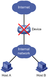
Some customers require the key entries or access points of their networks, such as the Internet access point of an enterprise or a database server of a bank, to be highly reliable to ensure continuous data transmission. Deploying only one device (even with high reliability) in such a network risks a single point of failure, as shown in Figure 1. Stateful failover can solve this problem.
Figure 1 Network with one device deployed
Operating procedure
Stateful failover involves service backup and traffic switchover. Stateful failover works as follows:
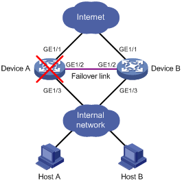
1. As shown in Figure 2, Device A and Device B connect to each other over a failover link.
2. The two devices exchange state negotiation messages periodically through the failover link. After the two devices enter the synchronized state, they back up the sessions of each other to make sure that the sessions on them are consistent.
3. If one device fails, the other device can take over the services by using VRRP to avoid service interruption.
In this document, the stateful failover feature supports backing up portal, 802.1X, and DHCP services.
Figure 2 Network diagram for stateful failover
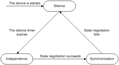
Stateful failover states
Stateful failover includes the following states:
· Silence—The device has just started, or is transiting from synchronization state to independence state.
· Independence—The silence timer has expired, but no failover link is established.
· Synchronization—The device has completed state negotiation with the other device and is ready for service backup.
Figure 3 Stateful failover state relations
Stateful failover configuration task list
To implement stateful failover on two devices, you need to perform the following tasks:
· Routing configuration. Configure VRRP on the devices and the uplink/downlink devices to ensure that the traffic can automatically switch to the other device when a device fails.
· Service backup configuration. It can implement real-time service backup between the two devices.
This configuration guide only introduces the service backup configuration.
Complete the following tasks to configure stateful failover:
|
Task |
Remarks |
|
Required. |
|
|
Required. |
|
|
Service module related configurations |
Optional. For a device providing portal services, you need to perform further configurations on the device before it can automatically back up portal service information to the backup device. For more information, see Security Configuration Guide. |
Enabling stateful failover
When you enable stateful failover with the dhbk enable backup-type { dissymmetric-path | symmetric-path } command, one of the following happens:
· If you specify the dissymmetric-path keyword, the two devices operate in active/active mode. Sessions enter and leave the internal network through different devices to achieve load sharing.
· If you specify the symmetric-path keyword, the two devices operate in active/standby mode. Sessions enter and leave the internal network through one device.
Select a keyword based on the network environment and resources and specify the same keyword for both devices.
To enable stateful failover:
|
Step |
Command |
Remarks |
|
1. Enter system view. |
system-view |
N/A |
|
2. Enable stateful failover in a specified mode. |
dhbk enable backup-type { dissymmetric-path | symmetric-path } |
Disabled by default. |
Configuring the backup VLAN
After you specify a VLAN as a backup VLAN, the interfaces added to the VLAN can serve as stateful failover interfaces to transmit stateful failover packets.
The device identifies stateful failover packets by the VLAN tag and private protocol number, and broadcasts them in the backup VLAN to the peer. Do not configure other services for the backup VLAN (such as MAC VLAN or Voice VLAN). Otherwise, the operation of stateful failover may be affected.
The interfaces assigned to a backup VLAN can forward other types of packets in addition to stateful failover packets.
To configure a backup VLAN:
|
Step |
Command |
Remarks |
|
1. Enter system view. |
system-view |
N/A |
|
2. Create a VLAN and assign interfaces to the VLAN. |
See Layer 2 Configuration Guide. |
N/A |
|
3. Return to system view. |
quit |
N/A |
|
4. Specify the VLAN as a backup VLAN. |
dhbk vlan vlan-id |
Not specified by default. |
Displaying and maintaining stateful failover
|
Task |
Command |
Remarks |
|
Display the running status and related information of stateful failover. |
display dhbk status [ | { begin | exclude | include } regular-expression ] |
Available in any view. |
Stateful failover configuration example
For more information about the portal security stateful failover configuration example, see Security Configuration Guide.
Configuration guidelines
When you configure stateful failover, follow these guidelines:
· Stateful failover can be implemented only between two devices.
· The same numbered interfaces must exist on the two devices. Otherwise, session backup fails. For example, if Device A uses GigabitEthernet 1/0/1 and GigabitEthernet 1/0/2 to forward backup data, Device B must also use GigabitEthernet 1/0/1 and GigabitEthernet 1/0/2.