- Table of Contents
- Related Documents
-
| Title | Size | Download |
|---|---|---|
| 03-Multicast VLAN Configuration | 246.36 KB |
Port-based multicast VLAN configuration task list
Configuring user port attributes
Configuring multicast VLAN ports
Adding user ports to the multicast VLAN
Specifying the multicast VLAN on the user ports
Displaying and maintaining a multicast VLAN
Multicast VLAN configuration examples
Port-based multicast VLAN configuration example (for the WX6000 series)
Port-based multicast VLAN configuration example (for the WX5540E)
Port-based multicast VLAN configuration example (for the WX3000E series)
Configuring multicast VLANs
Overview
Figure 1 shows the traditional multicast programs-on-demand mode. When the hosts (Host A, Host B, and Host C) that belong to different VLANs require the multicast programs-on-demand service, the Layer 3 device (Router A) must forward a separate copy of the multicast data in each VLAN to the Layer 2 device (AC). This causes a waste of network bandwidth and adds an extra burden on the Layer 3 device.
Figure 1 Multicast transmission without the multicast VLAN feature
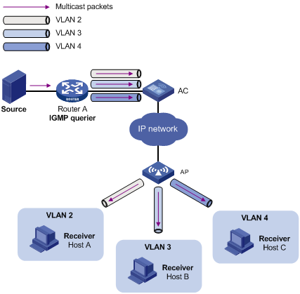
The multicast VLAN feature on the Layer 2 device is the solution to this issue. After the multicast VLAN is configured on the Layer 2 device, the Layer 3 device only replicates the multicast data in the multicast VLAN instead of making a separate copy in each VLAN. This saves network bandwidth and lessens the burden on the Layer 3 device.
The multicast VLAN feature can be implemented in a port-based multicast VLAN.
As shown in Figure 2, Host A, Host B, and Host C are in VLAN 2 through VLAN 4, respectively. All the user ports (ports with attached hosts) on AC are hybrid ports. On AC, VLAN 10 is configured as a multicast VLAN, all the user ports are assigned to VLAN 10, and IGMP snooping is enabled for the multicast VLAN and VLAN 2 through VLAN 4.
Figure 2 Port-based multicast VLAN
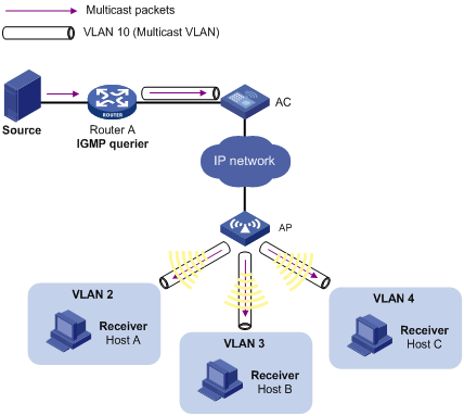
After the configuration, if AC receives an IGMP message on a user port, it tags the message with the multicast VLAN ID and relays it to the IGMP querier. This allows IGMP snooping to uniformly manage the router ports and member ports in the multicast VLAN. When Router A forwards multicast data to AC, it sends only one copy of the multicast data to AC. AC distributes the data to all member ports in the multicast VLAN.
Port-based multicast VLAN configuration task list
|
Task |
Remarks |
|
Use either method. |
|
Configuration guidelines
· A user port can be configured as a multicast VLAN port only if it is an Ethernet port, a WLAN-ESS interface, or a Layer 2 aggregate interface.
· In Ethernet interface view, WLAN-ESS interface view, or Layer 2 aggregate interface view, the configurations are effective only on the current port. In port group view, the configurations are effective on all ports in the current port group.
Configuration prerequisites
Before you configure a port-based multicast VLAN, complete the following tasks:
· Create VLANs as required.
· Enable IGMP snooping for the VLAN to be configured as a multicast VLAN.
· Enable IGMP snooping for all the VLANs that contain multicast data receivers.
Configuring user port attributes
First, configure a user port as a hybrid port that permits VLAN-tagged packets to pass, and configure the user VLAN to which the user ports belong as the PVID.
Then, configure the user port to permit the multicast VLAN packets to pass and to untag the packets. After receiving the multicast VLAN-tagged packets from the upstream device, the Layer 2 device untags the multicast packets and forwards them to its downstream device.
To configure user port attributes:
|
Step |
Command |
Remarks |
|
1. Enter system view. |
system-view |
N/A |
|
2. Enter Ethernet interface view or port group view. |
· Enter Ethernet interface view: · Enter port group view: |
Use either command. |
|
3. Configure the user port link type as hybrid. |
port link-type hybrid |
By default, the port link type is access. |
|
4. Specify the PVID of the hybrid port. |
port hybrid pvid vlan vlan-id |
By default, the PVID of a hybrid port is VLAN 1. |
|
5. Configure the current user port to permit multicast VLAN packets to pass. |
port hybrid vlan vlan-id-list { tagged | untagged } |
By default, a hybrid port permits only packets of VLAN 1 to pass. |
For more information about the port link-type, port hybrid pvid vlan, and port hybrid vlan commands, see Layer 2—LAN Switching Command Reference.
Configuring multicast VLAN ports
When you configure multicast VLAN ports, follow these guidelines:
· Do not configure a multicast VLAN on a device with multicast routing enabled.
· The VLAN to be configured as a multicast VLAN must exist.
· A port cannot belong to multiple multicast VLANs.
Adding user ports to the multicast VLAN
|
Step |
Command |
Remarks |
|
1. Enter system view. |
system-view |
N/A |
|
2. Configure the specified VLAN as a multicast VLAN. |
multicast-vlan vlan-id |
By default, a VLAN is not a multicast VLAN. |
|
3. Assign ports to the multicast VLAN. |
port interface-list |
By default, a multicast VLAN has no ports. |
Specifying the multicast VLAN on the user ports
|
Step |
Command |
Remarks |
|
1. Enter system view. |
system-view |
N/A |
|
2. Configure the specified VLAN as a multicast VLAN. |
multicast-vlan vlan-id |
A VLAN is not a multicast VLAN by default. |
|
3. Return to system view. |
quit |
N/A |
|
4. Enter interface view or port group view. |
· Enter interface view: · Enter port group view: |
Use either command. |
|
5. Assign the current port to the multicast VLAN. |
port multicast-vlan vlan-id |
By default, a user port does not belong to any multicast VLAN. |
Displaying and maintaining a multicast VLAN
|
Task |
Command |
Remarks |
|
Display information about a multicast VLAN. |
display multicast-vlan [ vlan-id ] [ | { begin | exclude | include } regular-expression ] |
Available in any view. |
Multicast VLAN configuration examples
Port-based multicast VLAN configuration example (for the WX5000 series/WX3500E series/WX5510E/WX2540E/WAC360 series)
Network requirements
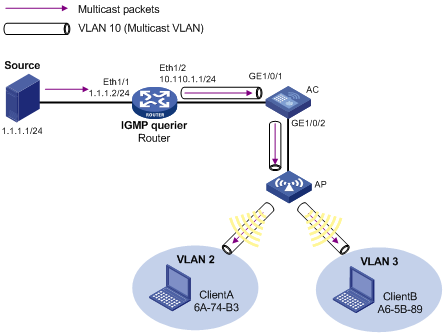
As shown in Figure 3, IGMPv2 is running between Router and AC. IGMPv2 snooping is running on AC. Router acts as the IGMP querier.
Create VLAN 10 on AC, assign GigabitEthernet 1/0/1 to VLAN 10, and enable IGMP snooping in the VLAN. Create WLAN-ESS 1 on AC and configure it as a hybrid port with VLAN 10 as the PVID. Configure the port to allow packets from VLAN 2, VLAN 3, and VLAN 10 to pass. Configure the MAC-based VLAN feature so that Client A and Client B belong to VLAN 2 and VLAN 3 respectively.
Create VLAN 2, VLAN 3, and VLAN 10 on Switch, and enable IGMP snooping in these VLANs. Configure Ethernet 1/1 and Ethernet 1/3 as trunk ports, and configure them to allow packets of VLAN 2, VLAN 3, and VLAN 10 to pass.
The multicast source sends multicast data to multicast group 224.1.1.1. Client A and Client B are receivers of this multicast group.
Configure the port-based multicast VLAN feature so that Router just sends multicast data to AC through the multicast VLAN and AC forwards the multicast data to the receivers that belong to different user VLANs.

Configuration procedure
1. Configure the IP address and subnet mask for each interface, as shown in Figure 3. (Details not shown.)
2. On Router, enable IP multicast routing, enable PIM-DM on each interface, and enable IGMP on the host-side interface Ethernet 1/2.
<Router> system-view
[Router] multicast routing-enable
[Router] interface ethernet 1/1
[Router-Ethernet1/1] pim dm
[Router-Ethernet1/1] quit
[Router] interface ethernet 1/2
[Router-Ethernet1/2] pim dm
[Router-Ethernet1/2] igmp enable
[Router-Ethernet1/2] quit
3. Configure the AC:
# Enable IGMP snooping globally.
<AC> system-view
[AC] igmp-snooping
[AC-igmp-snooping] quit
# Create VLAN 10, assign GigabitEthernet 1/0/1 to VLAN 10, and enable IGMP snooping in this VLAN.
[AC] vlan 10
[AC-vlan10] port GigabitEthernet1/0/1
[AC-vlan10] igmp-snooping enable
[AC-vlan10] quit
# Configure GigabitEthernet 1/0/2 as a trunk port, and configure it to allow packets from VLAN 2, VLAN 3, and VLAN 10 to pass.
[AC] interface GigabitEthernet 1/0/2
[AC-GigabitEthernet1/0/2] port link-type trunk
[AC-GigabitEthernet1/0/2] port trunk permit vlan 2 3 10
[AC-GigabitEthernet1/0/2] quit
# Create VLAN 2 and VLAN 3.
[AC] vlan 2
[AC-vlan2] vlan 3
[AC-vlan3] quit
# Create WLAN-ESS 1, configure it as a hybrid port, and configure VLAN 10 as the PVID.
[AC] interface WLAN-ESS 1
[AC-WLAN-ESS1] port link-type hybrid
[AC-WLAN-ESS1] port hybrid pvid vlan 10
# Assign WLAN-ESS 1 to VLAN 2, VLAN 3, and VLAN 10, and configure it to send packets from these VLANs without tags.
[AC-WLAN-ESS1] port hybrid vlan 2 3 10 untagged
# Enable the MAC-based VLAN feature on WLAN-ESS 1.
[AC-WLAN-ESS1] mac-vlan enable
# Associate the MAC addresses 6A-74-B3 and A6-5B-89 with VLAN 2 and VLAN 3, respectively so that Client A and Client B belong to VLAN 2 and VLAN 3, respectively.
[AC] mac-vlan mac-address 6A-74-B3 vlan 2
[AC] mac-vlan mac-address A6-5B-89 vlan 3
# Enable IGMP snooping in VLAN 2 and VLAN 3.
[AC] vlan 2
[AC-vlan2] igmp-snooping enable
[AC-vlan2] quit
[AC] vlan 3
[AC-vlan3] igmp-snooping enable
[AC-vlan3] quit
# Configure VLAN 10 as a multicast VLAN.
[AC] multicast-vlan 10
# Assign WLAN-ESS 1 to VLAN 10.
[AC-mvlan-10] port WLAN-ESS 1
[AC-mvlan-10] quit
4. Configure Switch:
# Enable IGMP snooping globally.
<Switch> system-view
[Switch] igmp-snooping
[Switch-igmp-snooping] quit
# Create VLAN 10, VLAN 2, and VLAN 3, and enable IGMP snooping in these VLANs.
[Switch] vlan 10
[Switch-vlan10] igmp-snooping enable
[Switch-vlan10] vlan 2
[Switch-vlan2] igmp-snooping enable
[Switch-vlan2] vlan 3
[Switch-vlan3] igmp-snooping enable
[Switch-vlan3] quit
# Configure Ethernet 1/1 and Ethernet 1/2 as trunk ports, and configure them to permit packets from VLAN 2, VLAN 3, and VLAN 10 to pass.
[Switch] interface ethernet 1/1
[Switch-Ethernet1/1] port link-type trunk
[Switch-Ethernet1/1] port trunk permit vlan 2 3 10
[Switch-Ethernet1/1] quit
[Switch] interface ethernet 1/2
[Switch-Ethernet1/2] port link-type trunk
[Switch-Ethernet1/2] port trunk permit vlan 2 3 10
[Switch-Ethernet1/2] quit
Verifying the configuration
# Display the multicast VLAN information on the AC.
[AC] display multicast-vlan
Total 1 multicast-vlan(s)
Multicast vlan 10
port list:
WLAN-ESS 1
# Display the IGMP snooping multicast group information on the AC.
[AC] display igmp-snooping group
Total 1 IP Group(s).
Total 1 IP Source(s).
Total 1 MAC Group(s).
Port flags: D-Dynamic port, S-Static port, A-Aggregation port, C-Copy port
Subvlan flags: R-Real VLAN, C-Copy VLAN
Vlan(id):10.
Total 1 IP Group(s).
Total 1 IP Source(s).
Total 1 MAC Group(s).
Router port(s):total 1 port.
GE1/0/1 (D)
IP group(s):the following ip group(s) match to one mac group.
IP group address:224.1.1.1
(0.0.0.0, 224.1.1.1):
Host port(s):total 1 port.
WLAN-DBSS1:1 (D)
MAC group(s):
MAC group address:0100-5e01-0101
Host port(s):total 1 port.
WLAN-DBSS 1:1
The output shows that IGMP snooping is maintaining the router ports and member ports in VLAN 10.
Port-based multicast VLAN configuration example (for the WX6000 series)
Network requirements
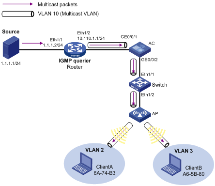
As shown in Figure 4, create VLAN 10 on AC, assign GigabitEthernet 0/0/1 to VLAN 10, and enable IGMP snooping in the VLAN. Configure Ten-Gigabitethernet 2/0/1 as a trunk port on AC, and configure it to permit packets of VLAN 2, VLAN 3, and VLAN 10 to pass. IGMPv2 is running between Router and AC, and IGMPv2 snooping is running on AC, with Router acting as the IGMP querier.
Create WLAN-ESS 1 on AC and configure it as a hybrid port with VLAN 10 as the PVID. Configure the port to permit packets from VLAN 2, VLAN 3, and VLAN 10 to pass. Configure the MAC-based VLAN feature so that Client A and Client B belong to VLAN 2 and VLAN 3, respectively.
Create VLAN 2, VLAN 3, and VLAN 10 on Switch, and enable IGMP snooping in these VLANs. Configure Ethernet 1/1 and Ethernet 1/3 as trunk ports, and configure them to allow packets of VLAN 2, VLAN 3, and VLAN 10 to pass.
The multicast source sends multicast data to multicast group 224.1.1.1. Client A and Client B are receivers of this multicast group.
Configure the port-based multicast VLAN feature so that Router can send multicast data to the receivers connecting with the AC through the multicast VLAN.
Configuration procedure
1. Configure the IP address and subnet mask for each interface, as shown in Figure 4. (Details not shown.)
2. On Router, enable IP multicast routing, enable PIM-DM on each interface, and enable IGMP on the AC-side interface Ethernet 1/2.
<Router> system-view
[Router] multicast routing-enable
[Router] interface ethernet 1/1
[Router-Ethernet1/1] pim dm
[Router-Ethernet1/1] quit
[Router] interface ethernet 1/2
[Router-Ethernet1/2] pim dm
[Router-Ethernet1/2] igmp enable
[Router-Ethernet1/2]quit
3. Configure the AC (for the WX6103):
# On the configuration interface of the WX6103 AC main control board, enable IGMP snooping globally.
<AC> system-view
[AC] igmp-snooping
[AC-igmp-snooping] quit
# Create VLAN 10, and enable IGMP snooping in this VLAN.
[AC] vlan 10
[AC-vlan10] igmp-snooping enable
[AC-vlan10] quit
# Configure Ten-Gigabitethernet 2/0/1 as a trunk port, and configure it to allow packets from VLAN 2, VLAN 3, and VLAN 10 to pass.
[AC] interface Ten-GigabitEthernet 2/0/1
[AC-Ten-GigabitEthernet2/0/1] port link-type trunk
[AC-Ten-GigabitEthernet2/0/1] port trunk permit vlan 2 3 10
[AC-Ten-GigabitEthernet2/0/1] quit
# Log in to the configuration interface of the switching interface board from the WX6103 main control board by using the oap command, and enable IGMP snooping globally. Create VLAN 10, assign GigabitEthernet 0/0/1 to this VLAN, and enable IGMP snooping in this VLAN.
<Device> system-view
[Device] igmp-snooping
[Device] vlan 10
[Device-vlan10] port GigabitEthernet 0/0/1
[Device-vlan10] igmp-snooping enable
[Device-vlan10] quit
# Configure GigabitEthernet 0/0/2 as a trunk port, and configure it to allow packets from VLAN 2, VLAN 3, and VLAN 10 to pass.
[Device] interface GigabitEthernet 0/0/2
[Device-GigabitEthernet0/0/2] port link-type trunk
[Device-GigabitEthernet0/0/2] port trunk permit vlan 2 3 10
[Device-GigabitEthernet0/0/2] quit
# Use Ctrl + K to return to the configuration interface of the main control board.
# Create VLAN 2 and VLAN 3.
[AC] vlan 2
[AC-vlan2] vlan 3
[AC-vlan3] quit
# Create WLAN-ESS 1, configure it as a hybrid port, and configure VLAN 10 as the PVID.
[AC] interface WLAN-ESS 1
[AC-WLAN-ESS1] port link-type hybrid
[AC-WLAN-ESS1] port hybrid pvid vlan 10
# Assign WLAN-ESS 1 to VLAN 2, VLAN 3, and VLAN 10, and configure it to send packets from these VLANs without tags.
[AC-WLAN-ESS1] port hybrid vlan 2 3 10 untagged
# Enable the MAC-based VLAN feature on WLAN-ESS 1.
[AC-WLAN-ESS1] mac-vlan enable
# Associate the MAC addresses 6A-74-B3 and A6-5B-89 with VLAN 2 and VLAN 3, respectively so that Client A and Client B belong to VLAN 2 and VLAN 3, respectively.
[AC] mac-vlan mac-address 6A-74-B3 vlan 2
[AC] mac-vlan mac-address A6-5B-89 vlan 3
# Enable IGMP snooping in VLAN 2 and VLAN 3.
[AC] vlan 2
[AC-vlan2] igmp-snooping enable
[AC-vlan2] quit
[AC] vlan 3
[AC-vlan3] igmp-snooping enable
[AC-vlan3] quit
# Configure VLAN 10 as a multicast VLAN.
[AC] multicast-vlan 10
# Assign WLAN-ESS 1 to VLAN 10.
[AC-mvlan-10] port WLAN-ESS 1
[AC-mvlan-10] quit
4. Configure the AC (for the WX6000 series AC module)
# Enable IGMP snooping globally on the configuration interface of the switch that is installed with the WX6000 series AC module.
<Device> system-view
[Device] igmp-snooping
[Device-igmp-snooping] quit
# Create VLAN 10, assign GigabitEthernet 0/0/1 to VLAN 10, and enable IGMP snooping in this VLAN.
[Device] vlan 10
[Device-vlan10] port GigabitEthernet 0/0/1
[Device-vlan10] igmp-snooping enable
[Device-vlan10] quit
# Configure GigabitEthernet 0/0/2 as a trunk port, and configure it to allow packets from VLAN 2, VLAN 3, and VLAN 10 to pass.
[Device] interface GigabitEthernet 0/0/2
[Device-GigabitEthernet0/0/2] port link-type trunk
[Device-GigabitEthernet0/0/2] port trunk permit vlan 2 3 10
[Device-GigabitEthernet0/0/2] quit
# Log in to the configuration interface of the WX6000 series AC module on the switch using the oap command, and enable IGMP snooping globally. Create VLAN 10, and enable IGMP snooping in this VLAN.
<Device> oap connect slot 2
Press CTRL+K to quit.
Connected to OAP!
User interface aux0 is available.
Press ENTER to get started.
<AC> system-view
[AC] igmp-snooping
[AC] vlan 10
[AC-vlan10] igmp-snooping enable
[AC-vlan10] quit
# Configure Ten-GigabitEthernet 2/0/1 as a trunk port, and configure it to allow packets from VLAN 2, VLAN 3, and VLAN 10 to pass.
[AC] interface Ten-GigabitEthernet 2/0/1
[AC-Ten-GigabitEthernet2/0/1] port link-type trunk
[AC-Ten-GigabitEthernet2/0/1] port trunk permit vlan 2 3 10
[AC-Ten-GigabitEthernet2/0/1] quit
# Create VLAN 2 and VLAN 3.
[AC] vlan 2
[AC-vlan2] vlan 3
[AC-vlan3] quit
# Create WLAN-ESS 1, configure it as a hybrid port, and configure VLAN 10 as the PVID.
[AC] interface WLAN-ESS 1
[AC-WLAN-ESS1] port link-type hybrid
[AC-WLAN-ESS1] port hybrid pvid vlan 10
# Assign WLAN-ESS 1 to VLAN 2, VLAN 3, and VLAN 10, and configure it to send packets from these VLANs without tags.
[AC-WLAN-ESS1] port hybrid vlan 2 3 10 untagged
# Enable the MAC-based VLAN feature on WLAN-ESS 1.
[AC-WLAN-ESS1] mac-vlan enable
# Associate the MAC addresses 6A-74-B3 and A6-5B-89 with VLAN 2 and VLAN 3, respectively so that Client A and Client B belong to VLAN 2 and VLAN 3, respectively.
[AC] mac-vlan mac-address 6A-74-B3 vlan 2
[AC] mac-vlan mac-address A6-5B-89 vlan 3
# Enable IGMP snooping in VLAN 2 and VLAN 3.
[AC] vlan 2
[AC-vlan2] igmp-snooping enable
[AC-vlan2] quit
[AC] vlan 3
[AC-vlan3] igmp-snooping enable
[AC-vlan3] quit
# Configure VLAN 10 as a multicast VLAN.
[AC] multicast-vlan 10
# Assign WLAN-ESS 1 to VLAN 10.
[AC-mvlan-10] port WLAN-ESS 1
[AC-mvlan-10] quit
5. Configure Switch:
# Enable IGMP snooping globally.
<Switch> system-view
[Switch] igmp-snooping
[Switch-igmp-snooping] quit
# Create VLAN 10, VLAN 2, and VLAN 3, and enable IGMP snooping in these VLANs.
[Switch] vlan 10
[Switch-vlan10] igmp-snooping enable
[Switch-vlan10] vlan 2
[Switch-vlan2] igmp-snooping enable
[Switch-vlan2] vlan 3
[Switch-vlan3] igmp-snooping enable
[Switch-vlan3] quit
# Configure Ethernet 1/1 and Ethernet 1/2 as trunk ports, and configure them to permit packets from VLAN 2, VLAN 3, and VLAN 10 to pass.
[Switch] interface ethernet 1/1
[Switch-Ethernet1/1] port link-type trunk
[Switch-Ethernet1/1] port trunk permit vlan 2 3 10
[Switch-Ethernet1/1] quit
[Switch] interface ethernet 1/2
[Switch-Ethernet1/2] port link-type trunk
[Switch-Ethernet1/2] port trunk permit vlan 2 3 10
[Switch-Ethernet1/2] quit
Verifying the configuration
# Display the multicast VLAN information on the AC.
[AC] display multicast-vlan
Total 1 multicast-vlan(s)
Multicast vlan 10
port list:
WLAN-ESS1
# Display the IGMP snooping multicast group information on the AC.
[AC] display igmp-snooping group
Total 1 IP Group(s).
Total 1 IP Source(s).
Total 1 MAC Group(s).
Port flags: D-Dynamic port, S-Static port, A-Aggregation port, C-Copy port
Subvlan flags: R-Real VLAN, C-Copy VLAN
Vlan(id):10.
Total 1 IP Group(s).
Total 1 IP Source(s).
Total 1 MAC Group(s).
Router port(s):total 0 port.
IP group(s):the following ip group(s) match to one mac group.
IP group address:224.1.1.1
(0.0.0.0, 224.1.1.1):
Host port(s):total 1 port.
WLAN-DBSS1:1 (D)
MAC group(s):
MAC group address:0100-5e01-0101
Host port(s):total 1 port.
WLAN-DBSS1:1
The output shows that IGMP snooping is maintaining the router ports and member ports in VLAN 10.
Port-based multicast VLAN configuration example (for the WX5540E)
Network requirements
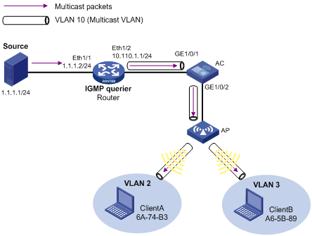
As shown in Figure 5, IGMPv2 is running between Router and AC, and IGMPv2 snooping is running on AC, with Router acting as the IGMP querier.
Create VLAN 10 on AC, assign GigabitEthernet 1/0/1 to VLAN 10, and enable IGMP snooping in the VLAN. Configure GigabitEthernet 1/0/2 as a hybrid port, and configure the port to permit packets from VLAN 2, VLAN 3, and VLAN 10 to pass. Configure aggregate port BAGG 1 as a trunk port, and configure the port to permit packets from VLAN 2, VLAN 3, and VLAN 10 to pass.
Create WLAN-ESS 1 on AC and configure it as a hybrid port with VLAN 10 as the PVID. Configure the port to permit packets from VLAN 2, VLAN 3, and VLAN 10 to pass. Configure the MAC-based VLAN feature so that Client A and Client B belong to VLAN 2 and VLAN 3 respectively.
The multicast source sends multicast data to multicast group 224.1.1.1. Client A and Client B are the receivers of this multicast group.
Configure the port-based multicast VLAN feature so that Router can send multicast data to the receivers connecting with the AC through the multicast VLAN.
Configuration procedure
1. Configure the IP address and subnet mask for each interface, as shown in Figure 5. (Details not shown.)
2. On Router, enable IP multicast routing, enable PIM-DM on each interface, and enable IGMP on the AC-side interface Ethernet 1/2.
<Router> system-view
[Router] multicast routing-enable
[Router] interface ethernet 1/1
[Router-Ethernet1/1] pim dm
[Router-Ethernet1/1] quit
[Router] interface ethernet 1/2
[Router-Ethernet1/2] pim dm
[Router-Ethernet1/2] igmp enable
[Router-Ethernet1/2]quit
3. Configure the AC (for the WX5540E AC engine):
# On the AC configuration interface, enable IGMP snooping globally.
<AC> system-view
[AC] igmp-snooping
[AC-igmp-snooping] quit
# Create VLAN 10, and enable IGMP snooping in this VLAN.
[AC] vlan 10
[AC-vlan10] igmp-snooping enable
[AC-vlan10] quit
# Configure the aggregate interface on AC as a trunk port, and configure it to allow packets from VLAN 2, VLAN 3, and VLAN 10 to pass.
[AC]interface Bridge-Aggregation 1
[AC-Bridge-Aggregation1] port link-type trunk
[AC-Bridge-Aggregation1] port trunk permit vlan 2 3 10
[AC-Bridge-Aggregation1]quit
# Log in to the configuration interface of the switching engine from the AC engine by using the oap command, and enable IGMP snooping globally. Create VLAN 10, assign GigabitEthernet 1/0/1 to this VLAN, and enable IGMP snooping in this VLAN.
<AC> oap connect slot 0
Press CTRL+K to quit.
Connected to OAP!
User interface aux0 is available.
Press ENTER to get started.
<Device> system-view
[Device] igmp-snooping
[Device] vlan 10
[Device-vlan10] port GigabitEthernet 1/0/1
[Device-vlan10] igmp-snooping enable
[Device-vlan10] quit
# Configure GigabitEthernet 1/0/2 as a hybrid port, and configure it to allow packets from VLAN 2, VLAN 3, and VLAN 10 to pass.
[Device]interface GigabitEthernet 1/0/2
[Device-GigabitEthernet1/0/2] port link-type hybrid
[Device-GigabitEthernet1/0/2] port hybrid vlan 2 3 10 tagged
[Device-GigabitEthernet1/0/2] quit
# Use Ctrl + K to return to the configuration interface of the AC engine.
# Create VLAN 2 and VLAN 3.
[AC] vlan 2
[AC-vlan2] vlan 3
[AC-vlan3] quit
# Create WLAN-ESS 1, configure it as a hybrid port, and configure VLAN 10 as the PVID.
[AC] interface WLAN-ESS 1
[AC-WLAN-ESS1] port link-type hybrid
[AC-WLAN-ESS1] port hybrid pvid vlan 10
# Assign WLAN-ESS 1 to VLAN 2, VLAN 3, and VLAN 10, and configure it to send packets from these VLANs without tags.
[AC-WLAN-ESS1] port hybrid vlan 2 3 10 untagged
# Enable the MAC-based VLAN feature on WLAN-ESS 1.
[AC-WLAN-ESS1] mac-vlan enable
# Associate the MAC addresses 6A-74-B3 and A6-5B-89 with VLAN 2 and VLAN 3, respectively so that Client A and Client B belong to VLAN 2 and VLAN 3, respectively.
[AC] mac-vlan mac-address 6A-74-B3 vlan 2
[AC] mac-vlan mac-address A6-5B-89 vlan 3
# Enable IGMP snooping in VLAN 2 and VLAN 3.
[AC] vlan 2
[AC-vlan2] igmp-snooping enable
[AC-vlan2] quit
[AC] vlan 3
[AC-vlan3] igmp-snooping enable
[AC-vlan3] quit
# Configure VLAN 10 as a multicast VLAN.
[AC] multicast-vlan 10
# Assign WLAN-ESS 1 to VLAN 10.
[AC-mvlan-10] port WLAN-ESS 1
[AC-mvlan-10] quit
Verifying the configuration
# Display the multicast VLAN information on the AC.
[AC] display multicast-vlan
Total 1 multicast-vlan(s)
Multicast vlan 10
port list:
WLAN-ESS1
# Display the IGMP snooping multicast group information on the AC.
[AC] display igmp-snooping group
Total 1 IP Group(s).
Total 1 IP Source(s).
Total 1 MAC Group(s).
Port flags: D-Dynamic port, S-Static port, C-Copy port, P-PIM port
Subvlan flags: R-Real VLAN, C-Copy VLAN
Vlan(id):10.
Total 1 IP Group(s).
Total 1 IP Source(s).
Total 1 MAC Group(s).
Router port(s):total 0 port.
IP group(s):the following ip group(s) match to one mac group.
IP group address:224.1.1.1
(0.0.0.0, 224.1.1.1):
Host port(s):total 1 port.
WLAN-DBSS1:1 (D)
MAC group(s):
MAC group address:0100-5e01-0101
Host port(s):total 1 port.
WLAN-DBSS1:1
The output shows that IGMP snooping is maintaining the router ports and member ports in VLAN 10.
Port-based multicast VLAN configuration example (for the WX3000E series)
Network requirements
As shown in Figure 6, IGMPv2 is running between Router and AC, and IGMPv2 snooping is running on AC, with Router acting as the IGMP querier.
Create VLAN 10 on AC, assign GigabitEthernet 1/0/1 to VLAN 10, and enable IGMP snooping in the VLAN. Configure GigabitEthernet 1/0/2 as a hybrid port, and configure the port to permit packets from VLAN 2, VLAN 3, and VLAN 10 to pass. Configure aggregate port BAGG 1 as a trunk port, and configure the port to permit packets from VLAN 2, VLAN 3, and VLAN 10 to pass.
Create WLAN-ESS 1 on AC and configure it as a hybrid port with VLAN 10 as the PVID. Configure the port to permit packets from VLAN 2, VLAN 3, and VLAN 10 to pass. Configure the MAC-based VLAN feature so that Client A and Client B belong to VLAN 2 and VLAN 3 respectively.
The multicast source sends multicast data to multicast group 224.1.1.1. Client A and Client B are the receivers of this multicast group.
Configure the port-based multicast VLAN feature so that Router can send multicast data to the receivers connecting with the AC through the multicast VLAN.
Configuration procedure
1. Configure the IP address and subnet mask for each interface, as shown in Figure 6. (Details not shown.)
2. On Router, enable IP multicast routing, enable PIM-DM on each interface, and enable IGMP on the AC-side interface Ethernet 1/2.
<Router> system-view
[Router] multicast routing-enable
[Router] interface ethernet 1/1
[Router-Ethernet1/1] pim dm
[Router-Ethernet1/1] quit
[Router] interface ethernet 1/2
[Router-Ethernet1/2] pim dm
[Router-Ethernet1/2] igmp enable
[Router-Ethernet1/2]quit
3. Configure the AC (for the WX3024E AC engine):
# On the AC configuration interface, enable IGMP snooping globally.
<AC> system-view
[AC] igmp-snooping
[AC-igmp-snooping] quit
# Create VLAN 10, and enable IGMP snooping in this VLAN.
[AC] vlan 10
[AC-vlan10] igmp-snooping enable
[AC-vlan10] quit
# Configure the aggregate interface on AC as a trunk port, and configure it to allow packets from VLAN 2, VLAN 3, and VLAN 10 to pass.
[AC]interface Bridge-Aggregation 1
[AC-Bridge-Aggregation1] port link-type trunk
[AC-Bridge-Aggregation1] port trunk permit vlan 2 3 10
[AC-Bridge-Aggregation1]quit
# Log in to the configuration interface of the switching engine from the AC engine by using the oap command, and enable IGMP snooping globally. Create VLAN 10, assign GigabitEthernet 1/0/1 to this VLAN, and enable IGMP snooping in this VLAN.
<AC> oap connect slot 0
Press CTRL+K to quit.
Connected to OAP!
User interface aux0 is available.
Press ENTER to get started.
<Device> system-view
[Device] igmp-snooping
[Device] vlan 10
[Device-vlan10] port GigabitEthernet 1/0/1
[Device-vlan10] igmp-snooping enable
[Device-vlan10] quit
# Configure GigabitEthernet 1/0/2 as a hybrid port, and configure it to allow packets from VLAN 2, VLAN 3, and VLAN 10 to pass.
[Device]interface GigabitEthernet 1/0/2
[Device-GigabitEthernet1/0/2] port link-type hybrid
[Device-GigabitEthernet1/0/2] port hybrid vlan 2 3 10 tagged
[Device-GigabitEthernet1/0/2] quit
# Use Ctrl + K to return to the configuration interface of the AC engine.
# Create VLAN 2 and VLAN 3.
[AC] vlan 2
[AC-vlan2] vlan 3
[AC-vlan3] quit
# Create WLAN-ESS 1, configure it as a hybrid port, and configure VLAN 10 as the PVID.
[AC] interface WLAN-ESS 1
[AC-WLAN-ESS1] port link-type hybrid
[AC-WLAN-ESS1] port hybrid pvid vlan 10
# Assign WLAN-ESS 1 to VLAN 2, VLAN 3, and VLAN 10, and configure it to send packets from these VLANs without tags.
[AC-WLAN-ESS1] port hybrid vlan 2 3 10 untagged
# Enable the MAC-based VLAN feature on WLAN-ESS 1.
[AC-WLAN-ESS1] mac-vlan enable
# Associate the MAC addresses 6A-74-B3 and A6-5B-89 with VLAN 2 and VLAN 3, respectively so that Client A and Client B belong to VLAN 2 and VLAN 3, respectively.
[AC] mac-vlan mac-address 6A-74-B3 vlan 2
[AC] mac-vlan mac-address A6-5B-89 vlan 3
# Enable IGMP snooping in VLAN 2 and VLAN 3.
[AC] vlan 2
[AC-vlan2] igmp-snooping enable
[AC-vlan2] quit
[AC] vlan 3
[AC-vlan3] igmp-snooping enable
[AC-vlan3] quit
# Configure VLAN 10 as a multicast VLAN.
[AC] multicast-vlan 10
# Assign WLAN-ESS 1 to VLAN 10.
[AC-mvlan-10] port WLAN-ESS 1
[AC-mvlan-10] quit
Verifying the configuration
# Display the multicast VLAN information on the AC.
[AC] display multicast-vlan
Total 1 multicast-vlan(s)
Multicast vlan 10
port list:
WLAN-ESS1
# Display the IGMP snooping multicast group information on the AC.
[AC] display igmp-snooping group
Total 1 IP Group(s).
Total 1 IP Source(s).
Total 1 MAC Group(s).
Port flags: D-Dynamic port, S-Static port, A-Aggregation port, C-Copy port
Subvlan flags: R-Real VLAN, C-Copy VLAN
Vlan(id):10.
Total 1 IP Group(s).
Total 1 IP Source(s).
Total 1 MAC Group(s).
Router port(s):total 0 port.
IP group(s):the following ip group(s) match to one mac group.
IP group address:224.1.1.1
(0.0.0.0, 224.1.1.1):
Host port(s):total 1 port.
WLAN-DBSS1:1 (D)
MAC group(s):
MAC group address:0100-5e01-0101
Host port(s):total 1 port.
WLAN-DBSS1:1
The output shows that IGMP snooping is maintaining the router ports and member ports in VLAN 10.