- Table of Contents
- Related Documents
-
| Title | Size | Download |
|---|---|---|
| 01-IGMP Snooping Configuration | 602.19 KB |
Basic concepts in IGMP snooping
IGMP snooping configuration task list
Configuring basic IGMP snooping functions
Specifying the IGMP snooping version
Configuring IGMP snooping port functions
Setting aging timers for dynamic ports
Configuring a port as a simulated member host
Enabling IGMP snooping fast-leave processing
Disabling a port from becoming a dynamic router port
Configuring IGMP snooping querier
Enabling IGMP snooping querier
Configuring parameters for IGMP queries and responses
Configuring source IP addresses for IGMP queries
Configuring IGMP snooping proxying
Enabling IGMP snooping proxying
Configuring the source IP addresses for the IGMP messages sent by the proxy
Configuring IGMP snooping policies
Configuring a multicast group filter
Enabling dropping unknown multicast data
Enabling IGMP report suppression
Setting the maximum number of multicast groups that a port can join
Enabling multicast group replacement
Setting the 802.1p precedence for IGMP messages
Enabling the IGMP snooping host tracking function
Displaying and maintaining IGMP snooping
IGMP snooping configuration examples
Multicast delivery to a wireless client (for the WX6000 series)
Multicast delivery to a wireless client (for the WX5540E)
Multicast delivery to a wireless client (for the WX3000E series)
IGMP snooping proxying configuration example
Layer 2 multicast forwarding cannot function
Configured multicast group policy fails to take effect
Configuring IGMP snooping
Overview
IGMP snooping enables Layer 2 devices to establish Layer 2 multicast forwarding tables instead of flooding all multicast packets. To populate the Layer 2 multicast forwarding table, IGMP snooping listens to IGMP messages exchanged between a Layer 3 multicast device and hosts.
By analyzing received IGMP messages, an IGMP snooping-enabled Layer 2 device establishes mappings between ports and multicast MAC addresses, and forwards multicast data based on these mappings.
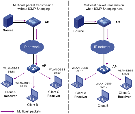
Without IGMP snooping running on the access controller (AC), multicast packets are flooded to wireless clients. When IGMP snooping runs on the AC, multicast packets for known multicast groups are multicast to the wireless clients that need the traffic, rather than being flooded to all wireless clients attached to it. This feature improves bandwidth efficiency, enhances multicast security, and helps per-host accounting for multicast users.
As shown in Figure 1, an access point (AP) joins three different extended service sets (ESSs), corresponding to wireless clients Client A, Client B, and Client C. Without IGMP snooping enabled on the AC, Client A, Client B, and Client C can receive multicast data. With IGMP snooping enabled on the AC, only Client A and Client C can receive multicast data.
For information about WLAN-DBSS interfaces, see WLAN Configuration Guide.
Figure 1 Before and after IGMP snooping is enabled on the AC
Basic concepts in IGMP snooping
This section lists the basic concepts in IGMP snooping.
IGMP snooping related ports
As shown in Figure 2, Router A connects to the multicast source, IGMP snooping runs on Device A and Device B, and Host A and Host C are receiver hosts as members of a multicast group.
Figure 2 IGMP snooping related ports
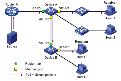
As shown in Figure 2, IGMP snooping divides the ports on a Layer 2 device into the following types:
· Router port—Layer 3 multicast device-side port. Layer 3 multicast devices include DRs and IGMP queriers. In Figure 2, GigabitEthernet 1/0/1 of Device A and GigabitEthernet 1/0/1 of Device B are router ports. The Layer 2 device registers all its local router ports in its router port list.
Do not confuse the "router port" in IGMP snooping with the "routed interface" commonly known as the "Layer 3 interface." The router port in IGMP snooping is the Layer 2 interface.
· Member port—Multicast receiver-side port. In Figure 2, GigabitEthernet 1/0/2 and GigabitEthernet 1/0/3 of Device A and GigabitEthernet 1/0/2 of Device B are member ports. The Layer 2 device registers all the member ports on the local device in its IGMP snooping forwarding table.
Unless otherwise specified, router ports and member ports in this document include both static and dynamic router ports and member ports.
Dynamic router ports include ports that receive IGMP general queries with a source IP address other than 0.0.0.0 and ports that receive PIM hello messages.
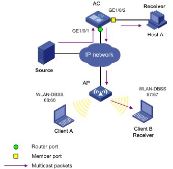
Compared with a common Layer 2 device, an AC has wireless interfaces. The port roles on the access controller in Figure 3 are described as follows:
· Router port—GigabitEthernet 1/0/1 on the AC leads the device toward the multicast source, so GigabitEthernet 1/0/1 is a router port.
· Member port—GigabitEthernet 1/0/2 on the AC connects to a multicast receiver, so GigabitEthernet 1/0/2 is a member port. In addition, after an AP joins an ESS, the AC creates a virtual Layer 2 interface WLAN-DBSS corresponding to that ESS. As shown in Figure 3, after the AP joins two ESSs, the AC creates two virtual Layer 2 interfaces: WLAN-DBSS 67:67 and WLAN-DBSS 68:66. The ESS corresponding to WLAN-DBSS 67:67 comprises a multicast receiver Client B, so WLAN-DBSS 67:67 is a member port.
Figure 3 Port roles on an IGMP snooping–enabled AC
Aging timers for dynamic ports in IGMP snooping
|
Timer |
Description |
Expected message before expiration |
Action after expiration |
|
Dynamic router port aging timer |
When a port receives an IGMP general query with the source address other than 0.0.0.0 or a PIM hello message, the Layer 2 device starts an aging timer for the port. When the timer expires, the dynamic router port ages out. |
IGMP general query with the source address other than 0.0.0.0 or PIM hello. |
The Layer 2 device removes this port from its router port list. |
|
Dynamic member port aging timer |
When a port dynamically joins a multicast group, the Layer 2 device starts an aging timer for the port. When the timer expires, the dynamic member port ages out. |
IGMP membership report. |
The Layer 2 device removes this port from the IGMP snooping forwarding table. |
|
|
NOTE: In IGMP snooping, only dynamic ports age out. Static ports never age out. |
How IGMP snooping works
An IGMP snooping-enabled Layer 2 device performs different actions when it receives different IGMP messages.
The ports in this section are dynamic ports. For information about how to configure and remove static ports, see "Configuring static ports."
When receiving a general query
The IGMP querier periodically sends IGMP general queries (with the destination 224.0.0.1) to all hosts and routers on the local subnet to determine whether any active multicast group members exist on the subnet.
After receiving an IGMP general query, the Layer 2 device forwards it to all ports in the VLAN, except the port that received the query. The Layer 2 device also performs one of the following actions:
· If the receiving port is a dynamic router port in the router port list, restarts the aging timer for the port.
· If the receiving port is not in the router port list, adds it into the router port list as a dynamic router port and starts an aging timer for the port.
When receiving a membership report
A host sends an IGMP report to the IGMP querier for the following purposes:
· Responds to an IGMP query if the host has been a member of a multicast group.
· Applies for a multicast group membership.
After receiving an IGMP report on a port, the Layer 2 device forwards it through all the router ports in the VLAN, resolves the address of the reported multicast group, and performs one of the following actions:
· If no forwarding entry matches the group address, the Layer 2 device creates a forwarding entry for the group, adds the receiving port as a dynamic member port to the forwarding entry, and starts an aging timer for the port.
· If a forwarding entry matches the group address, but the receiving port is not in the forwarding entry for the group, the Layer 2 device adds the port as a dynamic member port to the forwarding entry, and starts an aging timer for the port.
· If a forwarding entry matches the group address and the receiving port is in the forwarding entry for the group, the Layer 2 device restarts the aging timer for the port.
A Layer 2 device does not forward an IGMP report through a non-router port. If the Layer 2 device forwards a report message through a member port, the IGMP report suppression mechanism causes all attached hosts that monitor the reported multicast address to suppress their own reports. This makes the Layer 2 device unable to know whether the reported multicast group still has active members attached to that port.
When receiving a leave message
An IGMPv1 host silently leaves a multicast group and the Layer 2 device is not notified of the leave. However, because the host stops sending IGMP reports as soon as it leaves the multicast group, the Layer 2 device removes the port that connects to the host from the forwarding entry for the multicast group when the aging timer for the port expires.
An IGMPv2 or IGMPv3 host sends an IGMP leave message to the multicast router when leaving a multicast group.
When the Layer 2 device receives an IGMP leave message on a dynamic member port, the Layer 2 device first examines whether a forwarding entry matches the group address in the message. If a match is found, the Layer 2 device examines whether the forwarding entry for the group contains the dynamic member port.
· If no forwarding entry matches the group address, or if the forwarding entry does not contain the port, the Layer 2 device directly discards the IGMP leave message.
· If a forwarding entry matches the group address and the forwarding entry contains the port, the Layer 2 device forwards the leave message to all router ports in the VLAN. Because the Layer 2 device does not know whether any other hosts attached to the port are still listening to that group address, the Layer 2 device does not immediately remove the port from the forwarding entry for that group. Instead, it restarts the aging timer for the port.
After receiving the IGMP leave message on a port, the IGMP querier resolves the multicast group address in the message and sends an IGMP group-specific query to the multicast group through the receiving port. After receiving the IGMP group-specific query, the Layer 2 device forwards it through all its router ports in the VLAN and all member ports of the multicast group. The Layer 2 device also performs the following judgment for the port that received the IGMP leave message:
· If the port (assuming that it is a dynamic member port) receives an IGMP report in response to the group-specific query before its aging timer expires, it means that some host attached to the port is receiving or expecting to receive multicast data for the multicast group. The Layer 2 device restarts the aging timer for the port.
· If the port receives no IGMP report in response to the group-specific query before its aging timer expires, it means that no hosts attached to the port are still listening to that group address. The Layer 2 device removes the port from the forwarding entry for the multicast group when the aging timer expires.
IGMP snooping proxying
You can configure the IGMP snooping proxying function on an edge device to reduce the number of IGMP reports and leave messages sent to its upstream device. The device configured with IGMP snooping proxying is called an IGMP snooping proxy. It is a host from the perspective of its upstream device.
Even though an IGMP snooping proxy is a host from the perspective of its upstream device, the IGMP membership report suppression mechanism for hosts does not affect it.
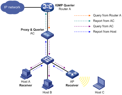
As shown in Figure 4, AC works as an IGMP snooping proxy. As a host from the perspective of the querier Router A, AC represents its attached hosts to send membership reports and leave messages to Router A.
Table 1 IGMP message processing on an IGMP snooping proxy
|
IGMP message |
Actions |
|
General query |
When receiving an IGMP general query, the proxy forwards it to all ports except the port that receives the query. In addition, the proxy generates a report according to the group membership that it maintains and sends the report out of all router ports. |
|
Group-specific query |
In response to the IGMP group-specific query for a certain multicast group, the proxy sends the report to the group out of all router ports if the forwarding entry for the group still contains a member port. |
|
Report |
After receiving a report for a multicast group, the proxy looks up the multicast forwarding table for the forwarding entry for the multicast group. · If a forwarding entry matches the multicast group and contains the receiving port as a dynamic member port, the proxy restarts the aging timer for the port. · If a forwarding entry matches the multicast group but does not contain the receiving port, the proxy adds the port to the forwarding entry as a dynamic member port and starts an aging timer for the port. · If no forwarding entry matches the multicast group, the proxy creates a forwarding entry for the multicast group, adds the receiving port to the forwarding entry as a dynamic member port, and starts an aging timer for the port. |
|
Leave |
In response to an IGMP leave message for a multicast group, the proxy sends a group-specific query out of the receiving port. After making sure that no member port is contained in the forwarding entry for the multicast group, the proxy sends a leave message to the group out of all router ports. |
Protocols and standards
RFC 4541, Considerations for Internet Group Management Protocol (IGMP) and Multicast Listener Discovery (MLD) Snooping Switches
IGMP snooping configuration task list
For the configuration tasks in this section, the following rules apply:
· The configurations made in IGMP-snooping view are effective on all VLANs. The configurations made in VLAN view are effective on only the current VLAN. For a given VLAN, a configuration made in IGMP-snooping view is effective only if you do not make the same configuration in VLAN view.
· The configurations made in IGMP-snooping view are effective on all ports. The configurations made in Layer 2 Ethernet interface view or Layer 2 aggregate interface view are effective on only the current port. The configurations made in port group view are effective on all ports in only the current port group. For a given port, a configuration made in IGMP-snooping view is effective only if you do not make the same configuration in Layer 2 Ethernet interface view, Layer 2 aggregate interface view, or port group view.
Complete these tasks to configure IGMP snooping:
|
Task |
Remarks |
|
|
Required. |
||
|
Optional. |
||
|
Optional. |
||
|
Optional. |
||
|
Optional. |
||
|
Optional. |
||
|
Optional. |
||
|
Optional. |
||
|
Optional. |
||
|
Optional. |
||
|
Optional. |
||
|
Configuring the source IP addresses for the IGMP messages sent by the proxy |
Optional. |
|
|
Optional. |
||
|
Optional. |
||
|
Optional. |
||
|
Setting the maximum number of multicast groups that a port can join |
Optional. |
|
|
Optional. |
||
|
Optional. |
||
|
Optional. |
||
|
Optional. |
||
Configuring basic IGMP snooping functions
This section describes how to configure basic IGMP snooping functions.
Configuration prerequisites
Before you configure basic IGMP snooping functions, complete the following tasks:
· Configure the corresponding VLANs.
· Determine the version of IGMP snooping.
Enabling IGMP snooping
When you enable IGMP snooping, follow these guidelines:
· Enable IGMP snooping globally before you enable it for a VLAN.
· IGMP snooping for a VLAN works on only the Ethernet ports and WLAN-ESS interfaces within that VLAN.
To enable IGMP snooping:
|
Step |
Command |
Remarks |
|
1. Enter system view. |
system-view |
N/A |
|
2. Enable IGMP snooping globally and enter IGMP-snooping view. |
igmp-snooping |
Disabled by default. |
|
3. Return to system view. |
quit |
N/A |
|
4. Enter VLAN view. |
vlan vlan-id |
N/A |
|
5. Enable IGMP snooping in the VLAN. |
igmp-snooping enable |
Disabled by default. |
Specifying the IGMP snooping version
Different versions of IGMP snooping process different versions of IGMP messages:
· IGMPv2 snooping processes IGMPv1 and IGMPv2 messages. However, it floods IGMPv3 messages in the VLAN instead of processing them.
· IGMPv3 snooping processes IGMPv1, IGMPv2, and IGMPv3 messages.
If you change IGMPv3 snooping to IGMPv2 snooping, the system does the following:
· Clears all IGMP snooping forwarding entries that are dynamically added.
· Keeps static IGMPv3 snooping forwarding entries (*, G).
· Clears static IGMPv3 snooping forwarding entries (S, G), which will be restored when IGMP snooping is switched back to IGMPv3 snooping.
For more information about static joins, see "Configuring static ports."
To specify the IGMP snooping version:
|
Step |
Command |
Remarks |
|
1. Enter system view. |
system-view |
N/A |
|
2. Enter VLAN view. |
vlan vlan-id |
N/A |
|
3. Specify the IGMP snooping version. |
igmp-snooping version version-number |
IGMPv2 snooping by default. |
Configuring IGMP snooping port functions
This section describes how to configure IGMP snooping port functions.
Configuration prerequisites
Before you configure IGMP snooping port functions, complete the following tasks:
· Enable IGMP snooping for the VLAN.
· Configure the corresponding port groups.
· Determine the aging timer for dynamic router ports.
· Determine the aging timer for dynamic member ports.
· Determine the multicast group and multicast source addresses.
Setting aging timers for dynamic ports
If an AC does not receive IGMP general queries or PIM hello messages on a dynamic router port when the aging timer of the port expires, the AC removes the port from the router port list.
If the AC receives no IGMP reports for a multicast group on a dynamic member port when the aging timer of the port expires, the AC removes the port from the multicast forwarding entry for that multicast group.
If the memberships of multicast groups change frequently, you can set a relatively small value for the aging timer of the dynamic member ports. If the memberships of multicast groups change rarely, you can set a relatively large value.
Setting aging timers for dynamic ports globally
|
Step |
Command |
Remarks |
|
1. Enter system view. |
system-view |
N/A |
|
2. Enter IGMP-snooping view. |
igmp-snooping |
N/A |
|
3. Set the aging timer for the dynamic router ports. |
router-aging-time interval |
105 seconds by default. |
|
4. Set the aging timer for the dynamic member ports. |
host-aging-time interval |
260 seconds by default. |
Setting aging timers for the dynamic ports in a VLAN
|
Step |
Command |
Remarks |
|
1. Enter system view. |
system-view |
N/A |
|
2. Enter VLAN view. |
vlan vlan-id |
N/A |
|
3. Set the aging timer for the dynamic router ports. |
igmp-snooping router-aging-time interval |
105 seconds by default. |
|
4. Set the aging timer for the dynamic member ports. |
igmp-snooping host-aging-time interval |
260 seconds by default. |
Configuring static ports
If all hosts attached to a port are interested in the multicast data addressed to a particular multicast group or the multicast data that a particular multicast source sends to a particular group, you can configure the port as a static member port for the specified multicast group or the specified multicast source and group.
You can also configure a port to be a static router port, through which the AC can forward all the multicast traffic that it received.
Configuration guidelines
· A static (S, G) entry for a port takes effect only if a valid multicast source address is specified and IGMPv3 snooping is running on the AC.
· A static member port does not respond to queries from the IGMP querier. When you configure a port as a static member port or cancel this configuration on the port, the port does not unsolicitedly send any IGMP report or an IGMP leave message.
· Static member ports and static router ports never age out. To remove such a port, use the corresponding undo command.
Configuration procedure
To configure static ports:
|
Step |
Command |
Remarks |
|
1. Enter system view. |
system-view |
N/A |
|
2. Enter Layer 2 Ethernet interface view or Layer 2 aggregate interface view, or enter port group view. |
· Enter Layer 2 Ethernet interface view or Layer
2 aggregate interface view: · Enter port group view: |
Use either command. |
|
3. Configure the port as a static member port. |
igmp-snooping static-group group-address [ source-ip source-address ] vlan vlan-id |
No static member ports exist by default. |
|
4. Configure the port as a static router port. |
igmp-snooping static-router-port vlan vlan-id |
No static router ports exist by default. |
Configuring a port as a simulated member host
Generally, a host that runs IGMP can respond to IGMP queries. If a host fails to respond, the multicast router might deem that no member of this multicast group exists on the subnet, and removes the corresponding forwarding path.
To avoid this situation, you can configure the port as a simulated member host for a multicast group. When the simulated member host receives an IGMP query, it gives a response. Therefore, the AC can continue receiving multicast data.
A simulated host is equivalent to an independent host in the following ways:
· If a port is configured as a simulated member host, the AC sends an unsolicited IGMP report through the port, and responds to IGMP general queries with IGMP reports through the port.
· If you disable the simulated joining function on the port, the AC sends an IGMP leave message through the port.
To configure a port as a simulated member host:
|
Step |
Command |
Remarks |
|
1. Enter system view. |
system-view |
N/A |
|
2. Enter Layer 2 Ethernet interface view or Layer 2 aggregate interface view, or enter port group view. |
· Enter Layer 2 Ethernet interface view or Layer
2 aggregate interface view: · Enter port group view: |
Use either command. |
|
3. Configure the port as a simulated member host. |
igmp-snooping host-join group-address [ source-ip source-address ] vlan vlan-id |
Not configured by default. |
|
|
NOTE: Unlike a static member port, a port configured as a simulated member host ages out like a dynamic member port. |
Enabling IGMP snooping fast-leave processing
On a port that has only one host attached, you can enable fast-leave processing to save bandwidth and resources. However, on a port that has multiple hosts attached, you should not enable fast-leave processing if you have enabled dropping unknown multicast data globally or for the port. Otherwise, if a host on the port leaves a multicast group, the other hosts attached to the port in the same multicast group cannot receive the multicast data for the group.
Enabling IGMP snooping fast-leave processing globally
|
Step |
Command |
Remarks |
|
1. Enter system view. |
system-view |
N/A |
|
2. Enter IGMP-snooping view. |
igmp-snooping |
N/A |
|
3. Enable IGMP snooping fast-leave processing. |
fast-leave [ vlan vlan-list ] |
Disabled by default. |
Enabling IGMP snooping fast-leave processing on a port
|
Step |
Command |
Remarks |
|
1. Enter system view. |
system-view |
N/A |
|
2. Enter Layer 2 Ethernet interface view or Layer 2 aggregate interface view, or enter port group view. |
· Enter Layer 2 Ethernet interface view or Layer
2 aggregate interface view: · Enter port group view: |
Use either command. |
|
3. Enable IGMP snooping fast-leave processing for the port. |
igmp-snooping fast-leave [ vlan vlan-list ] |
Disabled by default. |
Disabling a port from becoming a dynamic router port
The following problems might exist in a multicast access network:
· After receiving an IGMP general query or a PIM hello message from a connected host, a router port becomes a dynamic router port. Before its timer expires, this dynamic router port receives all multicast packets within the VLAN where the port belongs and forwards them to the host, affecting normal multicast reception of the host.
· The IGMP general query or PIM hello message that the host sends affects the multicast routing protocol state on Layer 3 devices, such as the IGMP querier or DR election, and might further cause network interruption.
To solve these problems and improve network security and the control over multicast users, disable that router port from becoming a dynamic router port after the port receives an IGMP general query or a PIM hello message.
To disable a port from becoming a dynamic router port:
|
Step |
Command |
Remarks |
|
1. Enter system view. |
system-view |
N/A |
|
2. Enter Layer 2 Ethernet interface view or Layer 2 aggregate interface view, or enter port group view. |
· Enter Layer 2 Ethernet interface view or Layer
2 aggregate interface view: · Enter port group view: |
Use either command. |
|
3. Disable the port from becoming a dynamic router port. |
igmp-snooping router-port-deny [ vlan vlan-list ] |
By default, a port can become a dynamic router port. This configuration does not affect the static router port configuration. |
Configuring IGMP snooping querier
This section describes how to configure IGMP snooping querier.
Configuration prerequisites
Before you configure IGMP snooping querier, complete the following tasks:
· Enable IGMP snooping in the VLAN.
· Determine the interval for sending IGMP general queries.
· Determine the IGMP last-member query interval.
· Determine the maximum response delay for IGMP general queries.
· Determine the source address of IGMP general queries.
· Determine the source address of IGMP group-specific queries.
Enabling IGMP snooping querier
However, a Layer 2 multicast device does not support IGMP, and therefore cannot send general queries by default. When you configure an IGMP snooping querier on a Layer 2 device in a VLAN where multicast traffic is switched only at Layer 2 and no multicast routers are present, the Layer 2 device sends IGMP queries, so that multicast forwarding entries can be established and maintained at the data link layer.
Do not configure an IGMP snooping querier on a multicast network that runs IGMP. Although an IGMP snooping querier does not take part in IGMP querier elections, it might affect IGMP querier elections because it sends IGMP general queries with a low source IP address.
To enable IGMP snooping querier:
|
Step |
Command |
Remarks |
|
1. Enter system view. |
system-view |
N/A |
|
2. Enter VLAN view. |
vlan vlan-id |
N/A |
|
3. Enable IGMP snooping querier. |
igmp-snooping querier |
Disabled by default. |
Configuring parameters for IGMP queries and responses
|
|
CAUTION: Make sure the interval for sending IGMP general queries is larger than the maximum response delay for IGMP general queries. Otherwise, multicast group members might be deleted by mistake. |
You can modify the IGMP general query interval based on actual condition of the network.
A multicast listening host starts a timer for each multicast group that it has joined when it receives an IGMP query (general query or group-specific query). This timer is initialized to a random value in the range of 0 to the maximum response delay advertised in the IGMP query message. When the timer value decreases to 0, the host sends an IGMP report to the multicast group.
To speed up the response of hosts to IGMP queries and avoid simultaneous timer expirations causing IGMP report traffic bursts, you must properly set the maximum response delay.
· The maximum response delay for IGMP general queries is set by the max-response-time command.
· The maximum response delay for IGMP group-specific queries equals the IGMP last-member query interval.
Configuring the global parameters for IGMP queries and responses
|
Step |
Command |
Remarks |
|
1. Enter system view. |
system-view |
N/A |
|
2. Enter IGMP-snooping view. |
igmp-snooping |
N/A |
|
3. Set the maximum response delay for IGMP general queries. |
max-response-time interval |
10 seconds by default. |
|
4. Set the IGMP last-member query interval. |
last-member-query-interval interval |
1 second by default. |
Configuring the parameters for IGMP queries and responses in a VLAN
|
Step |
Command |
Remarks |
|
1. Enter system view. |
system-view |
N/A |
|
2. Enter VLAN view. |
vlan vlan-id |
N/A |
|
3. Set the interval for sending IGMP general queries. |
igmp-snooping query-interval interval |
60 seconds by default. |
|
4. Set the maximum response delay for IGMP general queries. |
igmp-snooping max-response-time interval |
10 seconds by default. |
|
5. Set the IGMP last-member query interval. |
igmp-snooping last-member-query-interval interval |
1 second by default. |
Configuring source IP addresses for IGMP queries
After an AC receives an IGMP query whose source IP address is 0.0.0.0 on a port, it does not enlist that port as a dynamic router port. This might prevent multicast forwarding entries from being correctly created at the data link layer and eventually cause multicast traffic forwarding to fail. To avoid this problem, when an AC acts as the IGMP snooping querier, H3C recommends that you configure a non-all-zero IP address as the source IP address of IGMP queries.
Changing the source address of IGMP queries might affect the IGMP querier election within the subnet.
To configure source IP addresses for IGMP queries:
|
Step |
Command |
Remarks |
|
1. Enter system view. |
system-view |
N/A |
|
2. Enter VLAN view. |
vlan vlan-id |
N/A |
|
3. Configure the source IP address for IGMP general queries. |
igmp-snooping general-query source-ip { ip-address | current-interface } |
0.0.0.0 by default. |
|
4. Configure the source IP address for IGMP group-specific queries. |
igmp-snooping special-query source-ip { ip-address | current-interface } |
0.0.0.0 by default. |
Configuring IGMP snooping proxying
This section describes how to configure IGMP snooping proxying.
Configuration prerequisites
Before you configure IGMP snooping proxying in a VLAN, complete the following tasks:
· Enable IGMP snooping for the VLAN.
· Determine the source IP address for the IGMP reports sent by the proxy.
· Determine the source IP address for the IGMP leave messages sent by the proxy.
Enabling IGMP snooping proxying
The IGMP snooping proxying function works on a per-VLAN basis. After you enable the function in a VLAN, AC works as the IGMP snooping proxy for the downstream hosts and upstream router in the VLAN.
To enable IGMP snooping proxying in a VLAN:
|
Step |
Command |
Remarks |
|
1. Enter system view. |
system-view |
N/A |
|
2. Enter VLAN view. |
vlan vlan-id |
N/A |
|
3. Enable IGMP snooping proxying in the VLAN. |
igmp-snooping proxying enable |
Disabled by default. |
Configuring the source IP addresses for the IGMP messages sent by the proxy
You can set the source IP addresses for the IGMP reports and leave messages that the IGMP snooping proxy sends on behalf of its attached hosts.
To configure the source IP addresses for the IGMP messages sent by the proxy in a VLAN:
|
Step |
Command |
Remarks |
|
1. Enter system view. |
system-view |
N/A |
|
2. Enter VLAN view. |
vlan vlan-id |
N/A |
|
3. Configure the source IP address for the IGMP reports that the proxy sends. |
igmp-snooping report source-ip { ip-address | current-interface } |
The default is 0.0.0.0. |
|
4. Configure the source IP address for the IGMP leave messages that the proxy sends. |
igmp-snooping leave source-ip { ip-address | current-interface } |
The default is 0.0.0.0. |
Configuring IGMP snooping policies
This section describes how to configure IGMP snooping policies.
Configuration prerequisites
Before you configure IGMP snooping policies, complete the following tasks:
· Enable IGMP snooping for the VLAN.
· Determine the ACL rule for multicast group filtering.
· Determine the maximum number of multicast groups that a port can join.
· Determine the 802.1p precedence for IGMP messages.
Configuring a multicast group filter
On an IGMP snooping-enabled AC, you can configure a multicast group filter to limit multicast programs available to users.
In an application, when a user requests a multicast program, the user's host initiates an IGMP report. After receiving this report message, the AC resolves the multicast group address in the report and looks up the ACL. If a match is found to permit the port that received the report to join the multicast group, the AC creates an IGMP snooping forwarding entry for the multicast group and adds the port to the forwarding entry. Otherwise, the AC drops this report message. In this case, the multicast data for the multicast group is not sent to this port, and the user cannot retrieve the program.
Configuring a multicast group filter globally
|
Step |
Command |
Remarks |
|
1. Enter system view. |
system-view |
N/A |
|
2. Enter IGMP-snooping view. |
igmp-snooping |
N/A |
|
3. Configure a multicast group filter globally. |
group-policy acl-number [ vlan vlan-list ] |
By default, no group filter is globally configured. That is, a host can join any valid multicast group. |
Configuring a multicast group filter on a port
|
Step |
Command |
Remarks |
|
1. Enter system view. |
system-view |
N/A |
|
2. Enter Layer 2 Ethernet interface view or Layer 2 aggregate interface view, or enter port group view. |
· Enter Layer 2 Ethernet interface view or Layer
2 aggregate interface view: · Enter port group view: |
Use either command. |
|
3. Configure a multicast group filter. |
igmp-snooping group-policy acl-number [ vlan vlan-list ] |
By default, no group filter is configured on the current port. That is, the hosts on this port can join any valid multicast group. |
Enabling dropping unknown multicast data
Unknown multicast data refers to multicast data for which no forwarding entries exist in the IGMP snooping forwarding table. When the AC receives such multicast traffic, one of the following occurs:
· If the function of dropping unknown multicast data is disabled, the AC floods unknown multicast data in the VLAN to which the unknown multicast data belongs.
· If the function of dropping unknown multicast data is enabled, the AC drops all received unknown multicast data.
Configuration guidelines
· The drop-unknown command and the igmp-snooping drop-unknown command are mutually exclusive. Do not configure them at the same time.
· When enabled to drop unknown IPv4 multicast data, the AC is automatically enabled to drop unknown IPv6 multicast data.
Enabling dropping unknown multicast data globally
|
Step |
Command |
Remarks |
|
1. Enter system view. |
system-view |
N/A |
|
2. Enter IGMP-snooping view. |
igmp-snooping |
N/A |
|
3. Enable dropping unknown multicast data globally. |
drop-unknown |
Disabled by default. |
Enabling dropping unknown multicast data in a VLAN
|
Step |
Command |
Remarks |
|
1. Enter system view. |
system-view |
N/A |
|
2. Enter VLAN view. |
vlan vlan-id |
N/A |
|
3. Enable dropping unknown multicast data. |
igmp-snooping drop-unknown |
Disabled by default. |
Enabling IGMP report suppression
When a Layer 2 device receives an IGMP report from a multicast group member, the device forwards the message to the Layer 3 device that directly connects to the Layer 2 device. When multiple members of a multicast group are attached to the Layer 2 device, the Layer 3 device might receive duplicate IGMP reports for the multicast group from these members.
With the IGMP report suppression function enabled, within each query interval, the Layer 2 device forwards only the first IGMP report for the multicast group to the Layer 3 device. It does not forward the subsequent IGMP reports for the same multicast group. This helps reduce the number of packets being transmitted over the network.
On an IGMP snooping proxy, IGMP reports for a multicast group from downstream hosts are suppressed if the forwarding entry for the multicast group exists on the proxy, whether the suppression function is enabled or not.
To enable IGMP report suppression:
|
Step |
Command |
Remarks |
|
1. Enter system view. |
system-view |
N/A |
|
2. Enter IGMP-snooping view. |
igmp-snooping |
N/A |
|
3. Enable IGMP report suppression. |
report-aggregation |
Enabled by default. |
Setting the maximum number of multicast groups that a port can join
You can set the maximum number of multicast groups that a port can join to regulate traffic on the port.
When you configure this maximum number, if the number of multicast groups the port has joined exceeds the configured maximum value, the system deletes all the forwarding entries for the port from the IGMP snooping forwarding table, and the hosts on this port join multicast groups again until the number of multicast groups that the port joins reaches the maximum value. When the port joins a multicast group, if the port has been configured as a static member port, the system applies the configurations to the port again. If you have configured simulated joining on the port, the system establishes corresponding forwarding entry for the port after receiving a report from the simulated member host.
To set the maximum number of multicast groups that a port can join:
|
Step |
Command |
Remarks |
|
1. Enter system view. |
system-view |
N/A |
|
2. Enter Layer 2 Ethernet interface view or Layer 2 aggregate interface view, or enter port group view. |
· Enter Layer 2 Ethernet interface view or Layer
2 aggregate interface view: · Enter port group view: |
Use either command. |
|
3. Set the maximum number of multicast groups that the port can join. |
igmp-snooping group-limit limit [ vlan vlan-list ] |
By default, the upper limit is 256. |
Enabling multicast group replacement
For various reasons, the number of multicast groups that the AC or a port joins might exceed the upper limit. In addition, in some specific applications, a multicast group that the AC newly joins must replace an existing multicast group automatically. A typical example is channel switching. To view a new channel, a user switches from the current multicast group to the new one.
To realize such requirements, you can enable the multicast group replacement function on the AC or on a certain port. When the number of multicast groups that the AC or on the port has joined reaches the limit, one of the following occurs:
· If the multicast group replacement feature is disabled, new IGMP reports are automatically discarded.
· If the multicast group replacement feature is enabled, the multicast group that the AC or the port newly joins automatically replaces an existing multicast group that has the lowest address.
|
|
IMPORTANT: Be sure to configure the maximum number of multicast groups that a port can join to a value other than the default one (see "Setting the maximum number of multicast groups that a port can join") before enabling multicast group replacement. Otherwise, the multicast group replacement functionality will not take effect. |
Enabling multicast group replacement globally
|
Step |
Command |
Remarks |
|
1. Enter system view. |
system-view |
N/A |
|
2. Enter IGMP-snooping view. |
igmp-snooping |
N/A |
|
3. Enable multicast group replacement. |
overflow-replace [ vlan vlan-list ] |
Disabled by default. |
Enabling multicast group replacement on a port
|
Step |
Command |
Remarks |
|
1. Enter system view. |
system-view |
N/A |
|
2. Enter Layer 2 Ethernet interface view or Layer 2 aggregate interface view, or enter port group view. |
· Enter Layer 2 Ethernet interface view or Layer
2 aggregate interface view: · Enter port group view: |
Use either command. |
|
3. Enable multicast group replacement. |
igmp-snooping overflow-replace [ vlan vlan-list ] |
Disabled by default. |
Setting the 802.1p precedence for IGMP messages
When congestion occurs on outgoing ports of the Layer 2 device, it forwards IGMP messages in their 802.1p priority order, from highest to lowest. You can assign higher forwarding priority to IGMP messages by changing their 802.1p precedence.
Setting the 802.1p precedence for IGMP messages globally
|
Step |
Command |
Remarks |
|
1. Enter system view. |
system-view |
N/A |
|
2. Enter IGMP-snooping view. |
igmp-snooping |
N/A |
|
3. Set the 802.1p precedence for IGMP messages. |
dot1p-priority priority-number |
The default 802.1p precedence for IGMP messages is 0. The global configuration takes effect on all VLANs. |
Setting the 802.1p precedence for IGMP messages in a VLAN
|
Step |
Command |
Remarks |
|
1. Enter system view. |
system-view |
N/A |
|
2. Enter VLAN view. |
vlan vlan-id |
N/A |
|
3. Set the 802.1p precedence for IGMP messages in the VLAN. |
igmp-snooping dot1p-priority priority-number |
The default 802.1p precedence for IGMP messages is 0. |
Enabling the IGMP snooping host tracking function
With the IGMP snooping host tracking function, the AC can record the information of the member hosts that are receiving multicast traffic, including the host IP address, running duration, and timeout time. You can monitor and manage the member hosts according to the recorded information.
Enabling the IGMP snooping host tracking function globally
|
Step |
Command |
Remarks |
|
1. Enter system view. |
system-view |
N/A |
|
2. Enter IGMP-snooping view. |
igmp-snooping |
N/A |
|
3. Enable the IGMP snooping host tracking function globally. |
host-tracking |
Disabled by default. |
Enabling the IGMP snooping host tracking function in a VLAN
|
Step |
Command |
Remarks |
|
1. Enter system view. |
system-view |
N/A |
|
2. Enter VLAN view. |
vlan vlan-id |
N/A |
|
3. Enable the IGMP snooping host tracking function in the VLAN. |
igmp-snooping host-tracking |
Disabled by default. |
Enabling the PIM hello proxy
This feature enables the device to forward the last PIM hello message received from the wire-connected downstream PIM router through the new active mesh link after a mesh link switchover. When the upstream device receives the message, it maintains the receiving port as a router port and forwards subsequent multicast traffic through the new active mesh link.
This feature is typically used on vehicle-mounted APs in the wireless mesh network.
To enable the PIM hello proxy:
|
Step |
Command |
Remarks |
|
1. Enter system view. |
system-view |
N/A |
|
2. Enter VLAN view. |
vlan vlan-id |
N/A |
|
3. Enable the PIM hello proxy. |
igmp-snooping pim-hello-proxy enable |
Disabled by default. |
Displaying and maintaining IGMP snooping
Execute display commands in any view and reset commands in user view.
|
Task |
Command |
Remarks |
|
Display IGMP snooping group information. |
display igmp-snooping group [ vlan vlan-id ] [ verbose ] [ | { begin | exclude | include } regular-expression ] |
Available in any view. |
|
Display information about the hosts tracked by IGMP snooping. |
display igmp-snooping host vlan vlan-id group group-address [ source source-address ] [ | { begin | exclude | include } regular-expression ] |
Available in any view. |
|
Display statistics for the IGMP messages learned through IGMP snooping. |
display igmp-snooping statistics [ | { begin | exclude | include } regular-expression ] |
Available in any view. |
|
Remove all the dynamic group entries of a specified IGMP snooping group or all IGMP snooping groups. |
reset igmp-snooping group { group-address | all } [ vlan vlan-id ] |
Available in user view. This command removes only dynamic group entries. |
|
Clear statistics for the IGMP messages learned through IGMP snooping. |
reset igmp-snooping statistics |
Available in user view. |
|
|
NOTE: The reset igmp group command cannot remove static IGMP group entries. |
IGMP snooping configuration examples
ACs have either 10 GE or GE interfaces. Table 2 identifies the Ethernet interfaces on different types of ACs.
|
|
NOTE: If the AC is an AC module installed on a switch, make sure the internal Ethernet interface that connects the switch to the AC module has correct settings, including in particular VLAN settings. |
Table 2 AC Ethernet interfaces
|
Hardware |
AC Ethernet interfaces |
|
AC modules (installed in a switch) |
|
|
LSQM1WCMD0 LSRM1WCM3A1 LSUM3WCMD0 LSUM1WCME0 |
The internal Ethernet interface that connects the AC module to the switch. |
|
Wireless switches |
|
|
WX3024E WX3010E |
The internal Ethernet interface that connects the AC engine to the switching engine. |
|
ACs |
|
|
WX6103 |
The internal Ethernet interface that connects the main control board to the switching board. |
|
WX5002V2 WX5004 WX3510E WX3540E WX5510E |
Any Ethernet interfaces on the AC. |
|
WX2540E WAC360 WAC361 |
Any LAN or WAN interfaces on the AC. |
|
WX5540E |
The internal Ethernet interface that connects the AC engine to the switching engine. |
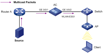
Multicast delivery to a wireless client (for the WX5000 series/WX3500E series/WX5510E/WX2540E/WAC360 series)
Network requirements
As shown in Figure 5, the multicast source 1.1.1.1/24 sends multicast traffic to multicast group 224.1.1.1. The client is a member of the multicast group.
The client and the source can communicate with each other and the client can receive multicast traffic from the source.

Configuration procedure
1. Enable PIM-DM and IGMP on the port of Router A that connects to AC and enable multicast routing globally.
2. Configure WLAN services:
# Configure the WLAN-ESS interface and assign WLAN ESS 1 to VLAN 100.
<AC>system-view
[AC]Vlan 100
[AC-vlan100]quit
[AC]interface WLAN-ESS 1
[AC-WLAN-ESS1]port access vlan 100
[AC-WLAN-ESS1]quit
# Configure a WLAN service template with its SSID as multicast and authentication method as open-system. Bind the WLAN-ESS interface with the service template.
[AC]wlan service-template 1 clear
[AC-wlan-st-1]ssid Multicast
[AC-wlan-st-1]bind WLAN-ESS 1
[AC-wlan-st-1]authentication-method open-system
[AC-wlan-st-1]service-template enable
[AC-wlan-st-1]quit
# Create AP template ap of model WA3628i-AGN and configure its serial ID as 210235A29G007C000020 on AC.
[AC]wlan ap ap model WA3628i-AGN
[AC-wlan-ap-ap]serial-id 210235A29G007C000020
# Configure the mapping between the service template and the current radio.
[AC-wlan-ap-ap]radio 1
[AC-wlan-ap-ap-radio-1]service-template 1
[AC-wlan-ap-ap-radio-1]radio enable
[AC-wlan-ap-ap-radio-1]quit
[AC-wlan-ap-ap]quit
3. Configure the wireless client to join the multicast group:
# Enable IGMP snooping and specify IGMPv3 snooping in VLAN 100.
[AC]igmp-snooping
[AC-igmp-snooping]quit
[AC]vlan 100
[AC-vlan100]igmp-snooping enable
[AC-vlan100]igmp-snooping version 3
[AC-vlan100]quit
# Configure GigabitEthernet 1/0/2 as a trunk port and assign it to VLAN 100.
[AC] interface GigabitEthernet 1/0/2
[AC-GigabitEthernet1/0/2] port link-type trunk
[AC-GigabitEthernet1/0/2] port trunk permit vlan 100
[AC-GigabitEthernet1/0/2] quit
# Configure the client to access the WLAN service and request multicast traffic destined for 224.1.1.1.
Verifying the configuration
# Display detailed IGMP snooping group information in VLAN 100 on AC after the client sends an IGMP report for multicast group 224.1.1.1.
[AC]display igmp-snooping group vlan 100 verbose
Total 1 IP Group(s).
Total 1 IP Source(s).
Total 1 MAC Group(s).
Port flags: D-Dynamic port, S-Static port, C-Copy port
Subvlan flags: R-Real VLAN, C-Copy VLAN
Vlan(id):100.
Total 1 IP Group(s).
Total 1 IP Source(s).
Total 1 MAC Group(s).
Router port(s):total 1 port(s).
GigabitEthernet1/0/1 (D) ( 00:01:30 )
IP group(s):the following ip group(s) match to one mac group.
IP group address:224.1.1.1
(0.0.0.0, 224.1.1.1):
Attribute: Host Port
Host port(s):total 1 port(s).
WLAN-DBSS1:0 (D) ( 00:04:17 )
MAC group(s):
MAC group address:0100-5e01-0101
Host port(s):total 1 port(s).
WLAN-DBSS1:0
The output shows that WLAN-DBSS1:0 on AC joins the multicast group 224.1.1.1.
Multicast delivery to a wireless client (for the WX6000 series)
Network requirements
As shown in Figure 6, the multicast source 1.1.1.1/24 sends multicast traffic to multicast group 224.1.1.1. The client is a member of the multicast group.
The client and the source can communicate with each other and the client can receive multicast traffic from the source.
Configuration procedure (for the WX6103)
1. Configure WLAN services:
# Configure WLAN-ESS interface 1 and assign it to VLAN 100.
<AC>system-view
[AC]Vlan 100
[AC-vlan100]quit
[AC]interface WLAN-ESS 1
[AC-WLAN-ESS1]port access vlan 100
[AC-WLAN-ESS1]quit
# Configure a WLAN service template with its SSID as multicast and authentication method as open-system. Bind the WLAN-ESS interface with the service template.
[AC]wlan service-template 1 clear
[AC-wlan-st-1]ssid Multicast
[AC-wlan-st-1]bind WLAN-ESS 1
[AC-wlan-st-1]authentication-method open-system
[AC-wlan-st-1]service-template enable
[AC-wlan-st-1]quit
# Create AP template ap of model WA3628i-AGN and configure its serial ID as 210235A29G007C000020 on the AC (WX6103 main control board).
[AC]wlan ap ap model WA3628i-AGN
[AC-wlan-ap-ap]serial-id 210235A29G007C000020
# Configure the mapping between the service template and the current radio.
[AC-wlan-ap-ap]radio 1
[AC-wlan-ap-ap-radio-1]service-template 1
[AC-wlan-ap-ap-radio-1]radio enable
[AC-wlan-ap-ap-radio-1]quit
[AC-wlan-ap-ap]quit
2. Configure the wireless client to join the multicast group:
# Create VLAN 100, enable IGMP snooping, and specify IGMPv3 snooping in the VLAN.
<AC>system-view
[AC]igmp-snooping
[AC-igmp-snooping]quit
[AC]vlan 100
[AC-vlan100]igmp-snooping enable
[AC-vlan100]igmp-snooping version 3
[AC-vlan100]quit
# Configure the internal interface Ten-GigabitEthernet 2/0/1 as a hybrid port and assign it to VLAN 100.
[AC]interface Ten-GigabitEthernet 2/0/1
[AC-Ten-GigabitEthernet2/0/1]port link-type hybrid
[AC-Ten-GigabitEthernet2/0/1]port hybrid vlan 100 tagged
[AC-Ten-GigabitEthernet2/0/1]quit
# Log in to the configuration interface of the switching interface board of the WX6103 and enable IGMP snooping globally.
<AC> oap connect slot 0
Press CTRL+K to quit.
Connected to OAP!
User interface aux0 is available.
Press ENTER to get started.
<Device> system-view
[Device] igmp-snooping
[Device-igmp-snooping] quit
# Create VLAN 100, and enable IGMP snooping in the VLAN. Configure GigabitEthernet 0/0/2 as a trunk port and assign it to VLAN 100.
[Device] vlan 100
[Device-vlan100] igmp-snooping enable
[Device-vlan100] quit
[Device] interface GigabitEthernet 0/0/2
[Device-GigabitEthernet0/0/2] port link-type trunk
[Device-GigabitEthernet0/0/2] port trunk permit vlan 100
[Device-GigabitEthernet0/0/2] quit
# Configure the internal interface Ten-GigabitEthernet 0/0/1 on the switching board of the WX6103 as a hybrid port and assign it to VLAN 100.
[Device] interface Ten-GigabitEthernet 0/0/1
[Device-Ten-GigabitEthernet0/0/1] port link-type hybrid
[Device-Ten-GigabitEthernet0/0/1] port hybrid vlan 100 tagged
[Device-Ten-GigabitEthernet0/0/1] quit
# Use the shortcut keys Ctrl + K to exit the switching board configuration interface and return to the AC configuration interface.
# Configure the client to access the WLAN service and request multicast traffic destined for 224.1.1.1.
Verifying the configuration
# Display detailed IGMP snooping group information in VLAN 100 on AC.
[AC]display igmp-snooping group vlan 100 verbose
Total 1 IP Group(s).
Total 1 IP Source(s).
Total 1 MAC Group(s).
Port flags: D-Dynamic port, S-Static port, C-Copy port, P-PIM port
Subvlan flags: R-Real VLAN, C-Copy VLAN
Vlan(id):100.
Total 1 IP Group(s).
Total 1 IP Source(s).
Total 1 MAC Group(s).
Router port(s):total 0 port(s).
IP group(s):the following ip group(s) match to one mac group.
IP group address:224.1.1.1
(0.0.0.0, 224.1.1.1):
Attribute: Host Port
Host port(s):total 1 port(s).
WLAN-DBSS1:0 (D) ( 00:04:17 )
MAC group(s):
MAC group address:0100-5e01-0101
Host port(s):total 1 port(s).
WLAN-DBSS1:0
The output shows that WLAN-DBSS 1:0 on AC joins the multicast group 224.1.1.1.
Configuration procedure (for the WX6000 series AC modules)
1. Configure WLAN services:
# Log into the configuration interface of a WX6000 AC module from the switch.
<Device> oap connect slot 2
Press CTRL+K to quit.
Connected to OAP!
User interface aux0 is available.
Press ENTER to get started.
<AC> system-view
# Configure WLAN-ESS interface 1 and assign it to VLAN 100.
[AC]Vlan 100
[AC-vlan100]quit
[AC]interface WLAN-ESS 1
[AC-WLAN-ESS1]port access vlan 100
[AC-WLAN-ESS1]quit
# Configure a WLAN service template with its SSID as multicast and authentication method as open-system. Bind the WLAN-ESS interface with the service template.
[AC]wlan service-template 1 clear
[AC-wlan-st-1]ssid Multicast
[AC-wlan-st-1]bind WLAN-ESS 1
[AC-wlan-st-1]authentication-method open-system
[AC-wlan-st-1]service-template enable
[AC-wlan-st-1]quit
# Create AP template ap of model WA3628i-AGN and configure its serial ID as 210235A29G007C000020.
[AC]wlan ap ap model WA3628i-AGN
[AC-wlan-ap-ap]serial-id 210235A29G007C000020
# Configure the mapping between the service template and the current radio.
[AC-wlan-ap-ap]radio 1
[AC-wlan-ap-ap-radio-1]service-template 1
[AC-wlan-ap-ap-radio-1]radio enable
[AC-wlan-ap-ap-radio-1]quit
[AC-wlan-ap-ap]quit
2. Configure the wireless client to join the multicast group:
# Create VLAN 100, enable IGMP snooping, and specify IGMPv3 snooping in the VLAN.
[AC]igmp-snooping
[AC-igmp-snooping]quit
[AC]vlan 100
[AC-vlan100]igmp-snooping enable
[AC-vlan100]igmp-snooping version 3
[AC-vlan100]quit
# Configure the internal interface Ten-GigabitEthernet 2/0/1 as a hybrid port and assign it to VLAN 100.
[AC]interface Ten-GigabitEthernet2/0/1
[AC-Ten-GigabitEthernet2/0/1]port link-type hybrid
[AC-Ten-GigabitEthernet2/0/1]port hybrid vlan 100 tagged
[AC-Ten-GigabitEthernet2/0/1]quit
# Use the shortcut keys Ctrl + K to exit the AC module configuration interface and return to the configuration interface of the switch that is installed with the WX6000 AC module. Enable IGMP snooping globally.
<Device> system-view
[Device] igmp-snooping
[Device-igmp-snooping] quit
# Create VLAN 100 and enable IGMP snooping in the VLAN. Configure GigabitEthernet 0/0/2 as a trunk port and assign it to the VLAN.
[Device] vlan 100
[Device-vlan100] igmp-snooping enable
[Device-vlan100] quit
[Device] interface GigabitEthernet 0/0/2
[Device-GigabitEthernet0/0/2] port link-type trunk
[Device-GigabitEthernet0/0/2] port trunk permit vlan 100
[Device-GigabitEthernet0/0/2] quit
# Configure the internal interface Ten-GigabitEthernet 0/0/1 of the switch that is installed with the WX6000 AC module as a hybrid port and assign it to VLAN 100.
[Device] interface Ten-GigabitEthernet 0/0/1
[Device-Ten-GigabitEthernet0/0/1] port link-type hybrid
[Device-Ten-GigabitEthernet0/0/1] port hybrid vlan 100 tagged
[Device-Ten-GigabitEthernet0/0/1] quit
# Configure the client to access the WLAN service and request multicast traffic destined for 224.1.1.1.
Verifying the configuration
# Display detailed IGMP snooping group information in VLAN 100 on the AC.
[AC]display igmp-snooping group vlan 100 verbose
Total 1 IP Group(s).
Total 1 IP Source(s).
Total 1 MAC Group(s).
Port flags: D-Dynamic port, S-Static port, C-Copy port, P-PIM port
Subvlan flags: R-Real VLAN, C-Copy VLAN
Vlan(id):100.
Total 1 IP Group(s).
Total 1 IP Source(s).
Total 1 MAC Group(s).
Router port(s):total 0 port(s).
IP group(s):the following ip group(s) match to one mac group.
IP group address:224.1.1.1
(0.0.0.0, 224.1.1.1):
Attribute: Host Port
Host port(s):total 1 port(s).
WLAN-DBSS1:0 (D) ( 00:04:17 )
MAC group(s):
MAC group address:0100-5e01-0101
Host port(s):total 1 port(s).
WLAN-DBSS1:0
The output shows that WLAN-DBSS 1:0 on the AC module joins the multicast group 224.1.1.1.
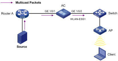
Multicast delivery to a wireless client (for the WX5540E)
Network requirements
As shown in Figure 7, the multicast source 1.1.1.1/24 sends multicast traffic to multicast group 224.1.1.1. The client is a member of the multicast group.
The client and the source can communicate with each other and the client can receive multicast traffic from the source.
Configuration procedure
1. Configure WLAN services:
# Configure WLAN-ESS 1 and assign WLAN ESS 1 to VLAN 100.
<AC>system-view
[AC]Vlan 100
[AC-vlan100]quit
[AC]interface WLAN-ESS 1
[AC-WLAN-ESS1]port access vlan 100
[AC-WLAN-ESS1]quit
# Configure a WLAN service template with its SSID set to multicast and authentication method set to open-system. Bind the WLAN-ESS interface with the service template.
[AC]wlan service-template 1 clear
[AC-wlan-st-1]ssid Multicast
[AC-wlan-st-1]bind WLAN-ESS 1
[AC-wlan-st-1]authentication-method open-system
[AC-wlan-st-1]service-template enable
[AC-wlan-st-1]quit
# Create AP template ap of model WA3628i-AGN and configure its serial ID as 210235A29G007C000020.
[AC]wlan ap ap model WA3628i-AGN
[AC-wlan-ap-ap]serial-id 210235A29G007C000020
# Configure the mapping between the service template and the current radio.
[AC-wlan-ap-ap]radio 1
[AC-wlan-ap-ap-radio-1]service-template 1
[AC-wlan-ap-ap-radio-1]radio enable
[AC-wlan-ap-ap-radio-1]quit
[AC-wlan-ap-ap]quit
2. Configure the wireless client to join the multicast group:
# Create VLAN 100, enable IGMP snooping, and specify IGMPv3 snooping in the VLAN.
<AC>system-view
[AC]igmp-snooping
[AC-igmp-snooping]quit
[AC]vlan 100
[AC-vlan100]igmp-snooping enable
[AC-vlan100]igmp-snooping version 3
[AC-vlan100]quit
# Configure the internal aggregate interface of the AC as a hybrid port and assign it to VLAN 100.
[AC]interface Bridge-Aggregation 1
[AC-Bridge-Aggregation1] port link-type hybrid
[AC-Bridge-Aggregation1] port hybrid vlan 100 tagged
[AC-Bridge-Aggregation1]quit
# Log into the configuration interface of the switching engine on the WX3024E and enable IGMP snooping globally.
<AC> oap connect slot 0
Press CTRL+K to quit.
Connected to OAP!
User interface aux0 is available.
Press ENTER to get started.
<Device> system-view
[Device] igmp-snooping
[Device-igmp-snooping] quit
# Create VLAN 100 and enable IGMP snooping in the VLAN. Configure GigabitEthernet 1/0/2 as a trunk port and assign it to the VLAN.
[Device] vlan 100
[Device-vlan100] igmp-snooping enable
[Device-vlan100] quit
[Device] interface GigabitEthernet 1/0/2
[Device-GigabitEthernet1/0/2] port link-type trunk
[Device-GigabitEthernet1/0/2] port trunk permit vlan 100
[Device-GigabitEthernet1/0/2] quit
# Configure the internal aggregate interface of the switching engine as a hybrid port and assign it to VLAN 100.
[Device] interface Bridge-Aggregation 1
[Device-Bridge-Aggregation1] port link-type hybrid
[Device-Bridge-Aggregation1] port hybrid vlan 100 tagged
[Device-Bridge-Aggregation1] quit
# Use the shortcut keys Ctrl + K to exit the switching engine configuration interface and return to the AC engine configuration interface.
# Configure the client to access the WLAN service and request multicast traffic destined for 224.1.1.1.
Verifying the configuration
# Display detailed IGMP snooping group information in VLAN 100 on the AC.
[AC]display igmp-snooping group vlan 100 verbose
Total 1 IP Group(s).
Total 1 IP Source(s).
Total 1 MAC Group(s).
Port flags: D-Dynamic port, S-Static port, C-Copy port, P-PIM port
Subvlan flags: R-Real VLAN, C-Copy VLAN
Port flags: D-Dynamic port, S-Static port, A-Aggregation port, C-Copy port, P-PIM port
Subvlan flags: R-Real VLAN, C-Copy VLAN
Vlan(id):100.
Total 1 IP Group(s).
Total 1 IP Source(s).
Total 1 MAC Group(s).
Router port(s):total 0 port(s).
IP group(s):the following ip group(s) match to one mac group.
IP group address:224.1.1.1
(0.0.0.0, 224.1.1.1):
Attribute: Host Port
Host port(s):total 1 port(s).
WLAN-DBSS1:0 (D) ( 00:04:17 )
MAC group(s):
MAC group address:0100-5e01-0101
Host port(s):total 1 port(s).
WLAN-DBSS1:0
The output shows that WLAN-DBSS 1:0 on the AC engine joins the multicast group 224.1.1.1.
Multicast delivery to a wireless client (for the WX3000E series)
Network requirements
As shown in Figure 8, the multicast source 1.1.1.1/24 sends multicast traffic to multicast group 224.1.1.1. The client is a member of the multicast group.
The client and the source can communicate with each other and the client can receive multicast traffic from the source.
Configuration procedure
1. Configure WLAN services:
# Configure WLAN-ESS 1 and assign WLAN ESS 1 to VLAN 100.
<AC>system-view
[AC]Vlan 100
[AC-vlan100]quit
[AC]interface WLAN-ESS 1
[AC-WLAN-ESS1]port access vlan 100
[AC-WLAN-ESS1]quit
# Configure a WLAN service template with its SSID set to multicast and authentication method set to open-system. Bind the WLAN-ESS interface with the service template.
[AC]wlan service-template 1 clear
[AC-wlan-st-1]ssid Multicast
[AC-wlan-st-1]bind WLAN-ESS 1
[AC-wlan-st-1]authentication-method open-system
[AC-wlan-st-1]service-template enable
[AC-wlan-st-1]quit
# Create AP template ap of model WA3628i-AGN and configure its serial ID as 210235A29G007C000020.
[AC]wlan ap ap model WA3628i-AGN
[AC-wlan-ap-ap]serial-id 210235A29G007C000020
# Configure the mapping between the service template and the current radio.
[AC-wlan-ap-ap]radio 1
[AC-wlan-ap-ap-radio-1]service-template 1
[AC-wlan-ap-ap-radio-1]radio enable
[AC-wlan-ap-ap-radio-1]quit
[AC-wlan-ap-ap]quit
2. Configure the wireless client to join the multicast group:
# Create VLAN 100, enable IGMP snooping, and specify IGMPv3 snooping in the VLAN.
<AC>system-view
[AC]igmp-snooping
[AC-igmp-snooping]quit
[AC]vlan 100
[AC-vlan100]igmp-snooping enable
[AC-vlan100]igmp-snooping version 3
[AC-vlan100]quit
# Configure the internal aggregate interface of the AC as a hybrid port and assign it to VLAN 100.
[AC]interface Bridge-Aggregation 1
[AC-Bridge-Aggregation1] port link-type hybrid
[AC-Bridge-Aggregation1] port hybrid vlan 100 tagged
[AC-Bridge-Aggregation1]quit
# Log into the configuration interface of the switching engine on the WX3024E and enable IGMP snooping globally.
<AC> oap connect slot 0
Press CTRL+K to quit.
Connected to OAP!
User interface aux0 is available.
Press ENTER to get started.
<Device> system-view
[Device] igmp-snooping
[Device-igmp-snooping] quit
# Create VLAN 100 and enable IGMP snooping in the VLAN. Configure GigabitEthernet 1/0/2 as a trunk port and assign it to the VLAN.
[Device] vlan 100
[Device-vlan100] igmp-snooping enable
[Device-vlan100] quit
[Device] interface GigabitEthernet 1/0/2
[Device-GigabitEthernet1/0/2] port link-type trunk
[Device-GigabitEthernet1/0/2] port trunk permit vlan 100
[Device-GigabitEthernet1/0/2] quit
# Configure the internal aggregate interface of the switching engine as a hybrid port and assign it to VLAN 100.
[Device] interface Bridge-Aggregation 1
[Device-Bridge-Aggregation1] port link-type hybrid
[Device-Bridge-Aggregation1] port hybrid vlan 100 tagged
[Device-Bridge-Aggregation1] quit
# Use the shortcut keys Ctrl + K to exit the switching engine configuration interface and return to the AC engine configuration interface.
# Configure the client to access the WLAN service and request multicast traffic destined for 224.1.1.1.
Verifying the configuration
# Display detailed IGMP snooping group information in VLAN 100 on the AC.
[AC]display igmp-snooping group vlan 100 verbose
Total 1 IP Group(s).
Total 1 IP Source(s).
Total 1 MAC Group(s).
Port flags: D-Dynamic port, S-Static port, A-Aggregation port, C-Copy port, P-PIM port
Subvlan flags: R-Real VLAN, C-Copy VLAN
Vlan(id):100.
Total 1 IP Group(s).
Total 1 IP Source(s).
Total 1 MAC Group(s).
Router port(s):total 0 port(s).
IP group(s):the following ip group(s) match to one mac group.
IP group address:224.1.1.1
(0.0.0.0, 224.1.1.1):
Attribute: Host Port
Host port(s):total 1 port(s).
WLAN-DBSS1:0 (D) ( 00:04:17 )
MAC group(s):
MAC group address:0100-5e01-0101
Host port(s):total 1 port(s).
WLAN-DBSS1:0
The output shows that WLAN-DBSS 1:0 on the AC engine joins the multicast group 224.1.1.1.
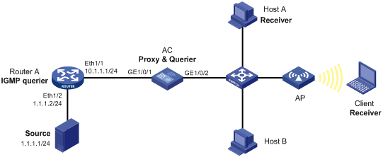
IGMP snooping proxying configuration example
Network requirements
As shown in Figure 9, Router A runs IGMPv2 and the AC runs IGMPv2 snooping. Router A serves as an IGMP querier.
Configure IGMP snooping proxying on the AC so that the AC can forward IGMP reports and leave messages on behalf of attached hosts, respond to IGMP queries from Router A, and forward the queries to the hosts on behalf of Router A.
Configuration procedure
1. Configure an IP address and subnet mask for each interface, as shown in Figure 9. (Details not shown.)
2. On Router A, enable IP multicast routing, enable IGMP on Ethernet 1/1, and enable PIM-DM on each interface.
<RouterA> system-view
[RouterA] multicast routing-enable
[RouterA] interface ethernet 1/1
[RouterA-Ethernet1/1] igmp enable
[RouterA-Ethernet1/1] pim dm
[RouterA-Ethernet1/1] quit
[RouterA] interface ethernet 1/2
[RouterA-Ethernet1/2] pim dm
[RouterA-Ethernet1/2] quit
3. Configure the AC:
# Enable IGMP snooping globally.
<AC> system-view
[AC] igmp-snooping
[AC-igmp-snooping] quit
# Create VLAN 100, assign ports GigabitEthernet 1/0/1 and GigabitEthernet 1/0/2 to this VLAN, and enable IGMP snooping and IGMP snooping proxying in the VLAN.
[AC] vlan 100
[AC-vlan100] port gigabitethernet 1/0/1 gigabitethernet 1/0/2
[AC-vlan100] igmp-snooping enable
[AC-vlan100] igmp-snooping proxying enable
[AC-vlan100] quit
# Configure WLAN ESS interface 1 and assign it to VLAN100.
[AC]interface WLAN-ESS 1
[AC-WLAN-ESS1]port access vlan 100
[AC-WLAN-ESS1]quit
# Configure a WLAN service template with its SSID as multicast and authentication method as open-system. Bind the WLAN-ESS interface with the service template.
[AC]wlan service-template 1 clear
[AC-wlan-st-1]ssid Multicast
[AC-wlan-st-1]bind WLAN-ESS 1
[AC-wlan-st-1]authentication-method open-system
[AC-wlan-st-1]service-template enable
[AC-wlan-st-1]quit
# Create AP template ap of model WA3628i-AGN and configure its serial ID as 210235A29G007C000020.
[AC]wlan ap ap model WA3628i-AGN
[AC-wlan-ap-ap]serial-id 210235A29G007C000020
# Configure the mapping between the service template and the current radio.
[AC-wlan-ap-ap]radio 1
[AC-wlan-ap-ap-radio-1]service-template 1
[AC-wlan-ap-ap-radio-1]radio enable
[AC-wlan-ap-ap-radio-1]quit
[AC-wlan-ap-ap]quit
Verifying the configuration
1. Verify that the AC and Router A create a forwarding entry for the multicast group 224.1.1.1 after Host A and the client join the group.
# Send IGMP reports from Host A and the client to join the group.(Details not shown.)
# Display information about IGMP snooping groups on the AC.
[AC] display igmp-snooping group
Total 1 IP Group(s).
Total 1 IP Source(s).
Total 1 MAC Group(s).
Port flags: D-Dynamic port, S-Static port, C-Copy port, P-PIM port
Subvlan flags: R-Real VLAN, C-Copy VLAN
Vlan(id):100.
Total 1 IP Group(s).
Total 1 IP Source(s).
Total 1 MAC Group(s).
Router port(s):total 1 port(s).
GE1/0/1 (D) ( 00:01:23 )
IP group(s):the following ip group(s) match to one mac group.
IP group address:224.1.1.1
(0.0.0.0, 224.1.1.1):
Host port(s):total 1 port(s).
WLAN-DBSS1:0 (D)
MAC group(s):
MAC group address:0100-5e01-0101
Host port(s):total 1 port(s).
WLAN-DBSS1:0
# Display information about IGMP multicast groups on Router A.
[RouterA] display igmp group
Total 1 IGMP Group(s).
Interface group report information of VPN-Instance: public net
Ethernet1/1(10.1.1.1):
Total 1 IGMP Group reported
Group Address Last Reporter Uptime Expires
224.1.1.1 0.0.0.0 00:00:06 00:02:04
2. Verify that the AC still maintains the forwarding entry for the multicast group 224.1.1.1 after Host A leaves the group.
# Send an IGMP leave message from Host A to leave the group. (Details not shown.)
# Display information about IGMP snooping groups on the AC.
[AC] display igmp-snooping group
Total 1 IP Group(s).
Total 1 IP Source(s).
Total 1 MAC Group(s).
Port flags: D-Dynamic port, S-Static port, C-Copy port, P-PIM port
Subvlan flags: R-Real VLAN, C-Copy VLAN
Vlan(id):100.
Total 1 IP Group(s).
Total 1 IP Source(s).
Total 1 MAC Group(s).
Router port(s):total 1 port(s).
GE1/0/1 (D) ( 00:01:23 )
IP group(s):the following ip group(s) match to one mac group.
IP group address:224.1.1.1
(0.0.0.0, 224.1.1.1):
Host port(s):total 1 port(s).
WLAN-DBSS1:0 (D)
MAC group(s):
MAC group address:0100-5e01-0101
Host port(s):total 1 port(s).
WLAN-DBSS1:0
Troubleshooting IGMP snooping
This section describes common IGMP snooping problems and how to troubleshoot them.
Layer 2 multicast forwarding cannot function
Symptom
Layer 2 multicast forwarding cannot function.
Analysis
IGMP snooping is not enabled.
Solution
1. Use the display current-configuration command to view the running status of IGMP snooping.
2. If IGMP snooping is not enabled, use the igmp-snooping command in system view to enable IGMP snooping globally, and then use the igmp-snooping enable command in VLAN view to enable IGMP snooping for the VLAN.
3. If IGMP snooping is enabled globally but not enabled for the VLAN, use the igmp-snooping enable command in VLAN view to enable IGMP snooping for the VLAN.
4. If the problem persists, contact H3C Support.
Configured multicast group policy fails to take effect
Symptom
Although a multicast group policy has been configured to allow hosts to join specific multicast groups, the hosts can still receive multicast data addressed to other multicast groups.
Analysis
· The ACL rule is incorrectly configured.
· The multicast group policy is not correctly applied.
· The function of dropping unknown multicast data is not enabled, so unknown multicast data is flooded.
· Certain ports have been configured as static member ports of a multicasts group, and this configuration conflicts with the configured multicast group policy.
Solution
1. Use the display acl command to check the configured ACL rule. Make sure the ACL rule conforms to the multicast group policy to be implemented.
2. Use the display this command in IGMP-snooping view or in the corresponding interface view to verify that the correct multicast group policy has been applied. If not, use the group-policy or igmp-snooping group-policy command to apply the correct multicast group policy.
3. Use the display current-configuration command to verify that the function of dropping unknown multicast data is enabled. If not, use the drop-unknown or igmp-snooping drop-unknown command to enable the function of dropping unknown multicast data.
4. Use the display igmp-snooping group command to verify that any port has been configured as a static member port of any multicast group. If so, check whether this configuration conflicts with the configured multicast group policy. If any conflict exists, remove the port as a static member of the multicast group.
5. If the problem persists, contact H3C Support.