- Table of Contents
-
- 12-Network Management and Monitoring
- 00-Preface
- 01-System maintenance and debugging configuration
- 02-NQA configuration
- 03-NTP configuration
- 04-SNMP configuration
- 05-RMON configuration
- 06-NETCONF configuration
- 07-EAA configuration
- 08-Process monitoring and maintenance configuration
- 09-PoE configuration
- 10-Flow log configuration
- 11-Packet capture configuration
- 12-Information center configuration
- 13-Mirroring configuration
- Related Documents
-
| Title | Size | Download |
|---|---|---|
| 09-PoE configuration | 115.87 KB |
Contents
Feature and hardware compatibility
Enabling nonstandard PD detection
Configuring PI power management
Configuring PSE power monitoring
Enabling PoE over-temperature protection
Configuring a PI by using a PoE profile
Upgrading PSE firmware in service
Displaying and maintaining PoE
Failure to set the priority of a PI to critical
Failure to apply a PoE profile to a PI
Configuring PoE
Overview
IEEE 802.3af-compliant power over Ethernet (PoE) enables a network device to supply power to terminals over twisted pair cables.
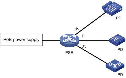
As shown in Figure 1, a PoE system includes the following elements:
· PoE power supply—The PoE power supply provides power for the entire PoE system.
· PSE—A power sourcing equipment (PSE) detects and classifies powered devices (PDs), supplies power to PDs, and monitors the PD power and connection status. PSEs include endpoint PSEs and midspan PSEs. H3C PSEs are endpoint PSEs.
· PI—A power interface (PI) is a PoE-capable Ethernet interface on a PSE.
· PD—A PD receives power from the PSE.
PDs include IP telephones, APs, portable chargers, POS terminals, and Web cameras.
You can also connect a PD to a redundant power source for reliability.
Feature and hardware compatibility
|
Hardware series |
Model |
PoE compatibility |
|
WX1800H series |
WX1804H WX1810H WX1820H |
No |
|
WX2500H series |
WX2510H |
Yes |
|
WX2540H |
No |
|
|
WX2560H |
No |
|
|
WX3000H series |
WX3010H WX3010H-L WX3010H-X WX3024H WX3024H-L |
Yes |
|
WX3500H series |
WX3508H WX3510H WX3520H WX3540H |
No |
|
WX5500E series |
WX5510E WX5540E |
No |
|
WX5500H series |
WX5540H WX5560H WX5580H |
No |
|
Access controller modules |
EWPXM1MAC0F EWPXM1WCME0 EWPXM2WCMD0F LSQM1WCMX20 LSQM1WCMX40 LSUM1WCME0 LSUM1WCMX20RT LSUM1WCMX40RT |
No |
PoE configuration task list
You can configure a PI directly on the port or by configuring a PoE profile and applying the PoE profile to the PI. To configure one PI, configure it on the port. To configure multiple PIs in batches, use the PoE profile.
Before configuring PoE, make sure the PoE power supply and PSE are operating correctly. Otherwise, either you cannot configure PoE or the PoE configuration cannot take effect.
To configure PoE, perform the following tasks:
|
Tasks at a glance |
|
(Required.) Enabling PoE for a PI |
|
(Optional.) Enabling nonstandard PD detection |
|
(Optional.) Configuring PI power management |
|
(Optional.) Configuring the PoE monitoring function: |
|
(Optional.) Configuring a PI by using a PoE profile: |
|
(Optional.) Upgrading PSE firmware in service |
Enabling PoE for a PI
The system only supplies power to and reserves power for PDs connected to PoE-enabled PIs.
You can enable PoE for a PI if the PI will not result in PSE power overload.
If the PI will result in PSE power overload, you can enable PoE for the PI only when PI power management is enabled. For more information about PI power management, see "Configuring PI power management."
The PSE supplies power over the Category 3 or Category 5 twisted pair cable connected to a PI in the following modes:
· Over signal wires—The PSE uses data pairs (pins 1, 2, 3, and 6) to supply DC power to PDs.
· Over spare wires—The PSE uses spare pairs (pins 4, 5, 7, and 8) to supply DC power to PDs.
|
|
NOTE: · The device supports power transmission only over signal wires. · The power transmission mode varies by device model. For more information, see Network Management and Monitoring Command Reference. A PSE can supply power to a PD directly only when the PSE and PD use the same power transmission mode. If the PSE and PD use different power transmission modes, you must change the order of the lines in the twisted pair cable to supply power to the PD. |
To enable PoE for a PI:
|
Step |
Command |
Remarks |
|
1. Enter system view. |
system-view |
N/A |
|
2. Enter PI view. |
interface interface-type interface-number |
N/A |
|
3. Enable PoE for the PI. |
poe enable |
By default, PoE is disabled for a PI. |
|
4. (Optional.) Configure power transmission mode. |
poe mode { signal | spare } |
The default mode is power over signal cables (signal). |
|
5. (Optional.) Configure a description for the PD connected to the PI. |
poe pd-description text |
By default, no description is configured for the PD connected to the PI. |
Enabling nonstandard PD detection
|
Step |
Command |
Remarks |
|
1. Enter system view. |
system-view |
N/A |
|
2. Enable nonstandard PD detection. |
poe legacy enable |
By default, nonstandard PD detection is disabled. The PSE detects only IEEE 802.3af-compliant standard PDs and supplies power to them. |
Configuring PI power management
The following matrix shows the feature and hardware compatibility:
|
Hardware series |
Model |
PI power management compatibility |
|
WX1800H series |
WX1804H WX1810H WX1820H |
No |
|
WX2500H series |
WX2510H WX2540H WX2560H |
No |
|
WX3000H series |
WX3010H WX3010H-L WX3010H-X WX3024H WX3024H-L |
Yes |
|
WX3500H series |
WX3508H WX3510H WX3520H WX3540H |
No |
|
WX5500E series |
WX5510E WX5540E |
No |
|
WX5500H series |
WX5540H WX5560H WX5580H |
No |
|
Access controller modules |
EWPXM1MAC0F EWPXM1WCME0 EWPXM2WCMD0F LSQM1WCMX20 LSQM1WCMX40 LSUM1WCME0 LSUM1WCMX20RT LSUM1WCMX40RT |
No |
PI power management enables the PSE to perform priority-based PI power management in PSE power overload situations. The power-supply priority levels of a PI are critical, high, and low in descending order. The PD priority is determined by the priority of the PI to which the PD is connected. All PSEs use the same PI power management mechanism.
If you do not enable PI power management, the PSE performs operations based on the status of the maximum PSE power upon power overload:
|
Maximum PSE power |
PSE operations |
|
Configured |
The PSE stops power supply to the new PD. |
|
Not configured |
The PSE stops power supply to all PDs when the PoE self-protection mechanism is triggered. |
If you enable PI power management, the PSE stops power supply to existing PDs causing overload or performs priority-based operations for new PDs causing overload:
|
Priority of the new PD |
PSE operations |
|
Low |
The PSE does not supply power to a new PD. |
|
High |
· If low-priority PDs exist, the PSE stops power supply to the existing low-priority PDs, and supplies power to the new PD. · If no low-priority PDs exist, the PSE does not supply power to the new PD. |
|
Critical |
· If low-priority or high-priority PDs exist, the PSE stops power supply to the existing low-priority or high-priority PDs, and supplies power to the new PD. · If no low-priority or high-priority PDs exist, the PSE does not supply power to the new PD. |
|
|
NOTE: Configuration for PIs whose power is preempted remains unchanged. |
If multiple new PDs require power supply, the PSE supplies power to PDs in priority descending order. For PDs with the same priority, the one with the smallest PD ID takes precedence.
If multiple existing PDs need to be stopped with power supply, the PSE stops power supply to PDs in priority ascending order. For PDs with the same priority, the one with the greatest ID takes precedence.
The PSE guarantees its critical PIs uninterruptable power by reserving guaranteed PSE power. If you want a PI to be allocated with uninterruptable power, configure the PI with critical priority. Otherwise, configure the PI with high or low priority to ensure that other PIs can be supplied with power.
Before you configure a PI with critical priority, make sure the remaining guaranteed power is greater than or equal to the maximum power of the PI. The remaining guaranteed PSE power is the maximum PSE power minus the maximum power for PoE-enabled and PoE-disabled critical PIs.
To configure PI power management:
|
Step |
Command |
Remarks |
|
1. Enter system view. |
system-view |
N/A |
|
2. Enable PI power management. |
poe pd-policy priority |
By default, PI power management is disabled. |
|
3. Enter PI view. |
interface interface-type interface-number |
N/A |
|
4. (Optional.) Configure the power supply priority for a PI. |
poe priority { critical | high | low } |
By default, the power supply priority for the PSE is low. |
Configuring PoE monitoring
When the PoE monitoring function is enabled, the system monitors PSEs, PDs, and device temperature in real time. If a specific value exceeds the threshold, the system automatically takes self-protection measures.
If a PSE starts or stops power supply to a PD, the system automatically sends a notification message. For more information, see "Configuring SNMP."
Configuring PSE power monitoring
The system monitors PSE power utilization and sends notification messages when PSE power utilization exceeds or drops below the threshold. If PSE power utilization crosses the threshold multiple times in succession, the system sends notification messages only for the first crossing. For more information about the notification message, see "Configuring SNMP."
To configure a PSE power alarm threshold:
|
Step |
Command |
Remarks |
|
1. Enter system view. |
system-view |
N/A |
|
2. Configure a power alarm threshold for the PSE. |
poe utilization-threshold utilization-threshold-value |
By default, the power alarm threshold for the PSE is 80%. |
Enabling PoE over-temperature protection
The following matrix shows the feature and hardware compatibility:
|
Hardware series |
Model |
PoE over-temperature protection compatibility |
|
WX1800H series |
WX1804H WX1810H WX1820H |
No |
|
WX2500H series |
WX2510H WX2540H WX2560H |
No |
|
WX3000H series |
WX3010H WX3010H-L WX3010H-X WX3024H WX3024H-L |
Yes |
|
WX3500H series |
WX3508H WX3510H WX3520H WX3540H |
No |
|
WX5500E series |
WX5510E WX5540E |
No |
|
WX5500H series |
WX5540H WX5560H WX5580H |
No |
|
Access controller modules |
EWPXM1MAC0F EWPXM1WCME0 EWPXM2WCMD0F LSQM1WCMX20 LSQM1WCMX40 LSUM1WCME0 LSUM1WCMX20RT LSUM1WCMX40RT |
No |
The PoE over-temperature protection enables the system to monitor the chassis internal temperature in real time. When the temperature exceeds the upper limit, the system disables PoE for all PIs. When the temperature drops below the lower limit, the system re-enables PoE on all PIs. The upper and lower temperature limits depend on hardware specifications and are not configurable at the CLI.
To enable PoE over-temperature protection:
|
Step |
Command |
Remarks |
|
1. Enter system view. |
system-view |
N/A |
|
2. Enable PoE over-temperature protection. |
poe temperature-protection enable |
By default, PoE over-temperature protection is enabled. |
Configuring a PI by using a PoE profile
A PoE profile is a collection of configurations that contain multiple PoE features.
You can configure a PI either on the port or by using a PoE profile. If you configure a parameter twice with different methods, only the first configuration takes effect.
The PoE profile is preferable for PI configuration in batches and PD-specific PI configuration.
· You can apply a PoE profile to multiple PIs. PIs configured by the same PoE profile have the same PoE features.
· You can define PoE configurations for a PD in a PoE profile, and apply the PoE profile to the PI to which the PD connects. This avoids reconfiguration when the PD is moved to another PI.
Configuring a PoE profile
|
Step |
Command |
Remarks |
|
1. Enter system view. |
system-view |
N/A |
|
2. Create a PoE profile, and enter PoE profile view. |
poe-profile profile-name [ index ] |
By default, no PoE profiles exist. |
|
3. Enable PoE. |
poe enable |
By default, this function is disabled. |
|
4. (Optional.) Configure PoE power transmission mode. |
poe mode { signal | spare } |
The default mode is power over signal pins (signal). |
|
5. (Optional.) Configure PI priority. |
poe priority { critical | high | low } |
The default priority is low. |
Applying a PoE profile
You can apply a PoE profile in system view or PI view. If you perform the operation in both views, the most recent operation takes effect. To apply a PoE profile to multiple PIs, perform the operation in system view. A PoE profile can be applied to multiple PIs, but a PI can have only one PoE profile.
To modify an applied PoE profile, first execute the undo apply poe-profile or undo apply poe-profile interface command to remove its application.
Applying a PoE profile to multiple PIs in system view
|
Step |
Command |
Remarks |
|
1. Enter system view. |
system-view |
N/A |
|
2. Apply a PoE profile to one or multiple PIs. |
apply poe-profile { index index | name profile-name } interface interface-range |
By default, no PoE profile is applied to a PI. |
Applying a PoE profile to a PI in PI view
|
Step |
Command |
Remarks |
|
1. Enter system view. |
system-view |
N/A |
|
2. Enter PI view. |
interface interface-type interface-number |
N/A |
|
3. Apply the PoE profile to the interface. |
apply poe-profile { index index | name profile-name } |
By default, no PoE profile is applied to a PI. |
Upgrading PSE firmware in service
The following matrix shows the feature and hardware compatibility:
|
Hardware series |
Model |
PSE firmware in-service upgrade compatibility |
|
WX1800H series |
WX1804H WX1810H WX1820H |
No |
|
WX2500H series |
WX2510H WX2540H WX2560H |
No |
|
WX3000H series |
WX3010H WX3010H-L WX3010H-X WX3024H WX3024H-L |
Yes |
|
WX3500H series |
WX3508H WX3510H WX3520H WX3540H |
No |
|
WX5500E series |
WX5510E WX5540E |
No |
|
WX5500H series |
WX5540H WX5560H WX5580H |
No |
|
Access controller modules |
EWPXM1MAC0F EWPXM1WCME0 EWPXM2WCMD0F LSQM1WCMX20 LSQM1WCMX40 LSUM1WCME0 LSUM1WCMX20RT LSUM1WCMX40RT |
No |
You can upgrade the PSE firmware in service in either of the following modes:
· Refresh mode—Updates the PSE firmware without deleting it. You can use the refresh mode in most cases.
· Full mode—Deletes the current PSE firmware and reloads a new one. Use the full mode if the PSE firmware is damaged and you cannot execute any PoE commands.
If the PSE firmware upgrade fails because of interruption such as a device reboot, you can restart the device and upgrade it in full mode again. After the upgrade, restart the device manually for the new PSE firmware to take effect.
To upgrade the PSE firmware in service:
|
Step |
Command |
|
1. Enter system view. |
system-view |
|
2. Upgrade the PSE firmware in service. |
poe update { full | refresh } filename |
Displaying and maintaining PoE
Execute display commands in any view.
|
Task |
Command |
|
Display general PSE information. |
display poe device |
|
Display the power supplying information for the specified PI. |
display poe interface [ interface-type interface-number ] |
|
Display power information for PIs. |
display poe interface power [ interface-type interface-number ] |
|
Display detailed PSE information. |
display poe pse |
|
Display the power supplying information for all PIs on a PSE. |
display poe interface |
|
Display power information for all PIs on a PSE. |
display poe interface power |
|
Display all information about the PoE profile. |
display poe-profile [ index index | name profile-name ] |
|
Display all information about the PoE profile applied to the specified PI. |
display poe-profile interface interface-type interface-number |
PoE configuration example
Network requirements
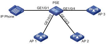
As shown in Figure 2, configure PoE to meet the following requirements:
· Enable the device to supply power to IP telephones and APs.
· Enable the device to supply power to IP telephones first when overload occurs.
Configuration procedure
# Enable PoE on GigabitEthernet 1/0/1, GigabitEthernet 1/0/2, GigabitEthernet 1/0/3, and GigabitEthernet1/0/4, and set the power supply priority to critical for GigabitEthernet 1/0/1.
[PSE] interface gigabitethernet 1/0/1
[PSE-GigabitEthernet1/0/1] poe enable
[PSE-GigabitEthernet1/0/1] poe priority critical
[PSE-GigabitEthernet1/0/1] quit
[PSE] interface gigabitethernet 1/0/2
[PSE-GigabitEthernet1/0/2] poe enable
[PSE-GigabitEthernet1/0/2] quit
[PSE] interface gigabitethernet 1/0/3
[PSE-GigabitEthernet1/0/3] poe enable
[PSE-GigabitEthernet1/0/3] quit
[PSE] interface gigabitethernet 1/0/4
[PSE-GigabitEthernet1/0/4] poe enable
[PSE-GigabitEthernet1/0/4] quit
Verifying the configuration
# Connect the IP telephones and APs to the PSE to verify that they can obtain power and operate correctly. (Details not shown.)
Troubleshooting PoE
Failure to set the priority of a PI to critical
Symptom
Power supply priority configuration for a PI failed.
Solution
To resolve the problem:
1. Identify whether the priority has been configured through other methods. If the priority has been configured, remove the configuration.
2. If the problem persists, contact H3C Support.
Failure to apply a PoE profile to a PI
Symptom
PoE profile application for a PI failed.
Solution
To resolve the problem:
1. Identify whether some settings in the PoE profile have been configured. If they have been configured, remove the configuration.
2. Identify whether the settings in the PoE profile meet the requirements of the PI. If they do not, modify the settings in the PoE profile.
3. Identify whether another PoE profile is already applied to the PI. If it is, remove the application.
4. If the problem persists, contact H3C Support.