- Table of Contents
- Related Documents
-
| Title | Size | Download |
|---|---|---|
| 06-Web configuration examples | 1.56 MB |
Contents
System features configuration examples
Network settings configuration examples
Intra-AC roaming configuration example
Inter-AC roaming configuration example
Layer 2 static aggregation configuration example
Layer 2 dynamic aggregation configuration example
MAC address table configuration example
Outbound dynamic NAT configuration example
NAT Server for external-to-internal access configuration example
Static NAT 444 configuration example
Dynamic NAT 444 configuration example
IPv4 static route configuration example
IPv6 static route configuration example
Static IPv6 address configuration example
DHCP server configuration example
DHCP relay agent configuration example
DHCP snooping configuration example
IPv4 static DNS configuration example
IPv4 dynamic DNS configuration example
IPv4 DNS proxy configuration example
IPv6 static DNS configuration example
IPv6 dynamic DNS configuration example
IPv6 DNS proxy configuration example
IGMP snooping configuration example
MLD snooping configuration example
Proxy ARP configuration example
ARP attack protection configuration example
Using the device as the Stelnet server for password authentication configuration example
Network security configuration examples
ACL-based packet filter configuration example
Administrators configuration example
Network configuration examples
Wireless configuration examples
CAPWAP tunnel establishment through DHCP configuration example
CAPWAP tunnel establishment through DNS configuration example
AP group configuration example
Radio management configuration example
WIPS device classification and countermeasures configuration example
WIPS malformed packet and flood attack detection configuration example
Signature-based attack detection configuration example
Client rate limiting configuration example
Bandwidth guaranteeing configuration example
Shared key authentication configuration example
PSK authentication and bypass authentication configuration example
PSK authentication and MAC authentication configuration example
802.1X RADIUS authentication configuration example
802.1X local authentication configuration example
802.1X AKM configuration example
Direct portal authentication configuration example
WLAN RRM DFS configuration example
WLAN RRM TPC configuration example
Session-mode load balancing configuration example for radios
Traffic-mode load balancing configuration example for radios
Bandwidth-mode load balancing configuration example for radios
Session-mode load balancing configuration example for a load balancing group
Traffic-mode load balancing configuration example for a load balancing group
Bandwidth-mode load balancing configuration example for a load balancing group
Band navigation configuration example
Wireless locating configuration example
Network security configuration examples
Guest management configuration example
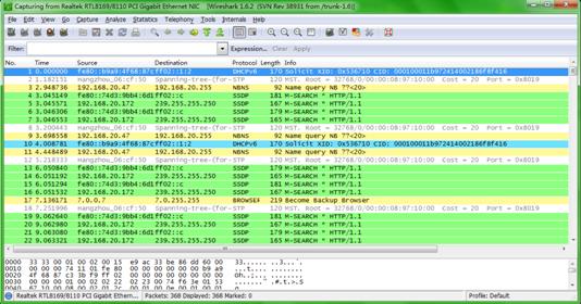
Local packet capture configuration example
Remote packet capture configuration example
System features configuration examples
Network settings configuration examples
Intra-AC roaming configuration example
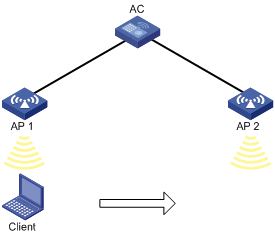
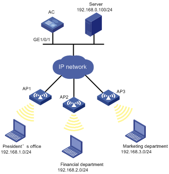
Network requirements
As shown in Figure 1, configure intra-AC roaming to enable the client to roam from AP 1 to AP 2. The two APs are managed by the same AC.
Configuration procedures
1. Click the network view tab at the bottom of the page.
2. Configure a wireless service:
a. From the navigation tree, select Wireless Configuration > Wireless Networks.
b. Add a wireless service:
- Create a wireless service named service.
- Set the SSID to roaming.
- Enable the wireless service.
3. Configure the APs:
a. From the navigation tree, select AP Management. You are placed on the AP tab.
b. Configure AP 1:
- Click the edit icon in the operation column for AP 1.
- Click the SSID setting tab, and bind the wireless service service to the radio of AP 1.
c. Configure AP 2 in the same way AP 1 is configured.
Verifying the configuration
# On the System View> Network Configuration > Mobility Domain > Roaming page, verify that the client associates with AP 1 before roaming and associates with AP 2 after roaming.
Inter-AC roaming configuration example
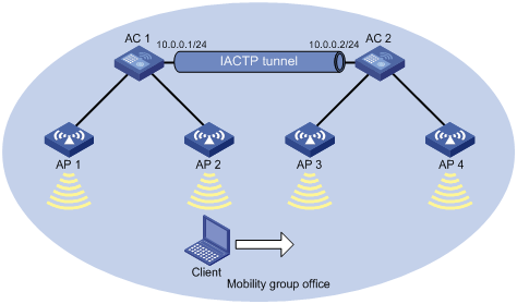
Network requirements
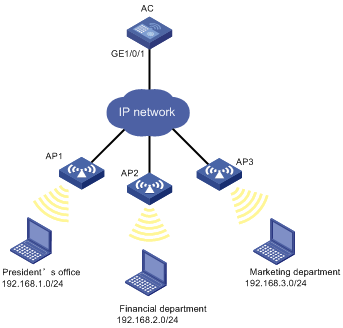
As shown in Figure 2, configure inter-AC roaming to enable the client to roam from AP 2 to AP 3 that are managed by different ACs.
Configuring AC 1
1. Click the network view tab at the bottom of the page.
2. Configure a wireless service:
a. From the navigation tree, select Wireless Configuration > Wireless Networks.
b. Add a wireless service:
- Create a wireless service named service.
- Set the SSID to roaming.
- Enable the wireless service.
3. Configure the APs:
a. From the navigation tree, select AP Management. You are placed on the AP tab.
b. Configure AP 1:
- Click the edit icon in the operation column for AP 1.
- Click the SSID setting tab, and bind the wireless service service to the radio of AP 1.
c. Configure AP 2 in the same way AP 1 is configured.
4. Click the system view tab at the bottom of the page.
5. Configure a mobility group:
a. From the navigation tree, select Network Configuration > Mobility Domain.
b. On the Roaming tab, perform the following tasks:
- Create a mobility group named office.
- Set the IP address type to IPv4 for IACTP tunnels.
- Specify 10.0.0.1 as the source IP address for establishing IACTP tunnels.
- Add the member device whose IP address is 10.0.0.2 to the mobility group.
- Enable the mobility group.
Configuring AC 2
1. Click the network view tab at the bottom of the page.
2. Configure a wireless service:
a. From the navigation tree, select Wireless Configuration > Wireless Networks.
b. Add a wireless service:
- Create a wireless service named service.
- Set the SSID to roaming.
- Enable the wireless service.
3. Configure the APs:
a. From the navigation tree, select AP Management. You are placed on the AP tab.
b. Configure AP 3:
- Click the edit icon in the operation column for AP 3.
- Click the SSID setting tab, and bind the wireless service service to the radio of AP 3.
c. Configure AP 4 in the same way AP 3 is configured.
4. Click the system view tab at the bottom of the page.
5. Configure a mobility group:
a. From the navigation tree, select Network Configuration > Mobility Domain.
b. On the Roaming tab, perform the following tasks:
- Create a mobility group named office.
- Set the IP address type to IPv4 for IACTP tunnels.
- Specify 10.0.0.2 as the source IP address for establishing IACTP tunnels.
- Add the member device whose IP address is 10.0.0.1 to the mobility group.
- Enable the mobility group.
Verifying the configuration
# On the System View> Network Configuration > Mobility Domain > Roaming page, verify the following information:
· The client associates with AP 2 managed by AC 1 before roaming.
· The client associates with AP 3 managed by AC 2 after roaming.
Layer 2 static aggregation configuration example
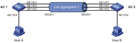
Network requirements
As shown in Figure 3, configure a Layer 2 static aggregation group on both AC 1 and AC 2 to improve the link reliability.
Configuration procedure
1. Configure Ethernet link aggregation on AC 1:
a. Click the system view tab at the bottom of the page.
b. From the navigation tree, select Network Configuration > Network Interfaces.
c. Click the Link Aggregation tab.
d. Configure a Layer 2 aggregation group:
- Add Layer 2 aggregation group 10.
- Configure the aggregation mode as Static.
- Assign ports GigabitEthernet 1/0/1 through GigabitEthernet 1/0/3 to the aggregation group.
2. Configure a VLAN on AC 1:
a. Click the system view tab at the bottom of the page.
b. From the navigation tree, select Network Configuration > VLAN. You are placed on the VLAN tab.
c. Create VLAN 10.
d. Access the details page for VLAN 10 to perform the following tasks:
- Add the port GigabitEthernet 1/0/4 (that connects to Host A) to the untagged port list.
- Add ports GigabitEthernet 1/0/1 through GigabitEthernet 1/0/3 to the tagged port list.
3. Configure AC 2 in the same way AC 1 is configured. (Details not shown.)
Verifying the configuration
1. Access the link aggregation page, and verify that ports GigabitEthernet 1/0/1 through GigabitEthernet 1/0/3 have been assigned to link aggregation group 10.
2. Verify that Host A can ping Host B.
3. Verify that Host A can still ping Host B after a link between AC 1 and AC 2 fails.
Layer 2 dynamic aggregation configuration example
Network requirements
As shown in Figure 4, configure a dynamic Layer 2 aggregation group on both AC 1 and AC 2 to improve the link reliability.
Configuration procedure
1. Configure Ethernet link aggregation on AC 1:
a. Click the system view tab at the bottom of the page.
b. From the navigation tree, select Network Configuration > Network Interfaces.
c. Click the Link Aggregation tab.
d. Configure a Layer 2 aggregation group:
- Add Layer 2 aggregation group 10.
- Configure the aggregation mode as Dynamic.
- Assign ports GigabitEthernet 1/0/1 through GigabitEthernet 1/0/3 to the aggregation group.
2. Configure a VLAN on AC 1:
a. Click the system view tab at the bottom of the page.
b. From the navigation tree, select Network Configuration > VLAN. You are placed on the VLAN tab.
c. Create VLAN 10.
d. Access the details page for VLAN 10 to perform the following tasks:
- Add the port GigabitEthernet 1/0/4 (that connects to Host A) to the untagged port list.
- Add ports GigabitEthernet 1/0/1 through GigabitEthernet 1/0/3 to the tagged port list.
3. Configure AC 2 in the same way AC 1 is configured. (Details not shown.)
Verifying the configuration
1. Access the link aggregation page, and verify that ports GigabitEthernet 1/0/1 through GigabitEthernet 1/0/3 have been assigned to link aggregation group 10.
2. Verify that Host A can ping Host B.
3. Verify that Host A can still ping Host B after a link between AC 1 and AC 2 fails.
MAC address table configuration example
Network requirements
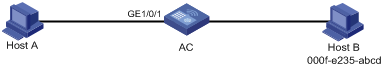
As shown in Figure 5:
· Host A at MAC address 000f-e235-dc71 is connected to interface GigabitEthernet 1/0/1 of the AC and belongs to VLAN 1.
· Host B at MAC address 000f-e235-abcd, which behaved suspiciously on the network, also belongs to VLAN 1.
Configure the MAC address table as follows:
· To prevent MAC address spoofing, add a static entry for Host A in the MAC address table of the AC.
· To drop all frames destined for Host B, add a blackhole MAC address entry for Host B.
· Set the aging timer to 500 seconds for dynamic MAC address entries.
Configuration procedures
1. Click the system view tab at the bottom of the page.
2. From the navigation tree, select Network Configuration > VLAN.
3. Click the MAC tab.
4. Add a static MAC address entry for MAC address 000f-e235-dc71 on GigabitEthernet 1/0/1 that belongs to VLAN 1.
5. Add a blackhole MAC address entry for MAC address 000f-e235-abcd that belongs to VLAN 1.
6. Access the advanced settings page to set the aging timer to 500 seconds for dynamic MAC address entries.
Verifying the configuration
# Access the Network Configuration > VLAN > MAC page to verify that a static and a blackhole MAC address entries have been created.
# Verify that Host B cannot ping Host A successfully.
MSTP configuration example
Network requirements
As shown in Figure 6, all devices in the network are in the same MST region. Device A and Device B operate at the distribution layer. Device C and the AC operate at the access layer.
Configure MSTP so that packets from different VLANs are forwarded along different spanning trees.
· Packets from VLAN 10 are forwarded along MSTI 1.
· Packets from VLAN 30 are forwarded along MSTI 2.

Configuration procedure
1. Configure VLANs:
a. Configure VLANs on Device A:
- Click the system view tab at the bottom of the page.
- From the navigation tree, select Network Configuration > VLAN. You are placed on the VLAN tab.
- Create VLAN 10 and VLAN 30.
- Access the details page for VLAN 10. Add ports GigabitEthernet 1/0/1 and GigabitEthernet 1/0/3 to the tagged port list.
- Access the details page for VLAN 30. Add ports GigabitEthernet 1/0/2 and GigabitEthernet 1/0/3 to the tagged port list.
b. Configure VLANs on Device B:
- Click the system view tab at the bottom of the page.
- From the navigation tree, select Network Configuration > VLAN. You are placed on the VLAN tab.
- Create VLAN 10 and VLAN 30.
- Access the details page for VLAN 10. Add ports GigabitEthernet 1/0/2 and GigabitEthernet 1/0/3 to the tagged port list.
- Access the details page for VLAN 30. Add ports GigabitEthernet 1/0/1 and GigabitEthernet 1/0/3 to the tagged port list.
c. Configure VLANs on the AC:
- Click the system view tab at the bottom of the page.
- From the navigation tree, select Network Configuration > VLAN. You are placed on the VLAN tab.
- Create VLAN 10.
- Access the details page for VLAN 10. Add ports GigabitEthernet 1/0/1 and GigabitEthernet 1/0/2 to the tagged port list.
d. Configure VLANs on Device C:
- Click the system view tab at the bottom of the page.
- From the navigation tree, select Network Configuration > VLAN. You are placed on the VLAN tab.
- Create VLAN 30.
- Access the details page for VLAN 30. Add ports GigabitEthernet 1/0/1 and GigabitEthernet 1/0/2 to the tagged port list.
2. Configure MSTP on Device A, Device B, Device C, and the AC:
a. Click the system view tab at the bottom of the page.
b. From the navigation tree, select Network Configuration > VLAN.
c. Click the STP tab.
d. Enable STP, and configure the operating mode as MSTP.
e. Access the MST region configuration page to perform the following tasks:
- Configure the MST region name as Web.
- Map VLAN 10 and VLAN 30 to MSTI 1 and MSTI 2, respectively.
- Set the MSTP revision level to 0.
Verifying the configuration
# Verify that the port roles and port states in the spanning tree status are as expected.
Outbound dynamic NAT configuration example
|
Hardware series |
Model |
Configuration example compatibility |
|
WX2500H series |
WX2510H WX2510H-F WX2540H WX2540H-F WX2560H |
Yes |
|
WX3000H series |
WX3010H WX3010H-X WX3010H-L WX3024H WX3024H-L WX3024H-F |
Yes: · WX3010H · WX3010H-X · WX3024H · WX3024H-F No: · WX3010H-L · WX3024H-L |
|
WX3500H series |
WX3510H WX3520H WX3520H-F WX3540H |
Yes |
|
WX5000 series |
WX5510E |
Yes |
|
WX5500 series |
WX5540E WX5540H WX5560H WX5580H |
Yes |
|
Access controller modules |
LSUM1WCME0 EWPXM1WCME0 LSQM1WCMX20 LSUM1WCMX20RT LSQM1WCMX40 LSUM1WCMX40RT EWPXM2WCMD0F EWPXM1MAC0F |
Yes |
Network requirements
As shown in Figure 7, a company has a private address 192.168.0.0/16 and two public IP addresses 202.38.1.2 and 202.38.1.3. Configure outbound dynamic NAT to allow only internal users on subnet 192.168.1.0/24 to access the Internet.

Configuration procedures
1. Click the system view tab at the bottom of the page.
2. From the navigation tree, select Network Configuration > Network Services >NAT.
3. Click Dynamic NAT.
4. Click the add icon.
5. On the New Dynamic NAT Rule page, perform the following tasks:
a. Add ACL 2000 to permit packets only from subnet 192.168.1.0/24 to pass through.
b. Add address group 0, and add an address range from 202.38.1.2 to 202.38.1.3 to the group.
6. Apply the dynamic NAT rule to VLAN-interface 20.
Verifying the configuration
# Verify that Client A can access the WWW server, but Client B cannot. (Details not shown.)
NAT Server for external-to-internal access configuration example
|
Hardware series |
Model |
Configuration example compatibility |
|
WX2500H series |
WX2510H WX2510H-F WX2540H WX2540H-F WX2560H |
Yes |
|
WX3000H series |
WX3010H WX3010H-X WX3010H-L WX3024H WX3024H-L WX3024H-F |
Yes: · WX3010H · WX3010H-X · WX3024H · WX3024H-F No: · WX3010H-L · WX3024H-L |
|
WX3500H series |
WX3510H WX3520H WX3520H-F WX3540H |
Yes |
|
WX5000 series |
WX5510E |
Yes |
|
WX5500 series |
WX5540E WX5540H WX5560H WX5580H |
Yes |
|
Access controller module |
LSUM1WCME0 EWPXM1WCME0 LSQM1WCMX20 LSUM1WCMX20RT LSQM1WCMX40 LSUM1WCMX40RT EWPXM2WCMD0F EWPXM1MAC0F |
Yes |
Network requirements
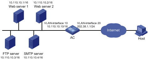
As shown in Figure 8, two Web servers, one FTP server and one SMTP server are in the internal network to provide services for external users. The internal network address is 10.110.0.0/16. The company has three public IP addresses from 202.38.1.1/24 to 202.38.1.3/24.
Configure the NAT Server feature to allow the external user to access the internal servers with public address 202.38.1.1/24.
Configuration procedures
1. Click the system view tab at the bottom of the page.
2. From the navigation tree, select Network Configuration > Network Services >NAT.
3. Click NAT Server.
4. Add the following servers:
# FTP server:
a. Click the add icon.
The New NAT Server page opens.
b. Select TCP from the IP protocol list.
c. Select a single public address with a single or no public port from the mapping type list.
d. Select Specify an IP address, set the address to 202.38.1.1, and set the port number to 21.
e. Set the IP address and port number for the internal server to 10.110.10.3 and 21, respectively.
f. Click Apply.
# Web server 1:
a. Click the add icon.
The New NAT Server page opens.
b. Select TCP from the IP protocol list.
c. Select a single public address with a single or no public port from the mapping type list.
d. Select Specify an IP address, set the address to 202.38.1.1, and set the port number to 80.
e. Set the IP address and port number for the internal server to 10.110.10.2 and 80, respectively.
f. Click Apply.
# Web server 2:
a. Click the add icon.
The New NAT Server page opens.
b. Select TCP from the IP protocol list.
c. Select a single public address with a single or no public port from the mapping type list.
d. Select Specify an IP address, set the address to 202.38.1.1, and set the port number to 80.
e. Set the IP address and port number for the internal server to 10.110.10.2 and 80, respectively.
f. Click Apply.
# SMTP server:
a. Click the add icon.
The New NAT Server page opens.
b. Select TCP from the IP protocol list.
c. Select a single public address with a single or no public port from the mapping type list.
d. Select Specify an IP address, set the address to 202.38.1.1, and set the port number to 25.
e. Set the IP address and port number for the internal server to 10.110.10.4 and 25, respectively.
f. Click Apply.
Verifying the configuration
# Verify that the host on the external network can access the internal servers by using the public addresses. (Details not shown.)
Static NAT 444 configuration example
|
Hardware series |
Model |
Configuration example compatibility |
|
WX2500H series |
WX2510H WX2510H-F WX2540H WX2540H-F WX2560H |
Yes |
|
WX3000H series |
WX3010H WX3010H-X WX3010H-L WX3024H WX3024H-L WX3024H-F |
Yes: · WX3010H · WX3010H-X · WX3024H · WX3024H-F No: · WX3010H-L · WX3024H-L |
|
WX3500H series |
WX3510H WX3520H WX3520H-F WX3540H |
Yes |
|
WX5000 series |
WX5510E |
Yes |
|
WX5500 series |
WX5540E WX5540H WX5560H WX5580H |
Yes |
|
Access controller module |
LSUM1WCME0 EWPXM1WCME0 LSQM1WCMX20 LSUM1WCMX20RT LSQM1WCMX40 LSUM1WCMX40RT EWPXM2WCMD0F EWPXM1MAC0F |
Yes |
Network requirements
As shown in Figure 9, configure static NAT444 to allow users at private IP addresses 10.110.10.1 to 10.110.10.10 to use public IP address 202.38.1.100 for accessing the Internet. Configure the port range as 10001 to 15000, and set the port block size to 500.
Configuration procedures
1. Click the system view tab at the bottom of the page.
2. From the navigation tree, select Network Configuration > Network Services >NAT.
3. Click Static NAT444.
4. Click the add icon.
The NAT configuration page opens.
5. Click the add icon besides the port block group list.
The New NAT Port Block Group window opens.
6. Set the group ID to 1, port range to 10001 to 15000, and port block size to 500.
7. Add private address range 10.110.10.1 to 10.110.10.10.
8. Add public address range with the start IP address of 202.38.1.100.
9. Click Apply.
10. On the NAT configuration page, select VLAN-interface 20 from the interface list.
11. Select group 1 from the port block group list.
12. Click Apply.
Verifying the configuration
# Verify that the client on the internal network can access the external server. (Details not shown.)
Dynamic NAT 444 configuration example
|
Hardware series |
Model |
Configuration example compatibility |
|
WX2500H series |
WX2510H WX2510H-F WX2540H WX2540H-F WX2560H |
Yes |
|
WX3000H series |
WX3010H WX3010H-X WX3010H-L WX3024H WX3024H-L WX3024H-F |
Yes: · WX3010H · WX3010H-X · WX3024H · WX3024H-F No: · WX3010H-L · WX3024H-L |
|
WX3500H series |
WX3510H WX3520H WX3520H-F WX3540H |
Yes |
|
WX5000 series |
WX5510E |
Yes |
|
WX5500 series |
WX5540E WX5540H WX5560H WX5580H |
Yes |
|
Access controller module |
LSUM1WCME0 EWPXM1WCME0 LSQM1WCMX20 LSUM1WCMX20RT LSQM1WCMX40 LSUM1WCMX40RT EWPXM2WCMD0F EWPXM1MAC0F |
Yes |
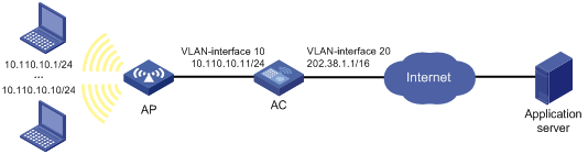
Network requirements
As shown in Figure 10, a company uses private IP address on network 192.168.0.0/16 and public IP addresses 202.38.1.2 and 202.38.1.3. Configure dynamic NAT444 to meet the following requirements:
· Only users on subnet 192.168.1.0/24 can use public IP addresses 202.38.1.2 and 202.38.1.3 to access the Internet.
· The port range for the public IP addresses is 1024 to 65535.
· The port block size is 300.
· If the ports in the assigned port block are all used, extend another port block for users.
Configuration procedures
1. Click the system view tab at the bottom of the page.
2. From the navigation tree, select Network Configuration > Network Services >NAT.
3. Click Dynamic NAT444.
4. Click the add icon.
The New Outbound Dynamic NAT444 Rule page opens.
5. Click the add icon next to the address group list.
The New NAT444 Address Group window opens.
6. Set the group ID to 0, port range to 1024 to 65535, port block size to 300, and extended port blocks to 1.
7. Add IP address range 202.38.1.2 to 202.38.1.3.
8. Click Apply.
9. On the NAT configuration page, click the add icon.
The New Outbound Dynamic NAT444 Rule page opens.
10. Add IPv4 ACL 2000 to permit packets only from subnet 192.168.1.0/24 to pass through.
11. Select VLAN-interface 20 from the interface list.
12. Select group 0 from the address group list.
13. Click Apply.
Verifying the configuration
# Verify that Client A on the internal network can access the external server, but Client B and Client C cannot. (Details not shown.)
IPv4 static route configuration example
Network requirements
As shown in Figure 11, configure IPv4 static routes on the ACs for the clients to communicate with each other.

Configuration procedure
1. On AC A, configure a default route:
a. Click the system view tab at the bottom of the page.
b. From the navigation tree, select Network Configuration > Network Routing.
c. Click the Static Routing tab.
d. Click IPv4 static routing.
e. Configure the default route:
- Set the destination IP address to 0.0.0.0.
- Set the mask length to 0.
- Set the next hop address to 1.1.4.2.
2. On AC B, configure static routes to reach Client A and Client C:
a. Click the system view tab at the bottom of the page.
b. From the navigation tree, select Network Configuration > Network Routing.
c. Click the Static Routing tab.
d. Click IPv4 static routing.
e. Configure a static route to the network that contains Client A:
- Set the destination address to 1.1.3.0.
- Set the mask length to 24.
- Set the next hop address to 1.1.5.6.
f. Configure a static route to the network that contains Client C:
- Set the destination address to 1.1.2.0.
- Set the mask length to 24.
- Set the next hop address to 1.1.4.1.
3. On AC C, configure a default route:
a. Click the system view tab at the bottom of the page.
b. From the navigation tree, select Network Configuration > Network Routing.
c. Click the Static Routing tab.
d. Click IPv4 static routing.
e. Configure the default route:
- Set the destination address to 0.0.0.0.
- Set the mask length to 0.
- Set the next hop address to 1.1.5.5.
Verifying the configuration
# Verify that the clients can ping each other. (Details not shown.)
IPv6 static route configuration example
Network requirements
As shown in Figure 12, configure IPv6 static routes on the ACs for the clients to communicate with each other.

Configuration procedure
1. On AC A, configure an IPv6 default route:
a. Click the system view tab at the bottom of the page.
b. From the navigation tree, select Network Configuration > Network Routing.
c. Click the Static Routing tab.
d. Click IPv6 static routing.
e. Configure the IPv6 default route:
- Set the destination IP address to ::.
- Set the mask length to 0.
- Set the next hop address to 4::2.
2. On AC B, configure IPv6 static routes to reach Client A and Client C:
a. Click the system view tab at the bottom of the page.
b. From the navigation tree, select Network Configuration > Network Routing.
c. Click the Static Routing tab.
d. Click IPv6 static routing.
e. Configure an IPv6 static route to the network that contains Client A:
- Set the destination address to 3::2.
- Set the mask length to 64.
- Set the next hop address to 5::1.
f. Configure an IPv6 static route to the network that contains Client C:
- Set the destination address to 1::2.
- Set the mask length to 64.
- Set the next hop address to 4::1.
3. On AC C, configure an IPv6 default route:
a. Click the system view tab at the bottom of the page.
b. From the navigation tree, select Network Configuration > Network Routing.
c. Click the Static Routing tab.
d. Click IPv6 static routing.
e. Configure the IPv6 default route:
- Set the destination address to ::.
- Set the mask length to 0.
- Set the next hop address to 5::2.
Verifying the configuration
# Verify that the clients can ping each other. (Details not shown.)
Static IPv6 address configuration example
Network requirements
As shown in Figure 13, the client generates an IPv6 address through stateless address autoconfiguration.
Assign a global unicast IPv6 address to VLAN-interface 1 of the AC.
Configuration procedure
1. Configure basic functions on the AC. For more information about the configuration, see WLAN Configuration Guide. (Details not shown.)
2. Configure an IPv6 address for VLAN-interface 1:
a. Click the system view tab at the bottom of the page.
b. From the navigation tree, select Network Configuration > Network Services > IP Services.
c. Click the IPv6 tab.
d. Access the details page for VLAN-interface 1 to perform the following tasks:
- Configure the IPv6 address of the interface as 2001::1.
- Set the prefix length to 64.
3. Configure VLAN-interface 1 to advertise RA messages.
a. Click the system view tab at the bottom of the page.
b. From the navigation tree, select Network Configuration > Network Services > ND. You are placed on the ND tab.
c. Access the advanced settings page to configure the RA settings.
d. Configure VLAN-interface 1 to advertise RA messages.
4. Install IPv6 on the client. The client automatically generates an IPv6 address based on the address prefix information contained in the RA message.
Verifying the configuration
# Verify that the client and the AC can ping each other.
DHCP server configuration example
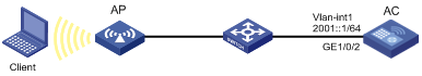
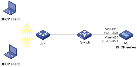
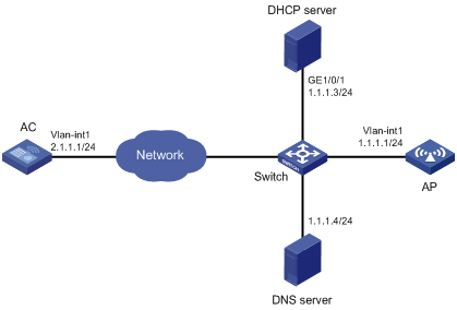
Network requirements
As shown in Figure 14, the DHCP server (AC) assigns IP addresses to the AP and DHCP clients on subnet 10.1.1.0/24, which is subnetted into 10.1.1.0/25 and 10.1.1.128/25. The AC is connected to the clients and the AP through two VLAN interfaces: VLAN-interface 10 at 10.1.1.1/25 and VLAN-interface 20 at 10.1.1.129/25.
Configure DHCP server on the AC to assign an IP address on subnet 10.1.1.0/25 to the AP and IP addresses on subnet 10.1.1.128/25 to DHCP clients.
Configuration procedure
1. Click the system view tab at the bottom of the page.
2. Configure VLANs and VLAN interfaces:
a. From the navigation tree, select Network Configuration > VLAN. You are placed on the VLAN tab.
b. Create VLANs and assign IP addresses to VLAN interfaces:
- Create VLAN 10 and assign IP address 10.1.1.1/25 to VLAN-interface 10.
- Create VLAN 20 and assign IP address 10.1.1.129/25 to VLAN-interface 20.
3. Configure the DHCP server:
a. From the navigation tree, select Network Configuration > Network Services > DHCP/DNS. You are placed on the DHCP tab.
b. Enable DHCP.
c. Specify VLAN-interface 10 and VLAN-interface 20 as DHCP servers.
d. Click the address pool link and perform the following tasks:
- Create the address pool pool1, specify 10.1.1.0/25 as the subnet for dynamic assignment, and specify 10.1.1.1 as the gateway.
- Create the address pool pool2, specify 10.1.1.128/25 as the subnet for dynamic assignment, and specify 10.1.1.129 as the gateway.
e. Access the advanced settings page to perform the following tasks:
- Set the maximum number of ping packets to 1.
- Set the ping response timeout time to 500 milliseconds.
4. Click the network view tab at the bottom of the page.
5. Configure a wireless service:
a. From the navigation tree, select Wireless Configuration > Wireless Networks.
b. Add a wireless service:
- Create a wireless service named service.
- Set the SSID to office.
- Specify the default VLAN 20.
- Enable the wireless service.
6. Configure the AP:
a. From the navigation tree, select Wireless Configuration > AP Management. You are placed on the AP tab.
b. Add and configure the AP:
- Set the AP name to AP1, and set the AP model and serial ID.
- Click the edit icon in the operation column for AP 1.
- Click the SSID setting tab, and bind the wireless service service to the 5 GHz radio of AP 1.
7. Configure the AP radio:
a. From the navigation tree, select Wireless Configuration > AP Management. You are placed on the AP tab.
b. Set the status of the 5 GHz radio of AP 1 to On.
Verifying the configuration
1. Verify that the AP can obtain an IP address on subnet 10.1.1.0/25 and the gateway address from the DHCP server.
2. Verify that the DHCP clients can obtain IP addresses on subnet 10.1.1.128/25 and the gateway address from the DHCP server.
DHCP relay agent configuration example
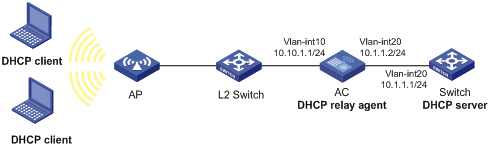
Network requirements
As shown in Figure 15, the DHCP clients and the DHCP server are in different subnets. The DHCP clients reside in subnet 10.10.1.0/24 and the DHCP server is at 10.1.1.1/24. An AC is deployed between the DHCP clients and the DHCP server. The AC is connected to the network in which the DHCP clients reside through VLAN-interface 10 at 10.10.1.1/24. The AC is connected to the DHCP server through VLAN-interface 20 at 10.1.1.2/24.
Configure the DHCP relay agent on the AC, so the DHCP clients can obtain IP addresses and other configuration parameters from the DHCP server.
Configuration procedure
1. Assign IP addresses to interfaces. (Details not shown.)
2. Configure the DHCP server. (Details not shown.)
3. Configure basic settings on the AC. (Details not shown.)
4. Configure the DHCP relay agent:
a. Click the system view tab at the bottom of the page.
b. From the navigation tree, select Network Configuration > Network Services > DHCP/DNS. You are placed on the DHCP tab.
c. Perform the following tasks:
- Enable DHCP.
- Specify VLAN-interface 10 as the DHCP relay agent.
- Specify the DHCP server address 10.1.1.1.
Verifying the configuration
Verify that the DHCP clients can obtain IP addresses and other configuration parameters from the DHCP server through the DHCP relay agent.
DHCP snooping configuration example
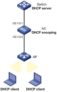
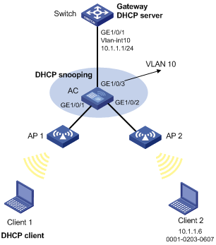
Network requirements
As shown in Figure 16, the AC is connected to a DHCP server through GigabitEthernet 1/0/1 and to an AP through GigabitEthernet 1/0/2. Configure DHCP snooping on the AC to meet the following requirements:
· Allow only the interface connected to the authorized DHCP server to forward packets from the DHCP server.
· Record the clients' IP-to-MAC binding information in DHCP-REQUEST packets and in DHCP-ACK packets received by trusted ports.
Configuration procedure
1. Configure the DHCP server. (Details not shown.)
2. Configure basic settings on the AC. (Details not shown.)
3. Configure the DHCP snooping device:
a. Click the system view tab at the bottom of the page.
b. From the navigation tree, select Network Configuration > Network Services > DHCP/DNS.
c. Click the DHCP Snooping tab.
d. Perform the following tasks:
- Enable DHCP snooping.
- Configure GigabitEthernet 1/0/1, the interface connected to the authorized DHCP server, as the trusted port.
- Configure GigabitEthernet 1/0/2, the interface connected to the DHCP clients, to record DHCP snooping entries.
Verifying the configuration
# Verify that the AC maintains DHCP snooping entries for clients that have obtained IP addresses through DHCP.
IPv4 static DNS configuration example
Network requirements
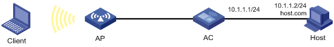
As shown in Figure 17, configure a static DNS entry on the AC, so the AC can use the domain name host.com to access the host at 10.1.1.2.
Configuration procedure
1. Click the system view tab at the bottom of the page.
2. From the navigation tree, select Network Configuration > Network Services > DHCP/DNS.
3. Click the IPv4 DNS tab.
4. Create a static DNS entry:
¡ Configure the host name as host.com.
¡ Configure the IPv4 address as 10.1.1.2.
Verifying the configuration
Use the ping host.com command on the AC to verify the following items:
· The ping operation succeeds.
· The AC can use static domain name resolution to resolve the domain name host.com into the IPv4 address 10.1.1.2.
IPv4 dynamic DNS configuration example
Network requirements
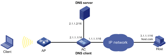
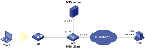
As shown in Figure 18, the DNS server at 2.1.1.2/16 has a com domain that stores the mapping between the domain name host and the IPv4 address 3.1.1.1/16.
Configure dynamic DNS and the DNS suffix com on the AC that acts as a DNS client. The AC can use the domain name host to access the host whose domain name is host.com and IPv4 address is 3.1.1.1/16.
Configuration procedure
1. Map the domain name host.com to the IPv4 address 3.1.1.1 on the DNS server. (Details not shown.)
2. Configure static routes or dynamic routing protocols on the devices to make sure the devices can reach each other. (Details not shown.)
3. Configure DNS client on the AC:
a. Click the system view tab at the bottom of the page.
b. From the navigation tree, select Network Configuration > Network Services > DHCP/DNS.
c. Click the IPv4 DNS tab.
d. Specify the DNS server address 2.1.1.2.
e. Access the advanced settings page and add the domain name suffix com.
Verifying the configuration
Use the ping host command on the AC to verify the following items:
· The ping operation succeeds.
· The AC can resolve the domain name host.com into the IPv4 address 3.1.1.1 through the DNS server.
IPv4 DNS proxy configuration example
Network requirements
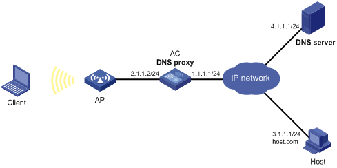
As shown in Figure 19, the LAN has a large number of devices deployed. The devices access the DNS server for domain name resolution. If the DNS server's IP address changes, the administrator must modify the DNS server address on each device, which takes a lot of time.
To simplify the configuration, configure the AC as the DNS proxy. Specify the real DNS server address on the AC. Specify the DNS proxy address as the DNS server address on the other devices. If the DNS server address changes, the administrator only needs to modify the DNS server address on the DNS proxy.
Configuration procedure
1. Configure static routes or dynamic routing protocols on the devices to make sure the devices can reach each other. (Details not shown.)
2. Configure the DNS server. (Details not shown.)
3. Configure DNS proxy on the AC:
a. Click the system view tab at the bottom of the page.
b. From the navigation tree, select Network Configuration > Network Services > DHCP/DNS.
c. Click the IPv4 DNS tab.
d. Specify the DNS server address 4.1.1.1.
e. On the advanced settings page, enable DNS proxy.
4. Configure DNS clients.
Specify the DNS proxy address 2.1.1.2 as the DNS server address on the other devices that act as DNS clients.
Verifying the configuration
Use the ping host.com command on a DNS client to verify the following items:
· The ping operation succeeds.
· The client can resolve the domain name host.com into the IPv4 address 3.1.1.1 through the DNS server.
IPv6 static DNS configuration example
Network requirements
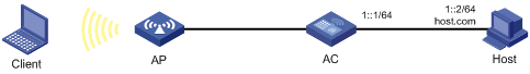
As shown in Figure 20, configure a static DNS entry on the AC, so the AC can use the domain name host.com to access the host at 1::2.
Configuration procedure
1. Click the system view tab at the bottom of the page.
2. From the navigation tree, select Network Configuration > Network Services > DHCP/DNS.
3. Click the IPv6 DNS tab.
4. Create a static DNS entry:
¡ Configure the host name as host.com.
¡ Configure the IPv6 address as 1::2.
Verifying the configuration
Use the ping ipv6 host.com command on the AC to verify the following items:
· The ping operation succeeds.
· The AC can use static domain name resolution to resolve the domain name host.com into the IPv6 address 1::2.
IPv6 dynamic DNS configuration example
Network requirements
As shown in Figure 21, the DNS server at 2::2/64 has a com domain that stores the mapping between the domain name host and the IPv6 address 1::1/64.
Configure dynamic DNS and the DNS suffix com on the AC that acts as a DNS client. The AC can use the domain name host to access the host whose domain name is host.com and IPv6 address is 1::1/64.
Configuration procedure
1. Map the domain name host.com to the IPv6 address 1::1 on the DNS server. (Details not shown.)
2. Configure static routes or dynamic routing protocols on the devices to make sure the devices can reach each other. (Details not shown.)
3. Configure DNS client on the AC:
a. Click the system view tab at the bottom of the page.
b. From the navigation tree, select Network Configuration > Network Services > DHCP/DNS.
c. Click the IPv6 DNS tab.
d. Specify the DNS server address 2::2.
e. Access the advanced settings page and add the domain name suffix com.
Verifying the configuration
Use the ping ipv6 host command on the AC to verify the following items:
· The ping operation succeeds.
· The AC can resolve the domain name host.com into the IPv6 address 1::1 through the DNS server.
IPv6 DNS proxy configuration example
Network requirements
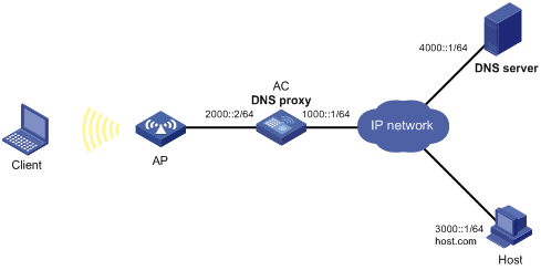
As shown in Figure 22, the LAN has a large number of devices deployed. The devices access the DNS server for domain name resolution. If the DNS server's IPv6 address changes, the administrator must modify the DNS server address on each device, which takes a lot of time.
To simplify the configuration, configure the AC as the DNS proxy. Specify the real DNS server address on the AC. Specify the DNS proxy address as the DNS server address on the other devices. If the DNS server address changes, the administrator only needs to modify the DNS server address on the DNS proxy.
Configuration procedure
1. Configure static routes or dynamic routing protocols on the devices to make sure the devices can reach each other. (Details not shown.)
2. Configure the DNS server. (Details not shown.)
3. Configure DNS proxy on the AC:
a. Click the system view tab at the bottom of the page.
b. From the navigation tree, select Network Configuration > Network Services > DHCP/DNS.
c. Click the IPv6 DNS tab.
d. Specify the DNS server address 4000::1.
e. On the advanced settings page, enable DNS proxy.
4. Configure DNS clients.
Specify the DNS proxy address 2000::2 as the DNS server address on the other devices that act as DNS clients.
Verifying the configuration
Use the ping ipv6 host.com command on a DNS client to verify the following items:
· The ping operation succeeds.
· The client can resolve the domain name host.com into the IPv6 address 3000::1 through the DNS server.
IGMP snooping configuration example
|
Hardware series |
Model |
Configuration example compatibility |
|
WX1800H series |
WX1804H WX1810H WX1820H |
Yes |
|
WX2500H series |
WX2510H WX2510H-F WX2540H WX2540H-F WX2560H |
Yes |
|
WX3000H series |
WX3010H WX3010H-X WX3010H-L WX3024H WX3024H-L WX3024H-F |
Yes: · WX3010H · WX3010H-X · WX3024H · WX3024H-F No: · WX3010H-L · WX3024H-L |
|
WX3500H series |
WX3510H WX3520H WX3520H-F WX3540H |
Yes |
|
WX5000 series |
WX5510E |
Yes |
|
WX5500 series |
WX5540E WX5540H WX5560H WX5580H |
Yes |
|
Access controller module |
LSUM1WCME0 EWPXM1WCME0 LSQM1WCMX20 LSUM1WCMX20RT LSQM1WCMX40 LSUM1WCMX40RT EWPXM2WCMD0F EWPXM1MAC0F |
Yes |
Network requirements
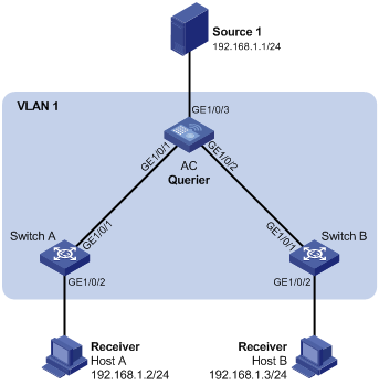
As shown in Figure 23:
· The network is a Layer 2-only network.
· Source 1 sends multicast data to the multicast group 224.1.1.1, and Host A and Host B are receivers of the group.
· Host A and Host B run IGMPv2. The AC, Switch A, and Switch B run IGMPv2 snooping, and the AC acts as the IGMP querier.
Configure the devices to meet the following requirements:
· For IGMP snooping forwarding entries to be created, configure the source IP address of IGMP queries as a non-zero IP address on the AC.
· To prevent unknown multicast data from being flooded in VLAN 1, enable the devices to drop unknown multicast data.
Configuration procedure
1. Configure the AC:
a. Click the system view tab at the bottom of the page.
b. From the navigation tree, select Network Configuration > Network Services > Multicast. You are placed on the IGMP Snooping tab.
c. Enable IGMP snooping.
d. Access the page for enabling IGMP snooping on a VLAN to perform the following tasks:
- Set the VLAN ID to 1.
- Set the IGMP snooping version to 2.
- Enable dropping unknown multicast data.
- Enable the AC to act as the IGMP querier.
- Set the source IP address to 192.168.1.10 for IGMP general queries.
- Set the source IP address to 192.168.1.10 for IGMP group-specific queries.
2. Configure Switch A:
# Enable IGMP snooping for VLAN 1, set the IGMP snooping version to 2, and then enable dropping unknown multicast data. (Details not shown.)
3. Configure Switch B in the same way Switch A is configured. (Details not shown.)
Verifying the configuration
1. Send IGMP reports from Host A and Host B to join the multicast group 224.1.1.1. (Details not shown.)
2. Send multicast data from the source to the multicast group. (Details not shown.)
3. Access the Network Configuration> Network Services > Multicast > IGMP snooping > Entries page to verify that GigabitEthernet 1/0/1 and GigabitEthernet 1/0/2 are host ports of VLAN 1.
MLD snooping configuration example
|
Hardware series |
Model |
Configuration example compatibility |
|
WX1800H series |
WX1804H WX1810H WX1820H |
Yes |
|
WX2500H series |
WX2510H WX2510H-F WX2540H WX2540H-F WX2560H |
Yes |
|
WX3000H series |
WX3010H WX3010H-X WX3010H-L WX3024H WX3024H-L WX3024H-F |
Yes: · WX3010H · WX3010H-X · WX3024H · WX3024H-F No: · WX3010H-L · WX3024H-L |
|
WX3500H series |
WX3510H WX3520H WX3520H-F WX3540H |
Yes |
|
WX5000 series |
WX5510E |
Yes |
|
WX5500 series |
WX5540E WX5540H WX5560H WX5580H |
Yes |
|
Access controller modules |
LSUM1WCME0 EWPXM1WCME0 LSQM1WCMX20 LSUM1WCMX20RT LSQM1WCMX40 LSUM1WCMX40RT EWPXM2WCMD0F EWPXM1MAC0F |
Yes |
Network requirements
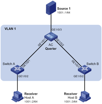
As shown in Figure 24:
· The network is a Layer 2-only network.
· Source 1 sends IPv6 multicast data to the IPv6 multicast group FF1E::101. Host A and Host B are receivers of the group.
· Host A and Host B run MLDv1. The AC, Switch A, and Switch B run MLDv1 snooping, and the AC acts as the MLD querier.
To prevent unknown IPv6 multicast data from being flooded in VLAN 1, enable all the devices to drop unknown IPv6 multicast data.
Configuration procedure
1. Configure the AC:
a. Click the system view tab at the bottom of the page.
b. From the navigation tree, select Network Configuration > Network Services > Multicast. You are placed on the IGMP Snooping tab.
c. Click the MLD Snooping tab, and then enable MLD snooping.
d. Access the page for enabling MLD snooping on a VLAN to perform the following tasks:
- Set the VLAN ID to 1.
- Set the MLD snooping version to 1.
- Enable dropping unknown IPv6 multicast data.
- Enable the AC to act as an MLD querier.
- Apply the configuration.
2. Configure Switch A:
# Enable MLD snooping for VLAN 1, set the MLD snooping version to 1, and then enable dropping unknown IPv6 multicast data. (Details not shown.)
3. Configure Switch B in the same way Switch A is configured. (Details not shown.)
Verifying the configuration
1. Send MLD reports from Host A and Host B to join the IPv6 multicast group FF1E::101. (Details not shown.)
2. Send IPv6 multicast data from Source 1 to the IPv6 multicast group. (Details not shown.)
3. Access the Network Configuration> Network Services > Multicast > MLD snooping > Entries page to verify that GigabitEthernet 1/0/1 and GigabitEthernet 1/0/2 are host ports of VLAN 1.
Proxy ARP configuration example
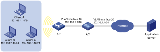
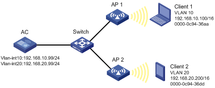
Network requirements
As shown in Figure 25, Client 1 and Client 2 have the same IP prefix and mask, but they are located on different subnets separated by the AC. Client 1 belongs to VLAN 10, and Client 2 belongs to VLAN 20. No default gateway is configured on Client 1 and Client 2.
Configure proxy ARP on the AC to enable communication between the two clients.
Configuration procedure
1. Configure VLAN 10 and VLAN 20, and assign IP addresses to VLAN-interface 10 and VLAN-interface 20:
a. Click the system view tab at the bottom of the page.
b. From the navigation tree, select Network Configuration > VLAN. You are placed on the VLAN tab.
c. Create VLAN 10, and assign IP address 192.168.10.99/24 to VLAN-interface 10.
d. Create VLAN 20, and assign IP address 192.168.20.99/24 to VLAN-interface 20.
2. Enable proxy ARP on VLAN-interface 10 and VLAN-interface 20.
a. Click the system view tab at the bottom of the page.
b. From the navigation tree, select Network Configuration > Network Services > ARP. You are placed on the ARP tab.
c. Access the advanced settings page to configure proxy ARP.
- Enable proxy ARP on VLAN-interface 10.
- Enable proxy ARP on VLAN-interface 20.
Verifying the configuration
# Verify that Client 1 and Client 2 can ping each other.
ARP attack protection configuration example
Network requirements
As shown in Figure 26, Client 1 obtains an IP address from the switch (DHCP server). Client 2 is manually assigned IP address 10.1.1.6.
Configure the AC to perform ARP packet validity check and user validity check for connected clients.
Configuration procedure
1. Assign all interfaces to VLAN 10, and specify the IP address of VLAN-interface 10 on the switch. (Details not shown.)
2. Configure the DHCP server on the switch. (Details not shown.)
3. Configure Client 1 (the DHCP client) and Client 2. (Details not shown.)
4. Enable DHCP snooping on the AC:
a. Click the system view tab at the bottom of the page.
b. From the navigation tree, select Network Configuration > Network Services > DHCP/DNS.
c. Click the DHCP Snooping tab.
d. Enable DHCP snooping.
e. Configure GigabitEthernet 1/0/3 as a trusted port.
f. Enable recording of client information in DHCP snooping entries on GigabitEthernet 1/0/1.
5. Configure ARP detection on the AC:
a. Click the system view tab at the bottom of the page.
b. From the navigation tree, select Network Configuration > Network Services > ARP. You are placed on the ARP tab.
c. Access the advanced settings page to configure ARP detection under ARP attack protection.
d. Enable ARP detection for VLAN 10.
e. Access the advanced settings page for ARP detection to perform the following tasks:
- Configure GigabitEthernet 1/0/3 as a trusted interface.
By default, an interface is an untrusted interface.
- Enable ARP packet validity check by checking the sender MAC address, target MAC address, and IP addresses of ARP packets.
After the configurations are completed, the AC first checks the validity of ARP packets received on GigabitEthernet 1/0/1 and GigabitEthernet 1/0/2. If the ARP packets are confirmed valid, the switch performs user validity check by using the DHCP snooping entries.
Verifying the configuration
# Access the ARP page to verify that ARP entry for Client 1 is created and no ARP entry is created for Client 2.
Using the device as the Stelnet server for password authentication configuration example
Network requirements
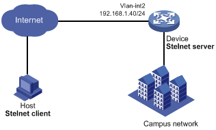
As shown in Figure 27:
· The device acts as the Stelnet server and uses password authentication.
· The username and password of the client are saved on the device.
Establish an Stelnet connection between the host and the device, so you can log in to the device to configure and manage the device.
Configuration procedure
1. Configure the Stelnet server:
a. Click the system view tab at the bottom of the page.
b. From the navigation tree, select Network Configuration > Management Protocols.
c. Click the SSH tab.
d. Enable the Stelnet service.
2. Configure the VLAN interface:
a. Click the system view tab at the bottom of the page.
b. From the navigation tree, select Network Configuration > VLAN.
c. On the VLAN tab, create VLAN 2.
d. Click the edit icon for VLAN 2.
The Edit VLAN page opens.
e. Add GigabitEthernet 1/0/2 to the untagged port list.
f. Select Configure VLAN interface.
g. Set the IPv4 address/mask to 192.168.1.40/24.
3. Configure the administrator account:
a. Click the system view tab at the bottom of the page.
b. From the navigation tree, select System > Administrators.
c. Click the add icon.
d. Set the username and password to client and aabbcc, respectively.
e. Select network-admin from the user roles list.
f. Select SSH for the permitted access types parameter.
Verifying the configuration
This example uses PuTTY0.58 to verify the configuration.
1. Execute PuTTY.
2. Enter 192.168.1.40 in the Host Name (or IP address) field.
3. Click Open.
4. Verify that you can use username client and password aabbcc to log in to the configuration page of the device.
NTP configuration example
Network requirements
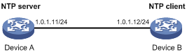
As shown in Figure 28:
· Configure the local clock of Device A as a reference source, with the stratum level 2.
· Set Device B to client mode and use Device A as the NTP server for Device B.
Configuration procedure
1. Configure Device A (NTP server):
a. Click the system view tab at the bottom of the page.
b. From the navigation tree, select Network Configuration > Management Protocols.
c. Click the NTP tab.
d. Enable the NTP service.
e. Specify the IP address of the local clock as 127.127.1.0.
f. Configure the stratum level of the local clock as 2.
2. Configure Device B:
a. Click the system view tab at the bottom of the page.
b. From the navigation tree, select System > Management. You are placed on the Settings tab.
c. Select automatic time synchronization with a trusted time source, and then select NTP as the time protocol.
d. Specify the IP address of Device A as 1.0.1.11, and configure Device B to operate in server mode.
Verifying the configuration
# Verify that Device B has synchronized to Device A, and the clock stratum level is 3 on Device B and 2 on Device A.
LLDP configuration example
Network requirements
As shown in Figure 29, configure LLDP on the AC and switch to meet the following requirements:
· The AC can discover the switch and obtain system and configuration information from the switch.
· The switch cannot discover the AC.

Configuration procedure
1. Configure LLDP on the AC:
a. Click the system view tab at the bottom of the page.
b. From the navigation tree, select Network Configuration > Management Protocols.
c. Click the LLDP tab.
d. Enable LLDP globally.
e. Access the interface status page, and then enable LLDP on GigabitEthernet 1/0/1.
f. Access the interface configuration page to perform the following tasks:
- Enable the nearest bridge agent function on GigabitEthernet 1/0/1.
- Set the operating mode of the interface to Rx mode to configure the interface to only receive LLDP frames.
Then, the AC can discover neighbors.
2. Configure LLDP on the switch:
a. Click the system view tab at the bottom of the page.
b. From the navigation tree, select Network Configuration > Management Protocols > LLDP.
c. Enable LLDP globally on the switch.
d. Access the interface status page, and then enable LLDP on GigabitEthernet 1/0/2.
e. Access interface configuration page to perform the following tasks:
- Enable the nearest bridge agent function on GigabitEthernet 1/0/2.
- Set the operating mode of the interface to Tx mode to configure the interface to only transmit LLDP frames.
Then, the switch cannot discover neighbors.
Verifying the configuration
1. Verify that you can view information about the switch on the LLDP neighbor information page of the AC.
2. Verify that the LLDP neighbor information page of the switch does not contain an entry for the AC.
Network security configuration examples
ACL-based packet filter configuration example
Network requirements
As shown in Figure 30, a company interconnects its departments through the AC. Configure the packet filter on the AC to meet the following requirements:
· Permit access from the President's office at any time to the financial database server.
· Permit access from the Financial Department to the financial database server only during working hours (from 8:00 to 18:00) on working days.
· Deny access from any other department to the financial database server.
Configuration procedure
1. Click the system view tab at the bottom of the page.
2. From the navigation tree, select Network Security > Packet Filter.
3. Create a packet filter policy:
a. Select VLAN-interface 10.
b. Select the outbound application direction.
c. Select the IPv4 ACL type for packet filter.
4. Create an advanced IPv4 ACL and configure the following rules in the order they are described:
|
Action |
Protocol type |
IP/wildcard mask |
Time range |
|
Permit |
256 |
Source: 192.168.1.0/0.0.0.255 Destination: 192.168.0.100/0 |
N/A |
|
Permit |
256 |
Source: 192.168.2.0/0.0.0.255 Destination: 192.168.0.100/0 |
Create a time range named work: · Specify the start time as 08:00. · Specify the end time as 18:00. · Select Monday through Friday. |
|
Deny |
256 |
Destination: 192.168.0.100/0 |
N/A |
5. Enable rule match counting for the ACL.
Verifying the configuration
1. Ping the database server from different departments to verify the following items:
¡ You can access the server from the President's office at any time.
¡ You can access the server from the Financial Department during the working hours on working days.
¡ You cannot access the server from the Marketing Department at any time.
2. Access the ACL rule Web interface, verify that the ACL rules are active and the number of matching packets is displayed.
QoS configuration example
Network requirements
As shown in Figure 31, configure QoS for the device, so the device forwards packets from different departments in the following order when congestion occurs:
· Administration department.
· R&D department.
· Marketing department.
Configuration procedure
1. Configure QoS policies:
a. Click the system view tab at the bottom of the page.
b. From the navigation tree, select Network Security > Traffic Policy.
c. Click the QoS Policies tab.
d. Apply a QoS policy to the incoming traffic of GigabitEthernet 1/0/2.
e. Modify the applied QoS policy as follows:
- Create IPv4 ACL 2000, and add a rule to permit packets with source IP address 192.168.1.0 and mask 0.0.0.255.
- Configure the ACL as a match criterion of a class, and specify the associated behavior to mark the matched packets with 802.1p priority 2.
f. Apply a QoS policy to the incoming traffic of GigabitEthernet 1/0/3.
g. Modify the applied QoS policy as follows:
- Create IPv4 ACL 2002, and add a rule to permit packets with source IP address 192.168.2.0 and mask 0.0.0.255.
- Configure the ACL as a match criterion of a class, and specify the associated behavior to mark the matched packets with 802.1p priority 0.
h. Apply a QoS policy to the incoming traffic of GigabitEthernet 1/0/4.
i. Modify the applied QoS policy as follows:
- Create IPv4 ACL 2003, and add a rule to permit packets with source IP address 192.168.1.0 and mask 0.0.0.255.
- Configure the ACL as a match criterion of a class, and specify the associated behavior to mark the matched packets with 802.1p priority 1.
2. Configure priority mapping:
a. Click the system view tab at the bottom of the page.
b. From the navigation tree, select Network Security > Traffic Policy.
c. Click the Priority Mapping tab.
d. Click Port Priority.
e. Configure GigabitEthernet 1/0/1, GigabitEthernet 1/0/2, GigabitEthernet 1/0/3, and GigabitEthernet 1/0/4 to trust the 802.1p priority.
f. Click Apply.
g. On the Priority Mapping tab, click Priority Map-table.
h. Configure the 802.1p-to-local priority mapping table to map 802.1p priority values 0, 1, and 2 to local precedence values 0, 1, and 2, respectively.
Verifying the configuration
On the QoS policy page, verify that the QoS policies are applied correctly. (Details not shown.)
System configuration examples
Administrators configuration example
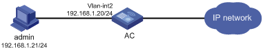
Network requirements
As shown in Figure 32, configure an administrator account with the username webuser and password 12345 on the AC to meet the following requirements:
· Allow the user to use the account to log in to the AC through HTTP.
· Perform local authentication for the user that uses the administrator account to log in to the AC.
· Assign the network-admin user role to the authenticated user.
Configuration procedure
1. Click the system view tab at the bottom of the page.
2. Configure the VLAN and VLAN interface:
a. From the navigation tree, select Network Configuration > VLAN. You are placed on the VLAN tab.
b. Create VLAN 2.
c. Access the edit page for VLAN 2 to perform the following tasks:
- Add the interface that connects to the admin's PC to the tagged port list.
- Create VLAN-interface 2.
- Assign the IP address 192.168.1.20/24 to VLAN-interface 2.
3. Configure an administrator account:
a. From the navigation tree, select System > Administrators. You are placed on the Administrators tab.
b. Create and configure an administrator account:
- Set the username and the password to webuser and 12345, respectively.
- Select the network-admin user role.
- Specify HTTP and HTTPS as the permitted access types.
Verifying the configuration
1. Access the System > Administrators page to verify that the administrator account is successfully added.
2. Enter http://192.168.1.20 in the address bar to verify the following items:
¡ You can use the administrator account to log in to the Web interface.
¡ After login, you can configure the device.
Network configuration examples
Wireless configuration examples
CAPWAP tunnel establishment through DHCP configuration example
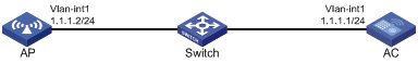
Network requirements
As shown in Figure 33, configure the AP to obtain its IP address and the AC's IP address from the DHCP server (the AC) through DHCP Option 43. The AP uses the IP address of the AC to establish a CAPWAP tunnel with the AC.
Configuration procedure
1. Click the system view tab at the bottom of the page.
2. Set the AC IP address:
a. From the navigation tree, select Network Configuration > VLAN. You are placed on the VLAN tab.
b. Click the edit icon in the operation column for VLAN-interface 1.
c. Set the IP address to 1.1.1.1/24.
3. Configure DHCP:
a. From the navigation tree, select Network Configuration > Network Services > DHCP/DNS. You are placed on the DHCP tab.
b. Enable the DHCP service.
c. Access the DHCP configuration page to select DHCP server from the DHCP service list for VLAN-interface 1.
d. Access the address pool configuration page. You are placed on the Assigned Address tab.
e. Perform the following tasks:
- Create an address pool named pool1.
- Specify subnet 1.1.1.0/24 for dynamic IP address assignment.
f. Click the DHCP Options tab.
g. Perform the following tasks:
- Set the gateway address to 1.1.1.1.
- Configure the content of Option 43 as 800700000101010101.
4. Click the network view tab at the bottom of the page.
5. Configure the AP:
a. From the navigation tree, select Wireless Configuration > AP Management. You are placed on the AP tab.
b. Add and configure AP 1:
- Set the AP name to AP1.
- Set the AP model and serial ID.
Verifying the configuration
# Access the Wireless Configuration > AP Management > AP page to verify that AP 1 has come online.
# Access the AP details page to verify the following information:
· The AP has obtained an IP address.
· The AC IP address is 1.1.1.1/24.
· The AC discovery type is DHCP.
CAPWAP tunnel establishment through DNS configuration example
Network requirements
As shown in Figure 34, configure the AP to obtain the IP address of the AC through DNS to establish a CAPWAP tunnel with the AC.
Configuration procedure
1. On the DHCP server, specify subnet 1.1.1.0/24 for IP address assignment, and set the domain name suffix of the AC to abc. (Details not shown.)
2. On the DNS server, configure a mapping between domain name host.abc and IP address 1.1.1.1/24. (Details not shown.)
3. Click the system view tab at the bottom of the page.
4. Set the AC's IP address:
a. From the navigation tree, select Network Configuration > VLAN. You are placed on the VLAN tab.
b. Click the edit icon in the operation column for VLAN-interface 1.
c. Set the IP address to 1.1.1.1/24.
5. Click the network view tab at the bottom of the page.
6. Configure the AP:
a. From the navigation tree, select Wireless Configuration > AP Management. You are placed on the AP tab.
b. Add and configure AP 1:
- Set the AP name to AP1.
- Set the AP model and serial ID.
Verifying the configuration
# Access the Wireless Configuration > AP Management > AP page to verify that AP 1 has come online.
# Access the AP details page to verify the following information:
· The AP has obtained an IP address.
· The AC IP address is 1.1.1.1/24.
· The AC discovery type is DNS.
Auto AP configuration example
Network requirements
As shown in Figure 35, enable the auto AP feature on the AC. The AP obtains the AC's IP address through DHCP Option 43 and establishes a CAPWAP tunnel with the AC.
Configuration procedure
1. Click the system view tab at the bottom of the page.
2. Set the AC IP address:
a. From the navigation tree, select Network Configuration > VLAN. You are placed on the VLAN tab.
b. Click the edit icon in the operation column for VLAN-interface 1.
c. Set the IP address to 1.1.1.1/24.
3. Configure DHCP:
a. From the navigation tree, select Network Configuration > Network Services > DHCP/DNS. You are placed on the DHCP tab.
b. Enable the DHCP service.
c. Access the DHCP configuration page to select DHCP server from the DHCP service list for VLAN-interface 1.
d. Access the address pool configuration page. You are placed on the Assigned Address tab.
e. Perform the following tasks:
- Create an address pool named pool1.
- Specify subnet 1.1.1.0/24 for dynamic IP address assignment.
f. Click the DHCP Options tab.
g. Perform the following tasks:
- Set the gateway address to 1.1.1.1.
- Configure the content of Option 43 as 800700000101010101.
4. Click the network view tab at the bottom of the page.
5. Configure the AP:
a. From the navigation tree, select Wireless Configuration > AP Management.
b. Click the AP Global Settings tab.
c. Enable the auto AP feature.
Verifying the configuration
# Access the Wireless Configuration > AP Management > AP page to verify that AP 1 has come online as an auto AP.
AP group configuration example
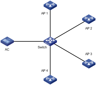
Network requirements
As shown in Figure 36, configure AP groups and add AP 1 to the AP group group1, and AP 2, AP 3, and AP 4 to the AP group group2.
Configuration procedure
1. Configure APs to obtain their IP addresses and the AC's IP address from the DHCP server. (Details not shown.)
2. Click the network view tab at the bottom of the page.
3. Configure the AP groups:
a. From the navigation tree, select Wireless Configuration > AP Management.
b. Click the AP Groups tab.
c. Add two AP groups named group1 and group2.
d. Add the AP ap1 to the AP group group1.
e. Add the APs ap2, ap3, and ap4 to the AP group group2.
Verifying the configuration
# Access the AP groups page to verify the following information:
· The AP ap1 is in the AP list of the AP group group1.
· The APs ap 2, ap 3, and ap 4 are in the AP list of the AP group group2.
Radio management configuration example
Network requirements
As shown in Figure 37, perform the following tasks to configure the 5 GHz radio of the AP:
· Set the radio type, working channel, and maximum transmit power to 802.11ac, 48, and 19 dBm, respectively.
· Set the maximum mandatory NSS, maximum supported NSS, multicast NSS, and VHT-MCS index to 2, 3, 2, and 5, respectively.
· Enable the A-MSDU and A-MPDU aggregation methods to improve network throughput.
Configuration procedure
1. Click the network view tab at the bottom of the page.
2. From the navigation tree, select Wireless Configuration > Radio Management. You are placed on the Radio Configuration tab.
3. Access the details page for all AP radio configurations.
4. Click the edit icon in the operation column for the 5 GHz radio of the AP. You are placed on the Basic tab.
5. Perform the following tasks in the basic configuration area:
a. Enable the radio.
b. Set the radio type to 802.11ac (5GHz).
c. Set the channel to 48.
d. Set the maximum transmit power to 19 dBm.
6. Perform the following tasks in the rates configuration area:
a. Set the maximum mandatory NSS to 2.
b. Set the maximum supported NSS to 3.
c. Set the multicast NSS to 2.
d. Set the VHT-MCS index to 5.
7. Perform the following tasks in the 802.11n/802.11ac configuration area:
a. Enable the A-MSDU aggregation method.
b. Enable the A-MPDU aggregation method.
8. Apply the configuration.
Verifying the configuration
# Access the Wireless Configuration > Radio Management > Radio Configuration page to verify that the configuration is correct.
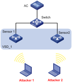
WIPS device classification and countermeasures configuration example
Network requirements
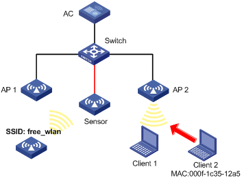
As shown in Figure 38, the sensor connects to the AC through the switch. AP 1 and AP 2 provide wireless services to clients through the SSID abc. Perform the following tasks:
· Enable WIPS for the sensor.
· Configure wireless device classification to add the MAC address 000f-1c35-12a5 to the static prohibited device list and the SSID abc to the trusted SSID list.
· Configure countermeasures to enable WIPS to take countermeasures against potential-external APs and unauthorized clients.
Configuration procedure
1. Click the network view tab at the bottom of the page.
2. Create a manual AP:
a. From the navigation tree, select Wireless Configuration > AP Management. You are placed on the AP tab.
b. Access the page for adding an AP to perform the following tasks:
- Set the AP name to Sensor.
- Specify the AP model and serial ID.
3. Configure WIPS:
a. From the navigation tree, select Wireless Configuration > Wireless Security. You are placed on the WIPS tab.
b. Access the details page for virtual security domain configuration to create the VSD VSD_1.
c. Access the details page for enabling WIPS to enable WIPS for the AP Sensor and add the AP to the VSD VSD_1.
d. Access the details page for classification policy configuration to perform the following tasks:
- Create the classification policy class1.
- Add the MAC address of Client 2 to the prohibited device list.
- Add the SSID abc to the trusted SSID list.
e. Access the details page for countermeasure policy configuration to perform the following tasks:
- Create the countermeasure policy protect.
- Configure WIPS to take countermeasures against unauthorized clients and potential-external APs.
f. Access the modifying VSD page for the VSD VSD_1 to perform the following tasks:
- Apply the classification policy class1 to the VSD VSD_1.
- Apply the countermeasure policy protect to the VSD VSD_1.
Verifying the configuration
# Verify that the AP with the MAC address 000f-e223-1616 is classified as a potential-external AP and the client with the MAC address 000f-1c35-12a5 is classified as an unauthorized client.
# Verify that WIPS has taken countermeasures against the unauthorized client with the MAC address 000f-1c35-12a5 and the potential-external AP with the MAC address 000f-e223-1616.
WIPS malformed packet and flood attack detection configuration example
Network requirements
As shown in Figure 39, configure the two APs that connect to the AC through the switch as sensors. Add Sensor 1 and Sensor 2 to the VSD VSD_1. Configure malformed packet detection and flood attack detection to enable WIPS to trigger an alarm when it detects beacon flood attacks or malformed packets with duplicated IE.
Configuration procedure
1. Click the network view tab at the bottom of the page.
2. Create a manual AP:
a. From the navigation tree, select Wireless Configuration > AP Management. You are placed on the AP tab.
b. Create two APs named Sensor 1 and Sensor 2.
c. Specify the AP model and serial ID for the APs.
3. Configure WIPS:
a. From the navigation tree, select Wireless Configuration > Wireless Security. You are placed on the WIPS tab.
b. Access the details page for virtual security domain configuration to create the VSD VSD_1.
c. Access the details page for enabling WIPS to enable WIPS for the APs Sensor 1 and Sensor 2 and add the APs to the VSD VSD_1.
d. Access the page for adding an attack detection policy to perform the following tasks:
- Create an attack detection policy.
- Enable detection on malformed packets with duplicated IE, and set the quiet time to 50 seconds.
- Enable beacon flood attack detection, and set the statistics interval, threshold, and quiet time to 100 seconds, 200, and 50 seconds, respectively.
e. Access the modifying page for the VSD VSD_1 to apply the attack detection policy to the VSD VSD_1.
Verifying the configuration
# Verify that no malformed packets or flood attack messages exist when WIPS does not detect any attacks in the WLAN.
# Verify that the number of malformed packets or flood attack messages is not zero when WIPS detects beacon flood attacks and malformed packets with duplicated IE.
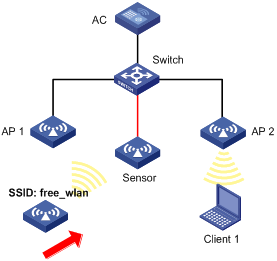
Signature-based attack detection configuration example
Network requirements
As shown in Figure 40, AP 1 and AP 2 provide wireless services for clients through the SSID abc. Enable WIPS for the sensor, and configure a signature to enable WIPS to trigger an alarm when it detects beacon frames whose SSIDs are not abc.
Configuration procedure
1. Click the network view tab at the bottom of the page.
2. Create a manual AP:
a. From the navigation tree, select Wireless Configuration > AP Management. You are placed on the AP tab.
b. Access the page for adding an AP to perform the following tasks:
- Set the AP name to Sensor.
- Specify the AP model and serial ID for the APs.
3. Configure WIPS:
a. From the navigation tree, select Wireless Configuration > Wireless Security. You are placed on the WIPS tab.
b. Access the details page for virtual security domain configuration to create the VSD vsd1.
c. Access the details page for enabling WIPS to enable WIPS for the AP Sensor and add the AP to the VSD vsd1.
d. Access the details page for signature rule configuration to perform the following tasks:
- Create signature 1.
- Configure a subsignature to match beacon frames.
- Configure a subsignature to match frames whose SSIDs are not abc.
e. Access the details page for signature policy configuration to perform the following tasks:
- Create a signature policy named sig1.
- Bind signature 1 to the signature policy sig1.
- Set the statistics collection interval, quiet time, and alarm threshold to 5 seconds, 60 seconds, and 60, respectively.
f. Access the modifying page for the VSD vsd1 to apply the signature policy sig1 to the VSD vsd1.
Verifying the configuration
# Verify that the AC receives an alarm from the sensor when the sensor detects the wireless service with the SSID free_wlan.
# Verify that the number of detected messages for packets that match the signature is not zero.
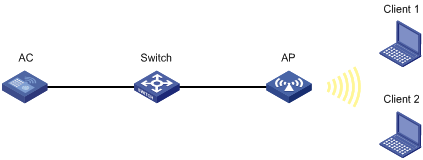
Client rate limiting configuration example
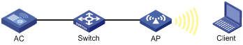
Network requirements
As shown in Figure 41, the AC is in the same network as the AP. Perform the following tasks on the AC:
· Configure static mode client rate limiting to limit the rate of incoming client traffic.
· Configure dynamic mode client rate limiting to limit the rate of outgoing client traffic.
Configuration procedure
1. Click the network view tab at the bottom of the page.
2. Configure a wireless service:
a. From the navigation tree, select Wireless Configuration > Wireless Networks.
b. Add a wireless service:
- Create a wireless service named service.
- Set the SSID to service.
- Enable the wireless service.
3. Configure the AP:
a. From the navigation tree, select AP Management. You are placed on the AP tab.
b. Add and configure AP 1:
- Set the AP name to AP1, select the AP model WA4320i-ACN, and then apply the configuration.
- Click the edit icon in the operation column for AP 1.
- Click the SSID setting tab, and bind the wireless service service to radio 1 of AP 1.
4. Configure client rate limiting:
a. From the navigation tree, select Wireless Configuration > Wireless QoS. You are placed on the Client Rate Limiting tab.
b. Click the more icon in the service configuration area.
c. Select the service name service, and click the edit icon for the wireless service service.
d. On the edit page, perform the following tasks:
- Enable client rate limiting.
- Set the limit mode to static mode for inbound traffic.
- Set the per-client limit rate to 8000 for inbound traffic.
- Set the limit mode to dynamic mode for outbound traffic.
- Set the total limit rate to 8000 for outbound traffic.
5. Enable radio 1 for AP 1:
a. From the navigation tree, select Wireless Configuration > Radio Management. You are placed on the Radio Configuration tab.
b. Click the details icon in the all AP radio configuration area.
c. Select the combination of AP 1 and radio 1, and click the corresponding edit icon.
d. On the edit page, enable radio 1.
Bandwidth guaranteeing configuration example
Network requirements
As shown in Figure 42, Clients 1, 2, and 3 access the network through the SSIDs research, office, and entertain, respectively.
For the network to operate correctly, guarantee 20% of the bandwidth for the SSID office, 80% for research, and none for entertain.
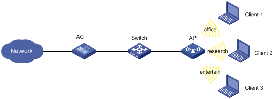
Configuration procedure
1. Click the network view tab at the bottom of the page.
2. Configure a wireless service:
a. From the navigation tree, select Wireless Configuration > Wireless Networks.
b. Add wireless services:
- Create wireless services named office, research, and entertain.
- Set their SSID to office, research, and entertain, respectively.
- Enable the wireless services.
3. Configure the AP:
a. From the navigation tree, select AP Management. You are placed on the AP tab.
b. Add and configure AP 1:
- Set the AP name to AP1, select the AP model WA4320i-ACN, and then apply the configuration.
- Click the edit icon in the operation column for AP 1.
- Click the SSID setting tab, and bind the wireless services office, research, and entertain to radio 1 of AP 1.
4. Configure bandwidth guaranteeing:
a. From the navigation tree, select Wireless Configuration > Wireless QoS.
b. Click the Bandwidth Guaranteeing tab.
c. Click the more icon in the AP configuration area.
d. Select the combination of AP 1 and radio 1, and click the edit icon.
e. On the edit page, perform the following tasks:
- Enable bandwidth guaranteeing.
- Set the guaranteed bandwidth percentage to 20% for the wireless service office.
- Set the guaranteed bandwidth percentage to 80% for the wireless service research.
5. Enable radio 1 for AP 1:
a. From the navigation tree, select Wireless Configuration > Radio Management. You are placed on the Radio Configuration tab.
b. Click the details icon in the all AP radio configuration area.
c. Select the combination of AP 1 and radio 1, and click the corresponding edit icon.
d. On the edit page, enable radio 1.
Verifying the configuration
# View details about AP configuration to verify that the effective bandwidth percentage for each SSID is not greater than the guaranteed bandwidth percentage.
Shared key authentication configuration example
Network requirements
As shown in Figure 43, the switch functions as a DHCP server to assign IP addresses to the AP and client. Configure shared key authentication to enable the client to access the network by using the WEP key 12345.

Configuration procedure
1. Click the network view tab at the bottom of the page.
2. Configure a wireless service:
a. From the navigation tree, select Wireless Configuration > Wireless Networks.
b. Add a wireless service:
- Create a wireless service named service1.
- Set the SSID to service.
- Enable the wireless service.
3. Click Apply and Set Advanced, and then click the Authentication tab.
4. Configure static WEP authentication:
¡ Set the security type to static WEP.
¡ Set the key type to Passphrase.
¡ Select the WEP 40 cipher suite.
¡ Set the key to 12345.
5. Apply the wireless service.
6. Bind the wireless service service1 to the AP:
a. From the navigation tree, select Wireless Configuration > Wireless Networks.
b. Select service1 and click Bind to APs.
c. Select the 5GHz radio of the AP and click Quick Bind.
Verifying the configuration
View details about the wireless service service1 to verify that the configuration is correct.
PSK authentication and bypass authentication configuration example
Network requirements
As shown in Figure 44, the switch functions as a DHCP server to assign IP addresses to the AP and client.
· Configure open system authentication and bypass authentication.
· Configure the client to use the preshared key 12345678 to access the network.
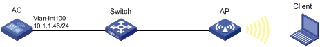
Configuration procedure
1. Click the network view tab at the bottom of the page.
2. Configure a wireless service:
a. From the navigation tree, select Wireless Configuration > Wireless Networks.
b. Add a wireless service:
- Create a wireless service named service1.
- Set the SSID to service.
- Enable the wireless service.
3. Click Apply and Set Advanced, and then click the Authentication tab.
4. Configure static PSK authentication:
¡ Set the security type to static PSK.
¡ Set the security mode to WPA.
¡ Select the CCMP cipher suite.
¡ Set the key type to Passphrase and the key to 12345678.
5. Apply the wireless service.
6. Bind the wireless service service1 to the AP:
a. From the navigation tree, select Wireless Configuration > Wireless Networks.
b. Select service1 and click Bind to APs.
c. Select the 5GHz radio of the AP and click Quick Bind.
Verifying the configuration
View details about the wireless service service1 to verify that the configuration is correct.
PSK authentication and MAC authentication configuration example
Network requirements
As shown in Figure 45, the switch functions as a DHCP server to assign IP addresses to the AP and client.
· Configure open system authentication and MAC authentication for clients.
· Configure the client to use the preshared key 12345678 to access the network.
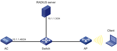
Configuration procedure
1. On the RADIUS server, configure the client's MAC address as the username and password used for authentication. The MAC address cannot contain hyphens and upper case letters.
2. Configure the RADIUS server correctly to provide authentication, authorization, and accounting functions.
3. Configure RADIUS and an authentication domain.
4. Click the network view tab at the bottom of the page.
5. Configure a wireless service:
a. From the navigation tree, select Wireless Configuration > Wireless Networks.
b. Add a wireless service:
- Create a wireless service named service1.
- Set the SSID to service.
- Enable the wireless service.
6. Click Apply and Set Advanced, and then click the Authentication tab.
7. Configure static PSK authentication and MAC authentication:
¡ Set the security type to static PSK and select MAC authentication.
¡ Set the security mode to WPA.
¡ Select the CCMP cipher suite.
¡ Set the key type to Passphrase and the key to 12345678.
¡ Set the domain name to dom1.
8. Apply the wireless service.
9. Bind the wireless service service1 to the AP:
a. From the navigation tree, select Wireless Configuration > Wireless Networks.
b. Select service1 and click Bind to APs.
c. Select the 5GHz radio of the AP and click Quick Bind.
Verifying the configuration
View details about the wireless service service1 to verify that the configuration is correct.
802.1X RADIUS authentication configuration example
Network requirements
As shown in Figure 46, configure the AC to meet the following requirements:
· Use the RADIUS server to perform authentication, authorization, and accounting for 802.1X users.
· Authenticate all 802.1X users who access the AC through GigabitEthernet 1/0/1 in the ISP domain dm1X.
· Use MAC-based access control on GigabitEthernet 1/0/1 to authenticate all 802.1X users on the port separately.
· Exclude domain names from the usernames sent to the RADIUS server.
· Use name as the authentication and accounting shared keys for secure RADIUS communication between the AC and the RADIUS server.
· Use ports 1812 and 1813 for authentication and accounting, respectively.
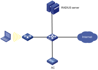
Configuration procedure
1. Assign an IP address to each interface, as shown in Figure 46. (Details not shown.)
2. On the AC, click the system view tab at the bottom of the page.
3. Configure a RADIUS scheme on the AC:
a. From the navigation tree, select Network Security > Authentication.
b. Click the RADIUS tab.
c. Add and configure a RADIUS scheme:
- Set the name of the RADIUS scheme to 802.1X.
- Configure the primary authentication server: set its IP address to 10.1.1.1, set the port number to 1812, set the shared key to name, and set the state to Active.
- Configure the primary accounting server: set its IP address to 10.1.1.1, set the port number to 1813, set the shared key to name, and set the state to Active.
- Set the format of usernames sent to the RADIUS server to Excludes the domain name.
4. Configure an ISP domain on the AC:
a. Click the ISP domains tab.
b. Add and configure an ISP domain:
- Set the domain name to dm1X.
- Set the ISP domain state to Active.
- Set the service type to LAN access.
- Set the method and scheme for authentication, authorization, and accounting to RADIUS and 802.1X, respectively.
5. Configure 802.1X on the AC:
a. From the navigation tree, select Access Control. You are placed on the 802.1X tab.
b. Enable 802.1X globally.
c. Enable 802.1X on GigabitEthernet 1/0/1, and specify MAC-based access control.
d. Access the advanced settings configuration page for GigabitEthernet 1/0/1 to perform the following tasks:
- Set the authorization state to Auto.
- Set the mandatory authentication domain to dm1X.
6. Configure the RADIUS server:
¡ Add a user account on the server. (Details not shown.)
¡ Configure the authentication, authorization, and accounting settings. (Details not shown.)
Verifying the configuration
1. Access the Network Security > Authentication > RADIUS page to verify brief information of the RADIUS scheme 802.1X.
2. Access the Network Security > Authentication > ISP Domains page to verify brief information of the ISP domain dm1X.
3. Verify that the use can come online:
a. Use the configured username and password to log in.
b. Access the Network Security > Access Control > 802.1X page to verify that the number of online users is 1 on GigabitEthernet 1/0/1.
802.1X local authentication configuration example
Network requirements
As shown in Figure 47, add a user account with the username dotuser and password 12345 on the AC. Configure the AC to meet the following requirements:
· Perform local 802.1X authentication to control the network access of users on GigabitEthernet 1/0/1.
· Authenticate the users in the ISP domain abc.
· Specify port-based access control on GigabitEthernet 1/0/1. After a user passes authentication on the port, all subsequent users can access the network without authentication.
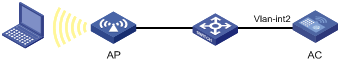
Configuration procedure
1. Assign an IP address to each interface, as shown in Figure 47. (Details not shown.)
2. Click the system view tab at the bottom of the page.
3. Configure a local user:
a. From the navigation tree, select Network Security > User Management. You are placed on the Local Users tab.
b. Add and configure a local user:
- Set the username to dotuser.
- Set the password to 12345.
- Set the service type to LAN access.
4. Configure an ISP domain:
a. From the navigation tree, select Authentication. You are placed on the ISP Domains tab.
b. Add and configure an ISP domain:
- Set the ISP domain name to abc.
- Set the ISP domain state to Active.
- Set the service type to LAN access.
- Configure the ISP domain to use local method for authentication and authorization of LAN users, and not perform accounting for LAN users.
5. Configure 802.1X:
a. From the navigation tree, select Access Control. You are placed on the 802.1X tab.
b. Enable 802.1X globally.
c. Enable 802.1X on GigabitEthernet 1/0/1, and specify port-based access control.
d. Access the advanced settings configuration page for GigabitEthernet 1/0/1 to perform the following tasks:
- Set the authorization state to Auto.
- Set the mandatory authentication domain to abc.
Verifying the configuration
1. Access the Network Security > User Management > Local Users page to verify the configuration of the local user dotuser.
2. Access the Network Security > Authentication > ISP Domains page to verify brief information of the ISP domain abc.
3. Verify that the use can come online:
a. Use the configured username and password to log in.
b. Access the Network Security > Access Control > 802.1X page to verify that the number of online users is 1 on GigabitEthernet 1/0/1.
802.1X AKM configuration example
Network requirements
As shown in Figure 48, the switch functions as a DHCP server to assign IP addresses to the AP and client.
· Configure open system authentication and 802.1X authentication so that the client can access the network by using the login username abcdef and password 123456.
· Configure 802.1X as the AKM mode.
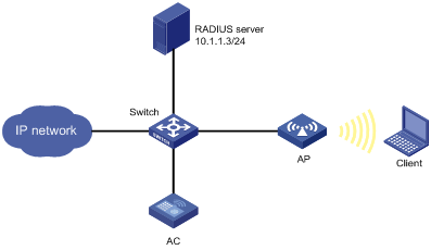
Configuration procedure
1. Configure the username abcdef and the password 123456 on the RADIUS server and make sure the RADIUS server and AC can reach each other. (Details not shown.)
2. Configure RADIUS and an authentication domain.
3. Click the network view tab at the bottom of the page.
4. Configure a wireless service:
a. From the navigation tree, select Wireless Configuration > Wireless Networks.
b. Add a wireless service:
- Create a wireless service named service1.
- Set the SSID to service.
- Enable the wireless service.
5. Click Apply and Set Advanced, and then click the Authentication tab.
6. Configure 802.1X authentication:
¡ Set the security type to 802.1X authentication.
¡ Set the security mode to WPA.
¡ Select the CCMP cipher suite.
¡ Set the domain name to dom1.
7. Apply the wireless service.
8. Bind the wireless service service1 to the AP:
a. From the navigation tree, select Wireless Configuration > Wireless Networks.
b. Select service1 and click Bind to APs.
c. Select the 5GHz radio of the AP and click Quick Bind.
Verifying the configuration
# View details about the wireless service service1 to verify that the configuration is correct.
Direct portal authentication configuration example
Network requirements
As shown in Figure 49, the AP directly forwards user traffic from the client. The client is assigned with a public IP address either manually or through DHCP. A portal server acts as both a portal authentication server and a portal Web server. A RADIUS server acts as the authentication/accounting server.
Configure direct portal authentication, so the client can access only the portal Web server before passing the authentication and access Internet resources after passing the authentication.
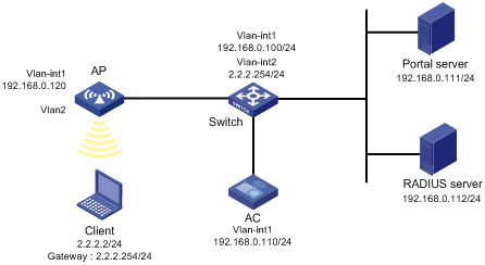
Configuration procedures
1. Configure IP addresses for the client, AC, and servers as shown in Figure 49 and make sure they can reach each other.
2. Configure the RADIUS server correctly to provide authentication and accounting functions.
3. Configure the AP to make sure the AP can communicate with the AC.
4. Configure RADIUS and an authentication domain.
· Configure a wireless service:
a. From the navigation tree, select Wireless Configuration > Wireless Networks.
b. Add a wireless service:
- Create a wireless service named service1.
- Set the SSID to service.
- Enable the wireless service.
5. Configure the portal authentication mode:
a. Click the edit icon for wireless service service1.
The advanced settings page opens.
b. Click the Authentication tab.
c. Select With Portal Authentication.
d. Set the domain name to dm1.
e. Set the server URL to newpt.
f. Set the BAS-IP to 192.168.0.110.
g. Click Apply.
6. Bind the wireless service1 to the AP:
a. From the navigation tree, select Wireless Configuration > Wireless Networks.
b. Select service1 and click Bind to APs.
c. Select the 5GHz radio of the AP and click Bind.
The Bind to AP window opens.
d. Enter 2 in the Bound VLAN field.
e. Click Apply.
Verifying the configuration
# View details about the service service1 to verify that the configuration is correct.
WLAN RRM DFS configuration example
Network requirements
As shown in Figure 50, configure auto-DFS to adjust channels for the APs when a channel adjustment trigger condition is met. Add radio 1 of AP 1 to an RRM holddown group to avoid frequent channel adjustments.
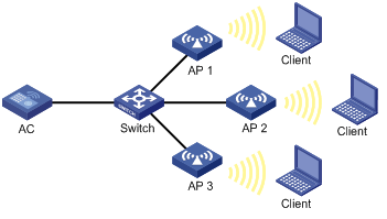
Configuration procedure
1. Click the network view tab at the bottom of the page.
2. Specify a working channel for each AP:
a. From the navigation tree, select Wireless Configuration > Radio Management. You are placed on the Radio Configuration tab.
b. Access the details page for radio configuration and set the working channel to Auto unlock for AP 1, AP 2, and AP 3.
3. Configure auto-DFS:
a. From the navigation tree, select Wireless Configuration > Radio Management.
b. Click the RRM tab.
c. Access the details page for AP configuration to perform the following tasks for AP 1, AP 2, and AP 3:
- Enable auto-DFS.
- Set the tolerance level, CRC error threshold, and interference threshold to 25, 30, and 60, respectively.
d. Access the details page for RRM holddown group configuration to perform the following tasks:
- Create RRM holddown group 10.
- Set the channel holddown time to 600 minutes.
e. Add the 5 GHz radio of AP 1 to RRM holddown group 10.
Verifying the configuration
# On the Monitoring > RF Monitoring > RRM page, verify the following information:
· The working channels for the APs change when a channel adjustment trigger condition is met and the calibration interval is reached.
· The channel for radio 1 on AP 1 remains unchanged within 600 minutes after the first DFS.
WLAN RRM TPC configuration example
Network requirements
As shown in Figure 51, configure auto-TPC and set the neighbor number threshold as 3 to enable the AC to perform auto-TPC when AP 4 joins. Add radio 1 of AP 1 to an RRM holddown group to avoid frequent power adjustments.
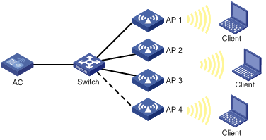
Configuration procedure
1. Click the network view tab at the bottom of the page.
2. Disable power lock for the APs:
a. From the navigation tree, select Wireless Configuration > Radio Management. You are placed on the Radio Configuration tab.
b. Access the details page for radio configuration to disable power lock for AP 1, AP 2, AP 3, and AP 4.
3. Configure auto-TPC:
a. From the navigation tree, select Wireless Configuration > Radio Management.
b. Click the RRM tab.
c. Access the details page for AP configuration to perform the following tasks for AP 1, AP 2, AP 3, and AP 4:
- Enable auto-TPC.
- Set the TPC mode to Custom.
- Set the adjacency factor, power adjustment threshold, and minimum transmit power to 3, ‑70 dBm, and 5 dBm, respectively.
d. Access the details page for RRM holddown group configuration to perform the following tasks:
- Create RRM holddown group 10.
- Set the power holddown time to 100 minutes.
e. Add the 5 GHz radio of AP 1 to RRM holddown group 10.
Verifying the configuration
# On the Monitoring > RF Monitoring > RRM page, verify the following information:
· The power values for the APs change when the power adjustment threshold and the calibration interval are reached.
· The power for radio 1 on AP 1 remains unchanged within 100 minutes after the first TPC.
Session-mode load balancing configuration example for radios
Network requirements
As shown in Figure 52, AP 1 and AP 2 are managed by the AC and the clients can discover the APs.
Configure the AC to perform session-mode load balancing on AP 1 and AP 2 when the following conditions are met:
· The number of sessions on one AP reaches 3.
· The session gap between the APs reaches 2.
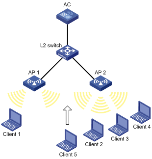
Configuration procedure
1. Click the network view tab at the bottom of the page.
2. Configure a wireless service:
a. From the navigation tree, select Wireless Configuration > Wireless Networks.
b. Add a wireless service:
- Create a wireless service named service.
- Set the SSID to session-balance.
- Enable the wireless service.
3. Configure the APs:
a. From the navigation tree, select AP Management. You are placed on the AP tab.
b. Add and configure AP 1:
- Set the AP name to AP1, select the AP model WA4320i-ACN, and then apply the configuration.
- Click the edit icon in the operation column for AP 1.
- Click the SSID setting tab, and bind the wireless service service to the radio of AP 1.
c. Add and configure AP 2 in the same way AP 1 is added and configured.
4. Configure load balancing:
a. From the navigation tree, select Wireless Configuration > Radio Management.
b. Click the Load Balancing tab.
c. Access the details page for global configuration to perform the following tasks:
- Enable load balancing.
- Select Session Mode.
- Set the session threshold to 3 and the session gap to 2.
Verifying the configuration
# Verify that the AC performs session-mode load balancing for AP 1 and AP 2 when the following conditions are met:
· The number of sessions on one AP reaches 3.
· The session gap between the APs reaches 2.
# On the Monitoring > Clients page, verify that AP 1 and AP 2 are load balanced.
Traffic-mode load balancing configuration example for radios
Network requirements
As shown in Figure 53, AP 1 and AP 2 are managed by the AC and the clients can discover the APs. The maximum bandwidth for each AP is 150 Mbps.
Configure the AC to perform traffic-mode load balancing on AP 1 and AP 2 when the following conditions are met:
· The traffic on one AP reaches 30 Mbps (20% of the maximum bandwidth).
· The traffic gap between the APs reaches 15 Mbps (10% of the maximum bandwidth).
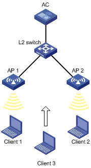
Configuration procedure
1. Click the network view tab at the bottom of the page.
2. Configure a wireless service:
a. From the navigation tree, select Wireless Configuration > Wireless Networks.
b. Add a wireless service:
- Create a wireless service named service.
- Set the SSID to traffic-balance.
- Enable the wireless service.
3. Configure the APs:
a. From the navigation tree, select AP Management. You are placed on the AP tab.
b. Add and configure AP 1:
- Set the AP name to AP1, select the AP model WA4320i-ACN, and then apply the configuration.
- Click the edit icon in the operation column for AP 1.
- Click the SSID setting tab, and bind the wireless service service to the radio of AP 1.
c. Add and configure AP 2 in the same way AP 1 is added and configured.
4. Configure load balancing:
a. From the navigation tree, select Wireless Configuration > Radio Management.
b. Click the Load Balancing tab.
c. Access the details page for global configuration to perform the following tasks:
- Enable load balancing.
- Select Traffic Mode.
- Set the traffic threshold to 20 and the traffic gap to 10.
Verifying the configuration
# Verify that the AC performs session-mode load balancing for AP 1 and AP 2 when the following conditions are met:
· The traffic of one AP reaches 30 Mbps.
· The traffic gap between the APs reaches 15 Mbps.
# On the Monitoring > Clients page, verify that AP 1 and AP 2 are load balanced.
Bandwidth-mode load balancing configuration example for radios
Network requirements
As shown in Figure 54, AP 1 and AP 2 are managed by the AC and the clients can discover the APs.
Configure the AC to perform bandwidth-mode load balancing on AP 1 and AP 2 when the following conditions are met:
· The bandwidth of one AP reaches 12 Mbps.
· The bandwidth gap between the APs reaches 3 Mbps.

Configuration procedure
1. Click the network view tab at the bottom of the page.
2. Configure a wireless service:
a. From the navigation tree, select Wireless Configuration > Wireless Networks.
b. Add a wireless service:
- Create a wireless service named service.
- Set the SSID to bandwidth-balance.
- Enable the wireless service.
3. Configure the APs:
a. From the navigation tree, select AP Management. You are placed on the AP tab.
b. Add and configure AP 1:
- Set the AP name to AP1, select the AP model WA4320i-ACN, and then apply the configuration.
- Click the edit icon in the operation column for AP 1.
- Click the SSID setting tab, and bind the wireless service service to the radio of AP 1.
c. Add and configure AP 2 in the same way AP 1 is added and configured.
4. Configure load balancing:
a. From the navigation tree, select Wireless Configuration > Radio Management.
b. Click the Load Balancing tab.
c. Access the details page for global configuration to perform the following tasks:
- Enable load balancing.
- Select Bandwidth Mode.
- Set the bandwidth threshold to 12 and the bandwidth gap to 3.
Verifying the configuration
# Verify that the AC performs bandwidth-mode load balancing for AP 1 and AP 2 when the following conditions are met:
· The bandwidth of one AP reaches 12 Mbps.
· The bandwidth gap between the APs reaches 3 Mbps.
# On the Monitoring > Clients page, verify that AP 1 and AP 2 are load balanced.
Session-mode load balancing configuration example for a load balancing group
Network requirements
As shown in Figure 55, AP 1, AP 2, and AP 3 are managed by the AC and the clients can discover the APs.
Configure the AC to perform session-mode load balancing on radio 2 of AP 1 and radio 2 of AP 2 when the following conditions are met:
· The number of sessions on one radio reaches 3.
· The session gap between the radios reaches 2.
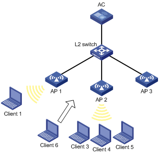
Configuration procedure
1. Click the network view tab at the bottom of the page.
2. Configure a wireless service:
a. From the navigation tree, select Wireless Configuration > Wireless Networks.
b. Add a wireless service:
- Create a wireless service named service.
- Set the SSID to session-balance.
- Enable the wireless service.
3. Configure the APs:
a. From the navigation tree, select AP Management. You are placed on the AP tab.
b. Add and configure AP 1:
- Set the AP name to AP1, select the AP model WA4320i-ACN, and then apply the configuration.
- Click the edit icon in the operation column for AP 1.
- Click the SSID setting tab, and bind the wireless service service to the radio of AP 1.
c. Add and configure AP 2 and AP 3 in the same way AP 1 is added and configured.
4. Configure load balancing:
a. From the navigation tree, select Wireless Configuration > Radio Management.
b. Click the Load Balancing tab.
c. Access the details page for global configuration to perform the following tasks:
- Enable load balancing.
- Select Session Mode.
- Set the session threshold to 3 and the session gap to 2.
d. Access the details page for load balancing group configuration to perform the following tasks:
- Create a load balancing group.
- Bind radio 2 of AP 1 and AP 2 to the load balancing group.
Verifying the configuration
# Verify that the AC performs session-mode load balancing for radio 2 of AP 1 and radio 2 of AP 2 when the following conditions are met:
· The number of sessions on one radio reaches 3.
· The session gap between the radios reaches 2.
# On the Monitoring > Clients page, verify that AP 1 and AP 2 are load balanced.
Traffic-mode load balancing configuration example for a load balancing group
Network requirements
As shown in Figure 56, AP 1, AP 2, and AP 3 are managed by the AC and the clients can discover the APs. The maximum bandwidth for each AP is 150 Mbps.
Configure the AC to perform traffic-mode load balancing on radio 2 of AP 1 and radio 2 of AP 2 when the following conditions are met:
· The traffic of one radio reaches 30 Mbps (20% of the maximum bandwidth).
· The traffic gap between the radios reaches 15 Mbps (10% of the maximum bandwidth).

Configuration procedure
1. Click the network view tab at the bottom of the page.
2. Configure a wireless service:
a. From the navigation tree, select Wireless Configuration > Wireless Networks.
b. Add a wireless service:
- Create a wireless service named service.
- Set the SSID to traffic-balance.
- Enable the wireless service.
3. Configure the APs:
a. From the navigation tree, select AP Management. You are placed on the AP tab.
b. Add and configure AP 1:
- Set the AP name to AP1, select the AP model WA4320i-ACN, and then apply the configuration.
- Click the edit icon in the operation column for AP 1.
- Click the SSID setting tab, and bind the wireless service service to the radio of AP 1.
c. Add and configure AP 2 and AP 3 in the same way AP 1 is added and configured.
4. Configure load balancing:
a. From the navigation tree, select Wireless Configuration > Radio Management.
b. Click the Load Balancing tab.
c. Access the details page for global configuration to perform the following tasks:
- Enable load balancing.
- Select Traffic Mode.
- Set the traffic threshold to 20 and the traffic gap to 10.
d. Access the details page for load balancing group configuration to perform the following tasks:
- Create a load balancing group.
- Bind radio 2 of AP 1 and AP 2 to the load balancing group.
Verifying the configuration
# Verify that the AC performs traffic-mode load balancing for radio 2 of AP 1 and radio 2 of AP 2 when the following conditions are met:
· The traffic of one radio reaches 30 Mbps.
· The traffic gap between the radios reaches 15 Mbps.
# On the Monitoring > Clients page, verify that AP 1 and AP 2 are load balanced.
Bandwidth-mode load balancing configuration example for a load balancing group
Network requirements
As shown in Figure 57, AP 1, AP 2, and AP 3 are managed by the AC and the clients can discover the APs.
Configure the AC to perform bandwidth-mode load balancing on radio 2 of AP 1 and radio 2 of AP 2 when the following conditions are met:
· The bandwidth of one radio reaches 12 Mbps.
· The bandwidth gap between the radios reaches 3 Mbps.
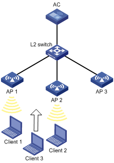
Configuration procedure
1. Click the network view tab at the bottom of the page.
2. Configure a wireless service:
a. From the navigation tree, select Wireless Configuration > Wireless Networks.
b. Add a wireless service:
- Create a wireless service named service.
- Set the SSID to bandwidth-balance.
- Enable the wireless service.
3. Configure the APs:
a. From the navigation tree, select AP Management. You are placed on the AP tab.
b. Add and configure AP 1:
- Set the AP name to AP1, select the AP model WA4320i-ACN, and then apply the configuration.
- Click the edit icon in the operation column for AP 1.
- Click the SSID setting tab, and bind the wireless service service to the radio of AP 1.
c. Add and configure AP 2 and AP 3 in the same way AP 1 is added and configured.
4. Configure load balancing:
a. From the navigation tree, select Wireless Configuration > Radio Management.
b. Click the Load Balancing tab.
c. Access the details page for global configuration to perform the following tasks:
- Enable load balancing.
- Select Bandwidth Mode.
- Set the bandwidth threshold to 12 and the bandwidth gap to 3.
d. Access the details page for load balancing group configuration to perform the following tasks:
- Create a load balancing group.
- Bind radio 2 of AP 1 and AP 2 to the load balancing group.
Verifying the configuration
# Verify that the AC performs bandwidth-mode load balancing for radio 2 of AP 1 and radio 2 of AP 2 when the following conditions are met:
· The bandwidth of one radio reaches 12 Mbps.
· The bandwidth gap between the radios reaches 3 Mbps. (Details not shown.)
# On the Monitoring > Clients page, verify that AP 1 and AP 2 are load balanced.
Band navigation configuration example
Network requirements
As shown in Figure 58, both the 5 GHz radio and the 2.4 GHz radio are enabled on the AP. Configure band navigation and load balancing for band navigation to load balance the radios.
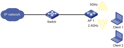
Configuration procedure
1. Click the network view tab at the bottom of the page.
2. Configure a wireless service:
a. From the navigation tree, select Wireless Configuration > Wireless Networks.
b. Access the page for adding a wireless network to perform the following tasks:
- Set the name of the wireless service to service.
- Set its SSID to band-navigation.
- Disable fast association.
- Enable the wireless service.
3. Configure AP 1:
a. From the navigation tree, select Wireless Configuration > AP Management.
b. Click the AP tab.
c. Access the configuration page for AP 1 and click the SSID tab.
d. Bind the wireless service service to both the 5 GHz and 2.4 GHz radios of AP 1.
4. Configure band navigation:
a. From the navigation tree, select Wireless Configuration > Radio Management.
b. Click the Band Navigation tab.
c. Access the details page for global configuration to perform the following tasks:
- Enable band navigation globally.
- Set the session threshold to 5.
- Set the session gap threshold to 2.
d. Access the band navigation configuration page for AP 1 to enable band navigation for AP 1.
Verifying the configuration
# On the Monitoring > Clients page, verify that the 5 GHz radio and the 2.4 GHz radio of AP 1 are load balanced.
Wireless locating configuration example
Network requirements
As shown in Figure 59, configure wireless locating on AP 1, AP 2, and AP 3 to locate the MU and the Tag.
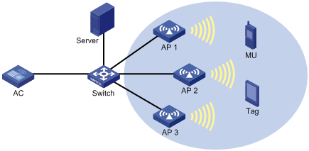
Configuration procedure
1. Configure the locating server:
¡ Set the IP addresses of the three APs on the locating server, or configure the locating server to discover APs through broadcast. (Details not shown.)
¡ Configure wireless locating on the locating server. (Details not shown.)
2. Click the network view tab at the bottom of the page.
3. Configure a wireless service:
a. From the navigation tree, select Wireless Configuration > Wireless Networks.
b. Access the page for adding a wireless service to perform the following tasks:
- Set the wireless service name to market.
- Enable the wireless service.
4. Configure AP 1:
a. From the navigation tree, select Wireless Configuration > AP Management. You are placed on the AP tab.
b. Access the page for adding an AP to perform the following tasks:
- Set the AP name to AP1.
- Select the AP model WA4320i-ACN.
- Set the serial ID.
c. Click the edit icon in the operation column for AP 1 to perform the following tasks:
- Click the SSID tab.
- Bind the wireless service market to radio 1 of the AP AP1.
d. From the navigation tree, select Wireless Configuration > Applications.
e. Click the Location Aware tab.
f. Access the details page for global configuration.
g. Click the Aeroscout configuration tab.
h. Enable Aeroscout locating.
i. Access the details page for AP configuration to perform the following tasks:
- Access the edit page for the AP AP1. You are placed on the Common tab.
- Enable ignoring beacon frames.
- Click the Aeroscout tab.
- Enable AeroScout locating.
- Enable radio 1.
- Select both the MU and Tag.
5. Configure AP 2 and AP 3 in the same way AP 1 is configured.
Verifying the configuration
# Verify that you can view the locating information about the MU and the Tag by using maps, forms, or reports provided by the graphics software. (Details not shown.)
Network security configuration examples
BYOD configuration example
Network requirements
As shown in Figure 60, perform the following tasks for the AC to perform 802.1X authentication on the client:
· Set the username and password for 802.1X authentication to dotuser and 12345, respectively.
· Set the authentication method to open system for the AC to perform local authentication and authorization for the client, and set the authentication domain name to abc.
· Allow the client that runs Microsoft Windows 8 to access VLAN 3 after passing the authentication.
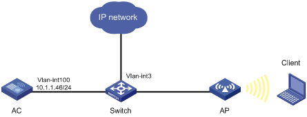
Configuration procedure
1. Assign an IP address to each interface. (Details not shown.)
2. Click the network view tab at the bottom of the page.
3. Configure a wireless service:
a. From the navigation tree, select Wireless Configuration > Wireless Networks.
b. Access the page for adding a wireless service to perform the following tasks:
- Set the wireless service name to service1.
- Set the SSID to service.
- Enable the wireless service.
4. Configure 802.1X:
a. From the navigation tree, select Wireless Configuration > Wireless Networks.
b. Access the advanced settings configuration page for the wireless service service1 to perform the following tasks:
- Set the security type to 802.1X authentication.
- Set the security mode to WPA.
- Select the CCMP cipher suite.
- Set the domain name.
5. Bind the wireless service to the AP:
a. From the navigation tree, select Wireless Configuration > Wireless Networks.
b. Select the wireless service service1, and click the bind to APs button.
c. Select the 5 GHz radio of the AP, and then click the quick bind button.
6. Configure an ISP domain:
a. From the navigation tree, select Network Security > Authentication. You are placed on the ISP Domains tab.
b. Add an ISP domain, and then set its state to active.
c. Set the service type to LAN Access.
d. Set the authentication, authorization, and accounting methods to Local, Local, and None, respectively.
7. Configure a local user:
a. From the navigation tree, select Network Security > User Management. You are placed on the Local Users tab.
b. Click User groups.
c. Click the add icon.
d. Add a user group named windows8.
e. Click Apply.
f. On the Local Users tab, click Users.
g. Click the add icon.
h. Add a user named dotuser, and then set the password to 12345.
i. Set the service type to LAN Access.
j. Specify the user group windows8.
k. Click Apply.
8. Configure BYOD authorization:
a. From the navigation tree, select Network Security > BYOD.
b. Click the BYOD Authorization tab.
c. Set the terminal type to Microsoft Windows 8.
d. Set the ACL number to 2000.
e. Set the authorization VLAN to VLAN 3.
f. Click Apply.
9. Configure BYOD rules:
a. From the navigation tree, select Network Security > BYOD. You are placed on the BYOD Rules tab.
b. Add a DHCP rule:
- Set the DHCP Option 55 value to 1,15,3,6,44,46,47,31,33,121,249,252,43.33.
- Set the terminal type to Microsoft Windows 8.
Verifying the configuration
# Verify that the client can access the resources in VLAN 3 after passing 802.1X authentication.
Guest management configuration example
Network requirements
Configure guest management on the AC as follows:
· Create a guest account user1 for Jack, and set the password, user group, personal profiles, validity period, and receptionist information.
· Configure the SMTP server address, sender address, and guest administrator's email address that are used to send emails.
· Configure the subject and contents of the Emails to be sent to the guest, receptionist, and guest administrator.
· Configure the system to automatically delete expired guest accounts.
Figure 61 Network diagram
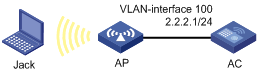
Configuration procedures
1. Configure IP addresses for interfaces. (Details not shown.)
2. Configure wireless services. (Details not shown.)
3. Add a guest account:
a. Click the network view tab at the bottom of the page.
b. From the navigation tree, select Network Security > Guest Management.
c. On the Guest List tab, click the add icon.
d. On the Add Guest page, perform the following tasks:
- Set the account and password to user1 and 123456, respectively.
- Select a group for the guest.
- Enter the full name, company, Email address, phone number, and description of the guest.
- Enter the sponsor's full name, department, and Email address.
- Set the validity period.
4. Configure the guest service parameters:
a. Click the network view tab at the bottom of the page.
b. From the navigation tree, select Network Security > Guest Management.
c. Click the Guest Configuration tab.
d. Select Auto delete.
e. Set the SMTP server address to smtp://192.168.0.112/smtp.
f. Set the email sender address to [email protected].
g. Set the guest manager email address to [email protected].
h. Set the subject of notifications to guests to Guest account information, and set the body to A guest account has been created for your use. The username, password, and valid dates for the account are given below..
i. Set the subject of notifications to guest managers to Guest register information, and set the body to A guest account has been registered. The username for the account is given below. Please approve the register information..
j. Set the subject of notifications to guest sponsors to Guest account information, and set the body to A guest account has been created. The username, password, and valid dates for the account are given below..
Verifying the configuration
# Verify that guest Jack can access the network after passing local authentication by using username user1 and password 123456.
Tools configuration examples
Local packet capture configuration example
Network requirements
As shown in Figure 62, enable local packet capture on radio 1 of the AP to capture 1 KB of TCP packets sourced from 192.168.20.173. The switch acts as the FTP server for storing the captured packets sent by the AP.
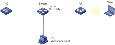
Configuration procedure
1. Configure the switch:
a. Create a device management user named abc.
b. Set the password for the user to 123456.
c. Specify the user role for the user as network-admin.
d. Specify the working directory flash:/ for the user.
e. Specify the service type for the user as ftp.
f. Enable the FTP server on the switch.
2. Configure local packet capture:
a. Click the network view tab at the bottom of the page.
b. From the navigation tree, select Tools > Wireless Capture.
c. Select radio 1 of the AP.
d. Configure wireless capture:
- Select the local packet capture mode.
- Specify the capture filter as src 192.168.20.173 and tcp.
- Set the maximum frame size to 8000 bytes.
- Set the file size to 1 KB.
- Set the FTP URL to ftp://10.1.1.1.
- Set the FTP username to abc.
- Set the FTP password to 123456.
Verifying the configuration
# Verify that the captured packets can be displayed on the PC after the Wireshark client is connected to the FTP server.
Remote packet capture configuration example
Network requirements
As shown in Figure 63, enable remote packet capture on radio 1 of the AP and use Wireshark to display the captured packets.
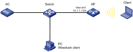
Configuration procedure
1. Configure remote packet capture:
a. Click the network view tab at the bottom of the page.
b. From the navigation tree, select Tools > Wireless Capture.
c. Select radio 1 of the AP.
d. Select the remote packet capture mode.
e. Set the RPCAP port to 2014.
2. Display captured packets on the PC:
a. Start Wireshark and select Capture > Options.
b. Select Remote from the Interface list.
c. Enter the IP address 10.1.1.1 and the port number 2014, and click OK.
d. Click Start.
The captured packets are displayed on the page that appears.
Figure 64 Displaying the captured packets on the Wireshark