- Table of Contents
- Related Documents
-
| Title | Size | Download |
|---|---|---|
| 04-SIP configuration | 523.90 KB |
Transport protocols supported by SIP
Restrictions: Hardware compatibility with SIP
Restrictions: Licensing requirements for SIP
Configuring SIP UA registration
About the process of SIP registration
Prerequisites for configuring SIP UA registration
Enabling a POTS entity to register with the registrar
Configuring the call destination address for a VoIP entity
About configuration approaches
Configuring the call destination IP address for a VoIP entity
Configuring a VoIP entity to obtain the call destination address from a proxy server
Configuring the destination domain name and port number for a VoIP entity
Configuring out-of-dialog keepalive for a VoIP entity
Configuring INVITE retransmission
Configuring extended SIP functions
Configuring source interface binding for outgoing SIP messages or media packets
Configuring out-of-band DTMF signaling
Configuring SIP session refresh
Configuring in-dialog keepalive
Configuring PSTN cause-to-SIP status mappings
Setting the P-Asserted-Identity or P-Preferred-Identity header field
Configuring reliable provisional responses
Enabling early media negotiation
Configuring transport protocols for SIP calls
Restrictions and guidelines for configuring transport protocols
Configuring UDP or TCP for outgoing SIP calls
Enabling the UDP or TCP listening port
Setting the aging time for TCP connections
Configuring TLS as the transport protocol
Configuring SRTP for SIP calls
Restrictions and guidelines for specifying a URL scheme
Specifying a global URL scheme for outgoing SIP calls
Specifying a URL scheme for outgoing SIP calls on a VoIP entity
Configuring QSIG tunneling over SIP-T
Display and maintenance commands for SIP
Example: Configuring direct SIP calling
Example: Configuring SIP calling through a SIP server
Example: Configuring SIP calling through DNS
Example: Configuring SIP to use TCP as the transport protocol
Example: Configuring SIP to use TLS as the transport protocol
Example: Configuring out-of-band DTMF signaling
Restrictions: Hardware compatibility with SIP trunk
Restrictions: Licensing requirements for SIP trunk
Configuring a SIP trunk account
Enabling codec transparent transmission
Display and maintenance commands for SIP trunk
SIP trunk configuration examples
Example: Configuring SIP trunk
Configuring SIP
About SIP
Session Initiation Protocol (SIP) is an application layer control protocol that can create, modify, and terminate multimedia sessions such as voice and video calls over IP networks.
Similar to HTTP, SIP is a text-based protocol, which is easy to implement and extend. With the capacity for signaling control, SIP is applicable to Internet-based multimedia communication systems (such as telecom, banking, and financial systems) to provide value-added services.
SIP network elements
SIP uses the client/server model to implement user calls. The SIP client is a user agent, and SIP servers include proxy server, redirection server, location server, and registrar.
User agent
A user agent (UA) is a SIP endpoint such as a phone, a gateway, or a router.
There are two types of UAs: user agent client (UAC) and user agent server (UAS). A UAC sends SIP requests, and a UAS receives SIP requests and returns SIP responses. These roles of UAC and UAS only last for the duration of a SIP transaction.
Proxy server
A proxy server primarily forwards session requests and responses. It can also provide call control, accounting, and authorization functions.
Redirect server
A redirect server sends new addresses to UACs so the UAC sends session requests to the new addresses.
Location server
A location server provides UA information to proxy and redirect servers.
Registrar
A registrar receives registrations from UAs and generates UA information. The UA information is stored on the location server.
SIP functions
SIP supports the following facets of establishing and terminating multimedia communications:
· User location—Determines the end system to be used for communication. SIP can use UA information on the registrar or use information provided by DNS or LDAP to locate end systems.
· User availability—Determines the willingness of the called party to engage in communications.
· User capabilities—Determines the media type and media parameters to be used. In a message exchange process, each SIP endpoint advertises media information so that all other participants can learn about its capabilities.
· Session establishment—Establishes session parameters at both called and calling parties.
· Session management—Transfers and terminates sessions, modifies session parameters, and invokes services.
SIP messages
SIP is a text-based protocol. A SIP message is either a request from a client to a server, or a response from a server to a client.
SIP requests include INVITE, ACK, OPTIONS, BYE, CANCEL, and REGISTER.
· INVITE—Invites a user to join a call.
· ACK—Acknowledges the response to a request.
· OPTIONS—Queries for the capabilities.
· BYE—Releases an established call.
· CANCEL—Gives up a call attempt.
· REGISTER—Registers with the SIP registrar.
SIP responses indicate the status of a call or registration. Responses are distinguished by status codes. As shown in Table 1, each status code is a 3-digit integer, where the first digit defines the class of the response, and the last two digits describe the response message in more detail.
Table 1 Status codes of responses
|
Code |
Description |
Class |
|
100–199 |
The request was received and is being processed. |
Provisional |
|
200–299 |
The request was successfully received, understood, and accepted. |
Success |
|
300–399 |
A further action must be taken to complete the request. |
Redirection |
|
400–499 |
The request contains bad syntax or cannot be fulfilled at this server. |
Client failure |
|
500–599 |
The server failed to fulfill an apparently valid request. |
Server failure |
|
600–699 |
The request cannot be fulfilled at any server. |
Global failure |
Transport protocols supported by SIP
SIP supports the following transport protocols:
· UDP—Connectionless and unreliable. SIP connections over UDP are unreliable.
· TCP—Connection-oriented and reliable. TCP solves packet loss and retransmission issues for SIP messages and voice packets. SIP also supports Transport Layer Security (TLS) over TCP. TLS over TCP provides security for SIP messages. For more information, see "Signaling authentication and encryption."
The choice of the transport protocol depends on the actual application environment.
SIP security
SIP can use TLS and SRTP to secure SIP messages (user information) and media packets (the contents of calls), respectively. TLS and SRTP can be used separately or together. As a best practice, enable both TLS and SRTP.
Signaling authentication and encryption
TLS over TCP provides a security solution for mutual authentication and encryption. The two communication parties authenticate each other by using digital certificates before establishing a TLS connection. SIP messages are encrypted over the TLS connection. For more information about TLS, see "Configuring TLS as the transport protocol." To use TLS for SIP, you must also configure TLS security policies (see Security Configuration Guide).
Media authentication and encryption
SIP supports two media stream protocols: Real-Time Transport Protocol (RTP) and Real-Time Transport Control Protocol (RTCP). RTP provides end-to-end transmission for real-time data, such as interactive voice and video. RTCP monitors transmission quality and provides congestion control and flow control. RTP and RTCP work together to achieve optimal transmission efficiency by providing efficient feedback and minimizing overheads.
Secure Real-Time Transport Protocol (SRTP) enhances RTP by encrypting RTP/RTCP packets and providing authentication and retransmission. For information about configuring media stream protocols for SIP, see "Configuring SRTP for SIP calls."
SRTP requires encryption negotiation. The device supports encryption negotiation only through the crypto headers in the Session Description Protocol (SDP). The initiator of negotiation sends its encryption attributes to the peer, and the peer returns the attributes if it accepts them. Each party encrypts and decrypts RTP/RTCP packets by using the negotiated key.
Table 2 Negotiation attributes
|
Attribute |
Description |
Remarks |
|
Tag |
Identifies a particular cryptographic attribute to determine which of the offered cryptographic attributes was chosen by the receiver. |
Mandatory. |
|
Crypto-Suite |
Defines the encryption and authentication algorithms. The device only supports the AES_CM_128_HMAC_SHA1_80 and AES_CM_128_HMAC_SHA1_32 suites. |
Mandatory. |
|
Key Parameters |
Includes the key generation method and key value. |
Mandatory. |
|
Session Parameters |
Includes the key derivation rate, UNENCRYPTED_SRTP, UNENCRYPTED_SRTCP, UNAUTHENTICATED_SRTP, and FEC. |
Optional; not supported. |
Crypto engine for SIP
Signaling/media authentication and encryption can be implemented by software or hardware.
· Software implementation—Complex authentication and encryption/decryption algorithms consume excessive CPU resources and affect overall device processing efficiency.
· Hardware implementation—Complex algorithms are processed by the hardware crypto engine and have no impact on device processing efficiency. The device sends the data to the hardware crypto engine. After the crypto engine completes data encryption/decryption, it sends the data back to the device.
For more information about crypto engines, see Security Configuration Guide.
Restrictions: Hardware compatibility with SIP
|
Hardware |
SIP compatibility |
|
MSR810, MSR810-W, MSR810-W-DB, MSR810-LM, MSR810-W-LM, MSR810-10-PoE, MSR810-LM-HK, MSR810-W-LM-HK, MSR810-LMS-EA |
MSR810, MSR810-W, MSR810-W-DB, MSR810-LM, MSR810-W-LM, MSR810-10-PoE, MSR810-LM-HK, MSR810-W-LM-HK: Yes MSR810-LMS-EA: No |
|
MSR810-LMS, MSR810-LUS |
No |
|
MSR2600-6-X1 |
No |
|
MSR2600-10-X1 |
Yes |
|
MSR 2630 |
Yes |
|
MSR3600-28, MSR3600-51 |
Yes |
|
MSR3600-28-SI, MSR3600-51-SI |
No |
|
MSR3600-28-X1, MSR3600-28-X1-DP, MSR3600-51-X1, MSR3600-51-X1-DP |
No |
|
MSR3610-I-DP, MSR3610-IE-DP |
No |
|
MSR3610-X1, MSR3610-X1-DP, MSR3610-X1-DC, MSR3610-X1-DP-DC |
Yes |
|
MSR 3610, MSR 3620, MSR 3620-DP, MSR 3640, MSR 3660 |
Yes |
|
MSR3610-G, MSR3620-G |
No |
Restrictions: Licensing requirements for SIP
To support SIP, some device models require the Voice Software License. For more information, see license management in Fundamentals Configuration Guide.
SIP tasks at a glance
To configure SIP, perform the following tasks:
1. Configuring SIP UA registration
a. (Optional.) Configuring SIP credentials
b. Enabling a POTS entity to register with the registrar
2. Configuring the call destination address for a VoIP entity
Use one of the following methods.
¡ Configuring the call destination IP address for a VoIP entity
¡ Configuring a VoIP entity to obtain the call destination address from a proxy server
¡ Configuring the destination domain name and port number for a VoIP entity
3. (Optional.) Configuring out-of-dialog keepalive for a VoIP entity
4. (Optional.) Configuring INVITE retransmission
5. (Optional.) Configuring a trusted node
6. (Optional.) Configuring extended SIP functions
¡ Configuring source interface binding for outgoing SIP messages or media packets
¡ Configuring out-of-band DTMF signaling
¡ Configuring SIP session refresh
¡ Configuring in-dialog keepalive
¡ Configuring PSTN cause-to-SIP status mappings
¡ Setting the P-Asserted-Identity or P-Preferred-Identity header field
¡ Configuring reliable provisional responses
¡ Enabling SIP support for VRF
¡ Configuring a SIP domain name
¡ Configuring SIP compatibility
¡ Enabling early media negotiation
7. (Optional.) Configuring transport protocols for SIP calls
¡ Configuring UDP or TCP for outgoing SIP calls
¡ Enabling the UDP or TCP listening port
¡ Setting the aging time for TCP connections
8. (Optional.) Configuring SIP security
¡ Configuring TLS as the transport protocol
¡ Configuring SRTP for SIP calls
¡ Specifying a global URL scheme for outgoing SIP calls
¡ Specifying a URL scheme for outgoing SIP calls on a VoIP entity
10. (Optional.) Setting the global DSCP value
11. (Optional.) Configuring QSIG tunneling over SIP-T
Configuring SIP UA registration
About the process of SIP registration
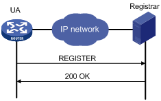
A SIP UA registers with a SIP registrar as shown in Figure 1.
1. The SIP UA sends a REGISTER request to the registrar.
2. The registrar returns a 200 OK response to the UA if the registration is accepted.
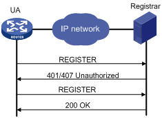
If the registrar needs to authenticate the UA, the UA registers with the registrar as shown in Figure 2.
1. The UA sends a REGISTER request to the registrar.
2. The registrar returns a 401/407 response, challenging the originator to provide credentials.
3. The UA sends a REGISTER request that includes credentials to the registrar.
4. The registrar returns a 200 OK response to the UA if the authentication succeeds.
Figure 2 Registration process with authentication
Prerequisites for configuring SIP UA registration
Complete the following tasks before you configure SIP credentials information:
· Configure a number template on each voice entity by using the match-template command. Bind each voice entity to a voice interface by using the line command.
· Enable the voice entities and voice interfaces (in undo shutdown state).
Configuring SIP credentials
About SIP credentials
If the registrar provides UA authentication, configure SIP credentials on the SIP UA in the following ways:
· Use the user command in SIP view to configure global SIP credentials.
· Use the credentials command to configure SIP credentials for a SIP trunk account. For more information about SIP trunk, see "Configuring SIP trunk."
· Use the user command in voice entity view to configure SIP credentials for a voice entity.
Restrictions and guidelines
· A SIP UA can register with up to six registrars, and it uses the realm in the 401/407 response from a registrar to identify the credentials to be sent to the registrar.
You can configure only one username by using the user command in SIP view or voice entity view. The username can contain 12 credentials bindings. A binding that does not include a realm can be used to respond to a 401/407 response that does not match any realm-included binding. The following example configures four credentials bindings:
[Sysname-voice-dial-entity100] user 1000 password simple 1000 realm server1
[Sysname-voice-dial-entity100] user 1000 password simple 1000 realm server2
[Sysname-voice-dial-entity100] user 1000 password simple 2000 realm server3
[Sysname-voice-dial-entity100] user 1000 password simple 3000
The first three bindings each contain a realm, and the last binding contains no realm. If the SIP UA receives a 401/407 response that includes a realm server2, the SIP UA responds with the username 1000 and password 1000. If the SIP UA receives a 401/407 response that includes a realm server4, the SIP UA responds with the username 1000 and password 3000 because no credentials binding contains the realm server4.
· Upon receiving a 401/407 response for a phone number that exists on multiple voice entities, the SIP UA considers the phone number to belong to the voice entity with the smallest ID. The SIP UA selects the credentials for the phone number in the following order:
a. Credentials on the voice entity with the smallest ID.
b. Credentials configured by using the credentials command.
c. Credentials configured in SIP view.
The SIP UA always uses the matching credentials for the phone number even if a voice entity that has a higher match priority is added. If no matching credentials are found, the SIP UA fails to register the phone number.
For example, the registrar maintains username abcd, password 1234, and domain name abc for phone number 1000. The SIP UA has the following settings for phone number 1000:
¡ POTS entity 1 maintains username abcd, password 1234, and domain name aaa for phone number 1000.
<Sysname> system-view
[Sysname] voice-setup
[Sysname-voice] dial-program
[Sysname-voice-dial] entity 1 pots
[Sysname-voice-dial-entity1] match-template 1000
[Sysname-voice-dial-entity1] user abcd password simple 1234 realm aaa
¡ POTS entity 2 maintains username abcd, password 1234, and domain name abc for phone number 1000.
<Sysname> system-view
[Sysname] voice-setup
[Sysname-voice] dial-program
[Sysname-voice-dial] entity 2 pots
[Sysname-voice-dial-entity2] match-template 1000
[Sysname-voice-dial-entity2] user abcd password simple 1234 realm abc
¡ The SIP trunk account maintains username abcd, password 1234, and domain name abc for phone number 1000.
<Sysname> system-view
[Sysname] voice-setup
[Sysname-voice] sip
[Sysname-voice-sip] credentials number 1000 username abcd password simple 1234 realm abc
¡ The global SIP credentials information includes username abcd, password 1234, and domain name abc.
<Sysname> system-view
[Sysname] voice-setup
[Sysname-voice] sip
[Sysname-voice-sip] user abcd password simple 1234 realm abc
Upon receiving a 401/407 response for phone number 1000, the SIP UA considers the phone number to belong to POTS entity 1. The SIP UA selects the credentials on POTS entity 1 because POTS entity 1 has a smaller ID, but the credentials fail the authentication. Then the SIP UA selects the credentials configured by using the credentials command, and the credentials pass the authentication. The output from the display voice sip register-status command shows that the phone number 1000 belongs to voice entity 1.
<Sysname> display voice sip register-status
Number Entity Registrar Server Expires Status
--------------------------------------------------------------------------------
1000 1 192.168.4.240:5060 2877 Online
Configuring global SIP credentials
1. Enter system view.
system-view
2. Enter voice view.
voice-setup
3. Enter SIP view.
sip
4. Configure global SIP credentials.
user username password { cipher | simple } string [ realm realm ]
Configuring SIP credentials for a POTS entity
1. Enter system view.
system-view
2. Enter voice view.
voice-setup
3. Enter dial program view.
dial-program
4. Enter POTS entity view.
entity entity-number pots
5. Configure SIP credentials for the POTS entity.
user username password { cipher | simple } string [ realm realm ]
Enabling a POTS entity to register with the registrar
About enabling a POTS entity to register with the registrar
Perform this task to enable a POTS entity to register with the registrar. You can also disable a POTS entity from registering with the registrar by using the undo register-number command if registration is not needed.
Procedure
1. Enter system view.
system-view
2. Enter voice view.
voice-setup
3. Enter dial program view.
dial-program
4. Enter POTS entity view.
entity entity-number pots
5. Enable the POTS entity to register with the registrar.
register-number
By default, a POTS entity registers with the registrar after UA registration is configured.
Specifying registrars
About registrars
Perform this task to specify a registrar. The expires keyword sets the registration expiration time, and the refresh-ratio keyword sets the refresh percentage. When the registration time reaches the registration expiration time multiplied by the refresh percentage, a voice entity or SIP trunk re-registers the number with the registrar to avoid expiration.
Procedure
1. Enter system view.
system-view
2. Enter voice view.
voice-setup
3. Enter SIP view.
sip
4. Specify a registrar.
registrar registrar-index { ip ip-address | dns domain-name } [ port port-number ] [ expires seconds ] [ refresh-ratio ratio-percentage ] [ scheme { sip | sips } ] [ tcp [ tls ] ]
By default, no registrars are specified.
Configuring the call destination address for a VoIP entity
About configuration approaches
You can configure the call destination address for a VoIP entity in one of the following ways:
· Configure the call destination IP address.
· Configure the VoIP entity to obtain the call destination address from a proxy server.
· Configure the destination domain name and port number. Only DNS A records are supported. For more information about DNS, see Layer 3—IP Services Configuration Guide.
Configuring the call destination IP address for a VoIP entity
1. Enter system view.
system-view
2. Enter voice view.
voice-setup
3. Enter dial program view.
dial-program
4. Enter VoIP entity view.
entity entity-number voip
5. Configure the call destination IP address.
address sip ip ip-address [ port port-number ]
Configuring a VoIP entity to obtain the call destination address from a proxy server
1. Enter system view.
system-view
2. Enter voice view.
voice-setup
3. Enter SIP view.
sip
4. Specify the proxy server.
proxy { dns domain-name port port-number | ip ip-address [ port port-number ] }
5. Return to voice view.
quit
6. Enter dial program view.
dial-program
7. Enter VoIP entity view.
entity entity-number voip
8. Enable the VoIP entity to obtain the call destination address from the proxy server.
address sip proxy
Configuring the destination domain name and port number for a VoIP entity
1. Enter system view.
system-view
2. Enter voice view.
voice-setup
3. Enter dial program view.
dial-program
4. Enter VoIP entity view.
entity entity-number voip
5. Configure the destination domain name and port number.
address sip dns domain-name port port-number
Configuring out-of-dialog keepalive for a VoIP entity
About out-of-dialogue keepalive
After you enable out-of-dialog keepalive, the UA sends OPTIONS packets at the up-interval. If the UA receives a response within the up-interval, it considers the VoIP entity to be available. If the UA receives no response within the up-interval, or if it receives an error response, it sends OPTIONS packets at the timers options interval. (Error responses include 408, 499, and 5XX responses except for 500, 501, 502, 503, 504, and 513 responses.) If the UA still receives no responses after the maximum number of retries is reached, it considers the VoIP entity to be unavailable.
Then, the UA sends OPTIONS packets at the down-interval. If the UA receives a response within the down-interval, it sends OPTIONS packets at the timers options interval. If the UA still can receive responses after the number of retries is reached, it considers the VoIP entity to be available.
Restrictions and guidelines
This feature does not take effect for a VoIP entity that has been shut down by using the shutdown command.
Procedure
1. Enter system view.
system-view
2. Enter voice view.
voice-setup
3. Enter dial program view.
dial-program
4. Enter VoIP entity view.
entity entity-number voip
5. Enable out-of-dialog keepalive for the VoIP entity and configure keepalive parameters.
voice-class sip options-keepalive [ up-interval interval ] [ down-interval interval ] [ retry retries ]
By default, out-of-dialog keepalive is disabled for a VoIP entity.
6. Return to voice view.
quit
7. Enter SIP view.
sip
8. Set the interval for sending OPTIONS messages.
timers options value
By default, the interval for sending OPTIONS messages is 500 milliseconds.
This configuration takes effect only for VoIP entities that have been enabled with out-of-dialog keepalive.
Configuring INVITE retransmission
About INVITE retransmission
The originating device starts an INVITE retry timer when sending an INVITE request. If no 100 response arrives when the timer expires, the originating device retransmits the INVITE request. If no 100 response arrives when the maximum number of INVITE retries is reached, the originating device clears the call.
Procedure
1. Enter system view.
system-view
2. Enter voice view.
voice-setup
3. Enter SIP view.
sip
4. Set the maximum number of INVITE retries.
retry invite times
By default, the maximum number of INVITE retries is 6.
5. Set the INVITE retry timer.
timers trying timer-length
By default, the INVITE retry timer is 500 milliseconds.
Configuring a trusted node
About trusted nodes
By default, the device accepts all SIP calls. This feature enables the device to accept SIP calls only from trusted nodes.
Procedure
1. Enter system view.
system-view
2. Enter voice view.
voice-setup
3. Enter SIP view.
sip
4. Enable IP address trusted authentication.
ip address trusted authenticate
By default, IP address trusted authentication is disabled. All nodes are regarded as trusted, and the device accepts calls from all nodes.
5. Enter trusted node list view.
ip address trusted list
6. Specify a trusted node.
ip ipv4-address [ mask ]
Configuring extended SIP functions
Configuring source interface binding for outgoing SIP messages or media packets
About source interface binding for outgoing SIP messages or media packets
Perform this task to specify the source interface for outgoing SIP messages and media packets. The IP address of the specified source interface is used as the source address. If the source interface obtains its IP address from a DHCP or PPPoE server, you do not need to manually reconfigure the source address when the IP address of the source interface is changed. Only the Layer 3 Ethernet interfaces, VLAN interfaces, dialer interfaces, and loopback interfaces that are up and have a primary IP address support interface binding. Loopback interfaces support configuring interface binding only in system view.
For more information about DHCP, see Layer 3—IP Services Configuration Guide.
For more information about PPPoE, see Layer 2—WAN Access Configuration Guide.
You can configure source interface binding both globally (by using the bind command in SIP view) and for a VoIP entity (by using the voice-class sip bind command in VoIP entity view). The configuration in VoIP entity view takes precedence over the global configuration. A VoIP entity uses the global configuration only when source interface binding is not configured in VoIP entity view.
The following table describes how source interface binding works in different conditions:
|
Condition |
Result |
|
Configure a new source interface when ongoing calls exist. |
· The new source interface takes effect for new SIP media sessions but does not take effect for existing SIP media sessions. · The new source interface immediately takes effect for all SIP signaling sessions. |
|
The bound source interface is shut down. |
The source interface binding function does not take effect, and the default setting is restored. |
|
The IP address of the bound source interface or the bound source interface is removed. |
|
|
The physical or link layer state of the bound interface is down. |
|
|
The bound source interface obtains a new IP address from the DHCP or PPPoE server. |
The new IP address is used as the source IP address. |
|
Configure a new source interface during SIP registration. |
The new source interface takes effect for new registrations. |
Configuring global source interface binding
1. Enter system view.
system-view
2. Enter voice view.
voice-setup
3. Enter SIP view.
sip
4. Configure global source interface binding for outgoing SIP messages or media packets.
bind { control | media } source interface interface-type interface-number
By default, the egress interface is used as the global source interface of SIP messages or media packets.
Configuring source interface binding on a VoIP entity
1. Enter system view.
system-view
2. Enter voice view.
voice-setup
3. Enter dial program view.
dial-program
4. Enter VoIP entity view.
entity entity-number voip
5. Configure source interface binding for outgoing SIP messages or media packets.
voice-class sip bind { control | media } source interface interface-type interface-number
By default, the global source interface is used.
Configuring out-of-band DTMF signaling
About out-of-band DTMF signaling
There are two ways to transmit DTMF tones: in-band signaling and out-of-band signaling. In-band signaling sends DTMF tones in RTP packets, and out-of-band signaling sends DTMF tones in SIP messages.
To use out-of-band signaling, configure the outband sip command on both the calling and called devices.
Procedure
1. Enter system view.
system-view
2. Enter voice view.
voice-setup
3. Enter dial program view.
dial-program
4. Enter voice entity view.
entity entity-number { pots | voip }
5. Enable out-of-band DTMF signaling.
outband sip
By default, inband DTMF signaling is enabled.
Configuring SIP session refresh
About SIP session refresh
If a proxy server fails to receive a BYE message, it will always retain the state for the session. To solve this problem, RFC 4082 defines a session refresh mechanism, which periodically sends re-INVITE or UPDATE requests (referred to as refresh requests) to notify the proxy server of the current session state. The refresh interval is determined through negotiation between the SIP UA and the SIP proxy server.
Session refresh uses two header fields Session-Expires and Min-SE, and a 422 response.
· Session-Expires—Conveys the maximum session expiration time. If no refresh request is received within this time, the session is considered ended.
· Min-SE—Conveys the minimum session expiration time, which is used to avoid frequent refresh requests from occupying excessive network bandwidth.
· 422 response—When a UAS or SIP proxy server receives a request in which the Session-Expires field conveys a value smaller than the local Min-SE value, the UAS or SIP proxy server sends a 422 response that contains the local Min-SE value to notify the requesting party of the minimum session expiration time.
Configuring SIP session refresh globally
1. Enter system view.
system-view
2. Enter voice view.
voice-setup
3. Enter SIP view.
sip
4. Enable SIP session refresh globally.
session refresh
By default, SIP session refresh is globally disabled if the device acts as a UAC, and is globally enabled if the device acts as a UAS.
Execute this command on the UAC.
5. Set the maximum session expiration time and minimum session expiration time.
min-se time [ session-expires interval ]
By default, both the maximum session expiration time and minimum session expiration time are 1800 seconds.
Configuring SIP session refresh for a VoIP entity
1. Enter system view.
system-view
2. Enter voice view.
voice-setup
3. Enter dial program view.
dial-program
4. Enter VoIP entity view.
entity entity-number voip
5. Configure SIP session refresh for the VoIP entity .
voice-class sip session refresh [ global ]
By default, the global configuration for SIP session refresh applies to a VoIP entity.
Configuring in-dialog keepalive
About in-dialog keepalive
This feature enables the device to periodically send OPTIONS messages to monitor the status of the remote SIP UA during a SIP session. You can enable this feature when a call party does not support the session refresh mechanism.
Enabling in-dialog keepalive globally
1. Enter system view.
system-view
2. Enter voice view.
voice-setup
3. Enter SIP view
sip
4. Enable in-dialog keepalive globally and set the interval for sending OPTIONS messages.
options-ping seconds
By default, in-dialog keepalive is globally disabled.
This command does not take effect if the session refresh negotiation succeeds before a call is established.
Enabling in-dialog keepalive for a VoIP entity
1. Enter system view.
system-view
2. Enter voice view.
voice-setup
3. Enter dial program view.
dial-program
4. Enter VoIP entity view.
entity entity-number voip
5. Enable in-dialog keepalive for the VoIP entity and set the interval for sending OPTIONS messages.
voice-class sip options-ping { global | seconds }
By default, the global configuration for in-dialog keepalive applies to a VoIP entity.
Configuring PSTN cause-to-SIP status mappings
About PSTN cause-to-SIP status mappings
The default PSTN cause-to-SIP status mappings are used for communication between a SIP network and a PSTN. For information about these default mappings, see Voice Command Reference. You can also change the default mappings to meet specific needs.
Procedure
1. Enter system view.
system-view
2. Enter voice view.
voice-setup
3. Enter SIP view.
sip
4. Configure a PSTN cause code-to-SIP status mapping.
set pstn-cause pstn-cause sip-status sip-status
For information about default PSTN cause code-to-SIP status mappings, see Voice Command Reference.
5. Configure a SIP status-to-PSTN cause mapping.
set sip-status sip-status pstn-cause pstn-cause
For information about default SIP status-to-PSTN cause mappings, see Voice Command Reference.
6. Display PSTN cause-to-SIP status mappings.
display voice sip map { pstn-sip | sip-pstn }
Configuring caller privacy
About call privacy
SIP uses the following header fields to provide caller privacy:
· Privacy—If the Privacy header field carries "Privacy: none", the caller ID is displayed. If the Privacy header field carries "Privacy: id", the caller ID is hidden.
· Remote-Party-ID—If the Remote-Party-ID header field carries "privacy=off", the caller ID is displayed. If the Remote-Party-ID header field carries "privacy=full", the caller ID is hidden. If the Remote-Party-ID header field is set, the device adds this field to an INVITE request. A device that receives the INVITE request preferably obtains caller information from this field regardless of whether the local Remote-Party-ID header field is set.
Restrictions and guidelines
The Remote-Party-ID header field cannot coexist with the P-Preferred-Identity or P-Asserted-Identity header field.
Procedure
1. Enter system view.
system-view
2. Enter voice view.
voice-setup
3. Enter SIP view.
sip
4. Add the Privacy header field into INVITE requests.
privacy
By default, INVITE requests do not carry the Privacy header field.
5. Add the Remote-Party-ID header field to INVITE requests.
remote-party-id
By default, INVITE requests do not include the Remote-Party-ID header field.
Setting the P-Asserted-Identity or P-Preferred-Identity header field
About setting the P-Asserted-Identity or P-Preferred-Identity header field
Use the asserted-id pai command to add the P-Asserted-Identity header field to SIP messages. Use the asserted-id ppi command to add the P-Preferred-Identity header field to SIP messages.
Any two of the P-Asserted-Identity, P-Preferred-Identity, and Remote-Party-ID header fields cannot coexist.
Procedure
1. Enter system view.
system-view
2. Enter voice view.
voice-setup
3. Enter SIP view.
sip
4. Add the P-Asserted-Identity or P-Preferred-Identity header field to SIP messages.
asserted-id { pai | ppi }
By default, SIP messages do not include the P-Asserted-Identity or P-Preferred-Identity header field.
Configuring reliable provisional responses
About reliable provisional responses
This feature can ensure reliable delivery of 18x provisional responses even in bad network conditions.
The following describes the process for reliable provisional responses:
1. The UAC sends an INVITE request with the Require or Supported header field to indicate its requirement or support for reliable provisional responses.
2. The UAS returns a reliable provisional response (18x response with the Require: value header field).
3. The UAC sends a PRACK message to confirm the reception of the response.
If the UAS fails to receive the PRACK message from the UAC within a specified time, the UAS retransmits the 18x response.
4. The UAS returns a 200 OK.
For more information about reliable provisional responses, see RFC 3262.
You must enable reliable provisional responses and configure the same value for the value argument on both the UAC and UAS.
The following describes the differences between rel1xx require and rel1xx supported:
· With the rel1xx require command configured, the UAC sends INVITE requests with the Require: value header field to indicate its requirement for reliable provisional responses (18x responses with the Require: value header field). If the rel1xx disable command is configured on the UAS, the UAS returns a 420 response and disconnects the call.
· With the rel1xx supported command configured, the UAC sends INVITE requests with the Supported: value header field to indicate its support for reliable provisional responses. If the rel1xx disable command is configured on the UAS, the UAS returns an unreliable provisional response (18x response without the Require: value header field). In this case, the call continues with unreliable delivery of provisional responses.
Procedure
1. Enter system view.
system-view
2. Enter voice view.
voice-setup
3. Enter SIP view.
sip
4. Configure reliable provisional responses.
rel1xx { disable | require value | supported value }
By default:
¡ The UAC sends INVITE requests with the Supported: 100rel header field.
¡ The UAS sends 18x responses with the Require: 100rel header field.
Enabling SIP support for VRF
About SIP support for VRF
This feature enables a PE device to provide SIP services for a VPN instance by associating the VPN instance with SIP on the PE device. The PE device uses the interface bound to the VPN instance as the source for sending SIP signaling and media streams.
Restrictions and guidelines
· You cannot associate a VPN instance with SIP or remove the association when a SIP service such as calling, registration, subscription, or keepalive is being used.
· The VPN instance to be associated with SIP must already have been created.
Procedure
1. Enter system view.
system-view
2. Create a VPN instance.
ip vpn-instance vpn-instance-name
By default, no VPN instance exists.
3. Return to system view.
quit
4. Enter voice view.
voice-setup
5. Enter SIP view.
sip
6. Associate a VPN instance with SIP.
vpn-instance vpn-instance-name
By default, no VPN instance is associated with SIP.
Configuring a SIP domain name
About configuring a SIP domain name
To insert the SIP domain name in the Contact header field of outgoing SIP packets, perform this task. If you do not configure a SIP domain name, the Contact header field contains the IP address of the outgoing interface.
Procedure
1. Enter system view.
system-view
2. Enter voice view.
voice-setup
3. Enter SIP view.
sip
4. Configure a SIP domain name for the device.
sip-domain domain-name
By default, no SIP domain name is configured.
Configuring SIP compatibility
About SIP compatibility
If a third-party device does not implement SIP in strict accordance with the RFC standard, you can configure SIP compatibility for the device to interoperate with the third-party device.
SIP compatibility can be configured for the following parameters:
· t38—Used for standard T.38 fax.
· x-param—Used for fax pass-through and modem pass-through.
· cause-code—Used for SIP cause code interaction.
· early-media—Used to retain the established early media channel upon receiving an 18x message without SDP from the terminating side.
Procedure
1. Enter system view.
system-view
2. Enter voice view.
voice-setup
3. Enter SIP view.
sip
4. Configure SIP compatibility.
sip-compatible { cause-code | early-media | t38 | x-param }
By default, SIP compatibility is not configured.
You can execute this command multiple times to specify multiple parameters.
Enabling early media negotiation
About early media negotiation
This feature enables the terminating device to send a 183 session progress response with media information to the originating device after receiving the request to establish a call.
Procedure
1. Enter system view.
system-view
2. Enter voice view.
voice-setup
3. Enter SIP view.
sip
4. Enable early media negotiation.
early-media enable
By default, early media negotiation is enabled.
Configuring transport protocols for SIP calls
Restrictions and guidelines for configuring transport protocols
Configure the same transport protocol on the called and calling devices. For example, if you configure the session transport tcp command on the calling device, you must configure the transport tcp command on the called device.
To use TCP for calls, registrations, or subscriptions, enable the TCP listening port.
When active calls are present, switching transport protocols is not supported.
You can configure the transport protocol both globally (in SIP view) and for a VoIP entity (in VoIP entity view). The configuration in VoIP entity view takes precedence over the global configuration. A VoIP entity uses the global configuration only when no transport protocol is configured in VoIP entity view.
Configuring UDP or TCP for outgoing SIP calls
Specifying UDP or TCP as the global transport protocol
1. Enter system view.
system-view
2. Enter voice view.
voice-setup
3. Enter SIP view.
sip
4. Specify UDP or TCP as the global transport protocol for outgoing SIP calls.
session transport { tcp | udp }
By default, UDP is used as the global transport protocol.
Specifying UDP or TCP as the transport protocol on a VoIP entity
1. Enter system view.
system-view
2. Enter voice view.
voice-setup
3. Enter dial program view.
dial-program
4. Enter VoIP entity view.
entity entity-number voip
5. Specify UDP or TCP as the transport protocol for outgoing SIP calls.
session transport { tcp | udp }
By default, the default global transport protocol (UDP) is used.
Enabling the UDP or TCP listening port
About enabling the UDP or TCP listening port
To receive the packets transported over UDP or TCP, enable the UDP or TCP listening port.
Restrictions and guidelines
If you execute the undo transport command, all established connections are removed.
Procedure
1. Enter system view.
system-view
2. Enter voice view.
voice-setup
3. Enter SIP view.
sip
4. Enable the UDP or TCP listening port.
transport { tcp | udp }
By default, both the UDP and TCP listening ports are enabled.
Setting the aging time for TCP connections
About setting the aging time for TCP connections
Perform this task to specify the amount of idle time that elapses before a TCP connection is removed.
Procedure
1. Enter system view.
system-view
2. Enter voice view.
voice-setup
3. Enter SIP view.
sip
4. Set the aging time for TCP connections.
timers connection aging tcp tcp-age-time
By default, the aging time for TCP connections is 5 minutes.
Configuring SIP security
Configuring TLS as the transport protocol
Restrictions and guidelines for configuring TLS as the transport protocol
· Configure the same transport protocol on the called and calling devices. For example, if you configure the session transport tcp tls command on the calling device, you must configure the transport tcp tls command on the called device.
· To use TLS for calls, registrations, or subscriptions, you must configure SSL policies on the device, make sure the certificate can be used, and enable the TLS listening port. For information about configuring SSL policies, see Security Configuration Guide.
· You can configure the session transport command both globally (in SIP view) and for a VoIP entity (in VoIP entity view). The configuration in VoIP entity view takes precedence over the global configuration. A VoIP entity uses the global configuration only when the session transport command is not configured in VoIP entity view.
Specifying SSL policies to be used by TLS
1. Enter system view.
system-view
2. Enter voice view.
voice-setup
3. Enter SIP view.
sip
4. Specify an SSL client policy.
crypto ssl-client-policy client-policy-name
5. Specify an SSL server policy.
crypto ssl-server-policy server-policy-name
Specifying TLS as the global transport protocol for outgoing SIP calls
1. Enter system view.
system-view
2. Enter voice view.
voice-setup
3. Enter SIP view.
sip
4. Specify TLS as the global transport protocol for outgoing SIP calls.
session transport tcp [ tls ]
By default, UDP is used as the global transport protocol for outgoing SIP calls.
Specifying TLS as the transport protocol for outgoing SIP calls on a VoIP entity
1. Enter system view.
system-view
2. Enter voice view.
voice-setup
3. Enter dial program view.
dial-program
4. Enter VoIP entity view.
entity entity-number voip
5. Specify TLS as the transport protocol for outgoing SIP calls.
session transport tcp [ tls ]
By default, the default global transport protocol (UDP) is used.
Enabling the TLS listening port
1. Enter system view.
system-view
2. Enter voice view.
voice-setup
3. Enter SIP view.
sip
4. Enable the TLS listening port.
transport tcp [ tls ]
By default, the TLS listening port is disabled.
The device can receive packets transported over TLS only when the TLS listening port is enabled.
The undo transport command removes established connections.
Setting the aging time for TLS connections
1. Enter system view.
system-view
2. Enter voice view.
voice-setup
3. Enter SIP view.
sip
4. Set the aging time for TLS connections.
timers connection aging tls tls-age-time
By default, the aging time for TLS connections is 30 minutes.
The aging time for TLS connections is the amount of idle time that elapses before a TLS connection is removed.
Configuring SRTP for SIP calls
About SRTP
The differences between the srtp and srtp fallback commands are as follows:
· If the srtp command is configured, the following conditions exist:
¡ The device includes crypto and RTP/SAVP parameters in outgoing INVITE requests and disconnects the call after receiving a 488 response.
¡ The device can only accept calls using SRTP.
· If the srtp fallback command is configured, the following conditions exist:
¡ The device includes crypto and RTP/SAVP parameters in outgoing INVITE requests and retransmits INVITE requests with RTP/AVP parameters after receiving a 488 response.
¡ The device can accept calls using SRTP or RTP. SRTP is preferred for media stream protocol negotiation. If the negotiation fails, RTP is used.
Restrictions and guidelines for configuring SRTP for SIP calls
You can configure the srtp command globally (in SIP view) and for a VoIP entity (in VoIP entity view). The configuration in VoIP entity view takes precedence over the global configuration. A VoIP entity uses the global configuration only when the srtp command is not configured in VoIP entity view.
Enabling SRTP globally
1. Enter system view.
system-view
2. Enter voice view.
voice-setup
3. Enter SIP view.
sip
4. Enable SRTP globally.
srtp [ fallback ]
By default, RTP is enabled globally.
Enabling SRTP on a VoIP entity
1. Enter system view.
system-view
2. Enter voice view.
voice-setup
3. Enter dial program view.
dial-program
4. Enter VoIP entity view.
entity entity-number voip
5. Enable SRTP for the VoIP entity.
srtp [ fallback ]
By default, RTP is used.
Setting the MKI field
Perform this task to enable the device to support the Master Key Identifier (MKI) field. The device will add the MKI field to outgoing SRTP and SRTCP packets and identify the MKI field in incoming SRTP and SRTCP packets.
To set the MKI field, perform the following tasks:
1. Enter system view.
system-view
2. Enter voice view.
voice-setup
3. Enter SIP view.
sip
4. Enable support for the MKI field and set the length of the MKI field.
mki mki-length
By default, the MKI field is not supported.
This feature takes effect only on SIP calls that use SRTP as the media stream protocol.
Specifying a URL scheme
About SIP URL schemes
The device provides two URL schemes: SIP and SIP secure (SIPS). To ensure end-to-end transmission security, specify the SIPS scheme. This scheme requires using TLS as the transport protocol.
Restrictions and guidelines for specifying a URL scheme
· The SIPS scheme takes effect only when the transport protocol is TLS.
· You can configure the URL scheme both globally (by using the url command in SIP view) and for a VoIP entity (by using the voice-class sip url command in VoIP entity view). The configuration in VoIP entity view takes precedence over the global configuration. A VoIP entity uses the global configuration only when no URL scheme is configured in VoIP entity view.
Specifying a global URL scheme for outgoing SIP calls
1. Enter system view.
system-view
2. Enter voice view.
voice-setup
3. Enter SIP view.
sip
4. Specify a global URL scheme for outgoing SIP calls.
url { sip | sips }
By default, the SIP scheme is used.
Specifying a URL scheme for outgoing SIP calls on a VoIP entity
1. Enter system view.
system-view
2. Enter voice view.
voice-setup
3. Enter dial program view.
dial-program
4. Enter VoIP entity view.
entity entity-number voip
5. Specify a URL scheme for outgoing SIP calls.
voice-class sip url { sip | sips }
By default, the default global URL scheme (SIP scheme) is used.
Setting the global DSCP value
About the global DSCP value
You can set the DSCP value of IP packets carrying media streams or signaling to provide differentiated voice services.
Restrictions and guidelines
You can configure the ip qos dscp command both globally (in SIP view) and for a POTS/VoIP entity (in POTS/VoIP entity view). The configuration in POTS/VoIP entity view takes precedence over the global configuration. A POTS/VoIP entity uses the global configuration only when the ip qos dscp command is not configured in POTS/VoIP entity view. For information about configuring the DSCP value in POTS/VoIP entity view, see "Configuring voice entities."
Procedure
1. Enter system view.
system-view
2. Enter voice view.
voice-setup
3. Enter SIP view.
sip
4. Set the DSCP value of IP packets carrying media streams or signaling.
ip qos dscp { dscp-value | dscp-value-set } { media | signaling }
The default value is ef (101110).
Configuring QSIG tunneling over SIP-T
About QSIG tunneling over SIP-T
QSIG tunneling over SIP-T encapsulates ISDN signaling within SIP messages. It enables ISDN networks to communicate over a SIP network.
SIP-T enhances the mapping between QSIG signaling and SIP signaling by encapsulating entire QSIG messages within SIP messages.
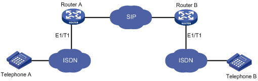
As shown in Figure 3, to transparently tunnel QSIG signaling from Router A to Router B over the SIP network, configure the signaling forward rawmsg command on Router A. When Router B receives a SIP message carrying QSIG signaling from Router A, it extracts the QSIG signaling from the SIP message and sends it to the ISDN side. When Router B receives QSIG signaling from the ISDN side, it sends the QSIG signaling in a SIP message to Router A.
Figure 3 Tunneling QSIG over SIP-T
Restrictions and guidelines
The SIP server might fail to interpret SIP messages carrying QSIG signaling. As a best practice, do not enable QSIG tunneling over SIP-T on a network where the device communicates with the SIP server.
Procedure
1. Enter system view.
system-view
2. Enter voice view.
voice-setup
3. Enter dial program view.
dial-program
4. Enter VoIP entity view.
entity entity-number voip
5. Enable QSIG tunneling over SIP-T.
signaling forward rawmsg
By default, QSIG tunneling over SIP-T is disabled.
If the ISDN network uses overlap sending, the device does not support QSIG tunneling over SIP-T.
Display and maintenance commands for SIP
Execute display commands in any view and reset commands in user view.
|
Task |
Command |
|
Display trusted node information. |
display voice ip address trusted list |
|
Display SIP UA registration status information. |
display voice sip register-status |
|
Display PSTN cause-to-SIP status mappings. |
display voice sip map { pstn-sip | sip-pstn } |
|
Display SIP calling information. |
display voice sip call |
|
Display information about SIP connections. |
display voice sip connection { tcp | tls } |
|
Disconnect a specific SIP connection. |
reset voice sip connection { tcp | tls } id conn-id |
SIP UA configuration examples
Example: Configuring direct SIP calling
Network configuration
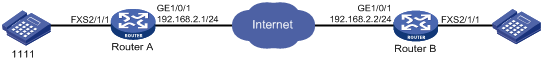
As shown in Figure 4, configure direct SIP calling on Router A and Router B so the phones 1111 and 2222 can call each other.
Procedure
1. Configure Router A:
# Assign an IP address to GigabitEthernet 1/0/1.
<RouterA> system-view
[RouterA] interface gigabitethernet 1/0/1
[RouterA-GigabitEthernet1/0/1] ip address 192.168.2.1 255.255.255.0
[RouterA-GigabitEthernet1/0/1] quit
# Set the call destination address to 192.168.2.2, and set the called number to 2222 on VoIP entity 2222.
[RouterA] voice-setup
[RouterA-voice] dial-program
[RouterA-voice-dial] entity 2222 voip
[RouterA-voice-dial-entity2222] address sip ip 192.168.2.2
[RouterA-voice-dial-entity2222] match-template 2222
[RouterA-voice-dial-entity2222] quit
# Bind FXS interface 2/1/1 to POTS entity 1111, and set the local number to 1111 on the POTS entity.
[RouterA-voice-dial] entity 1111 pots
[RouterA-voice-dial-entity1111] line 2/1/1
[RouterA-voice-dial-entity1111] match-template 1111
2. Configure Router B:
# Assign an IP address to GigabitEthernet 1/0/1.
<RouterB> system-view
[RouterB] interface gigabitethernet 1/0/1
[RouterB-GigabitEthernet1/0/1] ip address 192.168.2.2 255.255.255.0
[RouterB-GigabitEthernet1/0/1] quit
# Bind FXS interface 2/1/1 to POTS entity 2222, and set the local number to 2222 on the POTS entity.
[RouterB] voice-setup
[RouterB-voice] dial-program
[RouterB-voice-dial] entity 2222 pots
[RouterB-voice-dial-entity2222] line 2/1/1
[RouterB-voice-dial-entity2222] match-template 2222
[RouterB-voice-dial-entity2222] quit
# Set the call destination address to 192.168.2.1, and set the called number to 1111 on VoIP entity 1111.
[RouterB-voice-dial]entity 1111 voip
[RouterB-voice-dial-entity1111] address sip ip 192.168.2.1
[RouterB-voice-dial-entity1111] match-template 1111
Verifying the configuration
# Place calls to verify that phone 1111 and phone 2222 can call each other.
# Execute the display voice sip call command to display the SIP call information.
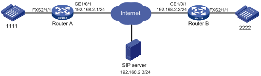
Example: Configuring SIP calling through a SIP server
Network configuration
As shown in Figure 5, configure SIP calling through the SIP server on Router A and Router B so the phones 1111 and 2222 can call each other.
On Router A, all phone numbers use the same username routerA and password 1234.
On Router B, phone number 2222 uses the username routerB, password 7890, and domain name server1.
Procedure
1. Configure Router A:
# Assign an IP address to GigabitEthernet 1/0/1.
<RouterA> system-view
[RouterA] interface gigabitethernet 1/0/1
[RouterA-GigabitEthernet1/0/1] ip address 192.168.2.1 255.255.255.0
[RouterA-GigabitEthernet1/0/1] quit
# Specify the SIP registrar and proxy server.
[RouterA] voice-setup
[RouterA-voice] sip
[RouterA-voice-sip] registrar 1 ip 192.168.2.3
[RouterA-voice-sip] proxy ip 192.168.2.3
# Configure global SIP credentials that include username routerA and plaintext password 1234.
[RouterA-voice-sip] user routerA password simple 1234
[RouterA-voice-sip] quit
# Bind FXS interface 2/1/1 to POTS entity 1111, and set the local number to 1111 on the POTS entity.
[RouterA-voice] dial-program
[RouterA-voice-dial] entity 1111 pots
[RouterA-voice-dial-entity1111] line 2/1/1
[RouterA-voice-dial-entity1111] match-template 1111
[RouterA-voice-dial-entity1111] quit
# Configure VoIP entity 2222 to get the call destination address from the proxy server, and set the called number to 2222 on the VoIP entity.
[RouterA-voice-dial] entity 2222 voip
[RouterA-voice-dial-entity2222] address sip proxy
[RouterA-voice-dial-entity2222] match-template 2222
[RouterA-voice-dial-entity2222] quit
2. Configure Router B:
# Assign an IP address to GigabitEthernet 1/0/1.
<RouterB> system-view
[RouterB] interface gigabitethernet 1/0/1
[RouterB-GigabitEthernet1/0/1] ip address 192.168.2.2 255.255.255.0
[RouterB-GigabitEthernet1/0/1] quit
# Specify the SIP registrar and proxy server.
[RouterB] voice-setup
[RouterB-voice] sip
[RouterB-voice-sip] registrar 1 ip 192.168.2.3
[RouterB-voice-sip] proxy ip 192.168.2.3
[RouterB-voice-sip] quit
# Bind FXS interface 2/1/1 to POTS entity 2222, and set the local number to 2222 on the POTS entity.
[RouterB-voice] dial-program
[RouterB-voice-dial] entity 2222 pots
[RouterB-voice-dial-entity2222] line 2/1/1
[RouterB-voice-dial-entity2222] match-template 2222
# Configure SIP credentials that include username routerB, plaintext password 7890, and domain name server1 for POTS entity 2222.
[RouterB-voice-dial-entity2222] user routerB password simple 7890 realm server1
# Configure VoIP entity 2222 to get the call destination address from the proxy server, and set the called number to 1111 on the VoIP entity.
[RouterB-voice-dial-entity2222] quit
[RouterB-voice-dial] entity 1111 voip
[RouterB-voice-dial-entity1111] address sip proxy
[RouterB-voice-dial-entity1111] match-template 1111
[RouterB-voice-dial-entity1111] quit
Verifying the configuration
# After the routers register phone numbers on the registrar, place calls to verify that phone 1111 and phone 2222 can call each other through the SIP proxy server. (Details not shown.)
# Execute the display voice sip register-status command to display the registration state for phones 1111 and 2222. (Details not shown.)
# Execute the display voice sip call command to display the SIP call information. (Details not shown.)
Example: Configuring SIP calling through DNS
Network configuration
As shown in Figure 6, configure Router A to get the call destination address through DNS, and configure Router B to use a static call destination address so the phones 1111 and 2222 can call each other.
Procedure
1. Configure Router A:
# Assign an IP address to GigabitEthernet 1/0/1.
<RouterA> system-view
[RouterA] interface gigabitethernet 1/0/1
[RouterA-GigabitEthernet1/0/1] ip address 192.168.2.1 255.255.255.0
[RouterA-GigabitEthernet1/0/1] quit
# Map the IP address 192.168.2.2 to the host name cc.news.com.
[RouterA] ip host cc.news.com 192.168.2.2
# Configure the VoIP entity 2222 to call the destination through domain name cc.news.com, and set the called number to 2222 on the VoIP entity.
[RouterA] voice-setup
[RouterA-voice] dial-program
[RouterA-voice-dial] entity 2222 voip
[RouterA-voice-dial-entity2222] address sip dns cc.news.com port 5060
[RouterA-voice-dial-entity2222] match-template 2222
[RouterA-voice-dial-entity2222] quit
# Bind FXS interface 2/1/1 to POTS entity 1111, and set the local number to 1111 on the POTS entity.
[RouterA-voice-dial] entity 1111 pots
[RouterA-voice-dial-entity1111] line 2/1/1
[RouterA-voice-dial-entity1111] match-template 1111
2. Configure Router B:
# Assign an IP address to GigabitEthernet 1/0/1.
<RouterB> system-view
[RouterB] interface gigabitethernet 1/0/1
[RouterB-GigabitEthernet1/0/1] ip address 192.168.2.2 255.255.255.0
[RouterB-GigabitEthernet1/0/1] quit
# Bind FXS interface 2/1/1 to POTS entity 2222, and set the local number to 2222 on the POTS entity.
<RouterB> system-view
[RouterB] voice-setup
[RouterB-voice] dial-program
[RouterB-voice-dial] entity 2222 pots
[RouterB-voice-dial-entity2222] line 2/1/1
[RouterB-voice-dial-entity2222] match-template 2222
[RouterB-voice-dial-entity2222] quit
# Set the destination address to 192.168.2.1, and set the called number to 1111 on VoIP entity 1111.
[RouterB-voice-dial]entity 1111 voip
[RouterB-voice-dial-entity1111] address sip ip 192.168.2.1
[RouterB-voice-dial-entity1111] match-template 1111
Verifying the configuration
# Place calls to verify that phone 1111 and phone 2222 can call each other. (Details not shown.)
# Execute the display voice sip call command to display the SIP call information. (Details not shown.)
Example: Configuring SIP to use TCP as the transport protocol
Network configuration
As shown in Figure 7, configure SIP to use TCP as the transport protocol on Router A and Router B, so phone 1111 can call phone 2222 over TCP.

Procedure
1. Configure Router A:
# Assign an IP address to GigabitEthernet 1/0/1.
<RouterA> system-view
[RouterA] interface gigabitethernet 1/0/1
[RouterA-GigabitEthernet1/0/1] ip address 192.168.2.1 255.255.255.0
[RouterA-GigabitEthernet1/0/1] quit
# Configure TCP as the global transport protocol for outgoing SIP calls.
[RouterA] voice-setup
[RouterA-voice] sip
[RouterA-voice-sip] session transport tcp
[RouterA-voice-sip] quit
# Set the destination IP address to 192.168.2.2, and set the called number to 2222 on VoIP entity 2222.
[RouterA-voice] dial-program
[RouterA-voice-dial] entity 2222 voip
[RouterA-voice-dial-entity2222] address sip ip 192.168.2.2
[RouterA-voice-dial-entity2222] match-template 2222
[RouterA-voice-dial-entity2222] quit
# Bind FXS interface line 2/1/1 to POTS entity 1111, and set the local number to 1111 on the POTS entity.
[RouterA-voice-dial] entity 1111 pots
[RouterA-voice-dial-entity1111] line 2/1/1
[RouterA-voice-dial-entity1111] match-template 1111
2. Configure Router B:
# Assign an IP address to GigabitEthernet 1/0/1.
<RouterB> system-view
[RouterB] interface gigabitethernet 1/0/1
[RouterB-GigabitEthernet1/0/1] ip address 192.168.2.2 255.255.255.0
[RouterB-GigabitEthernet1/0/1] quit
# Enable the TCP listening port. By default, the TCP listening port is enabled.
[RouterB] voice-setup
[RouterB-voice] sip
[RouterB-voice-sip] transport tcp
[RouterB-voice-sip] quit
# Bind FXS interface 2/1/1 to POTS entity 2222, and set the local number to 2222 on the POTS entity.
[RouterB-voice] dial-program
[RouterB-voice-dial] entity 2222 pots
[RouterB-voice-dial-entity2222] line 2/1/1
[RouterB-voice-dial-entity2222] match-template 2222
# Set the destination address to 192.168.2.1, and set the called number to 1111 on VoIP entity 1111.
[RouterB-voice-dial]entity 1111 voip
[RouterB-voice-dial-entity1111] address sip ip 192.168.2.1
[RouterB-voice-dial-entity1111] match-template 1111
Verifying the configuration
# Place a call to verify that phone 1111 can call phone 2222 over TCP. (Details not shown.)
# Execute the display voice sip connection tcp command to display TCP connection information. (Details not shown.)
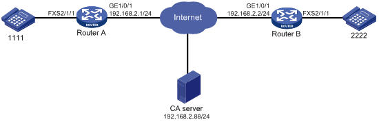
Example: Configuring SIP to use TLS as the transport protocol
Network configuration
As shown in Figure 8, configure SIP to use TLS as the transport protocol on Router A and Router B, so phone 1111 can call phone 2222 over TLS.
Procedure
In this example, the CA server runs RSA Keon.
To make sure the certificate on the device is valid, the device system time must be earlier than the expiration time of the certificate.
1. Configure Router A:
# Assign an IP address to GigabitEthernet 1/0/1.
<RouterA> system-view
[RouterA] interface gigabitethernet 1/0/1
[RouterA-GigabitEthernet1/0/1] ip address 192.168.2.1 255.255.255.0
[RouterA-GigabitEthernet1/0/1] quit
# Create a PKI entity named aaa with the common name as RouterA.
[RouterA] pki entity aaa
[RouterA-pki-entity-aaa] common-name RouterA
[RouterA-pki-entity-aaa] quit
# Create a PKI domain named voice, and specify the name of the trusted CA as voice.
[RouterA] pki domain voice
[RouterA-pki-domain-voice] ca identifier voice
# Configure the URL of the registration server in the form of http://host:port/Issuing Jurisdiction ID, where Issuing Jurisdiction ID is a hexadecimal string generated on the CA server.
[RouterA-pki-domain-voice] certificate request url http://192.168.2.88:446/bd0683e5a369eb4edbb4ef502eaca6ec42d24e97
# Specify the CA for accepting certificate requests.
[RouterA-pki-domain-voice] certificate request from ca
# Specify the PKI entity name as aaa, and specify the RSA key pair as keyname and the purpose as general.
[RouterA-pki-domain-voice] certificate request entity aaa
[RouterA-pki-domain-voice] public-key rsa general name keyname
[RouterA-pki-domain-voice] quit
# Generate a local RSA key pair named keyname.
[RouterA] public-key local create rsa name keyname
# Obtain the CA certificate and save it locally.
[RouterA] pki retrieve-certificate domain voice ca
# Submit a certificate request manually.
[RouterA] pki request-certificate domain voice
# Create an SSL server policy, and specify a PKI domain for the SSL server policy.
[RouterA] ssl server-policy server
[RouterA-ssl-server-policy-server] pki-domain voice
# Create an SSL client policy, and specify a PKI domain for the SSL client policy.
[RouterA] ssl client-policy client
[RouterA-ssl-client-policy-client] pki-domain voice
# Specify SSL policies to be used by TLS.
[RouterA] voice-setup
[RouterA-voice] sip
[RouterA-voice-sip] crypto ssl-server-policy server
[RouterA-voice-sip] crypto ssl-client-policy client
# Configure TLS as the global transport protocol for outgoing SIP calls.
[RouterA-voice-sip] session transport tcp tls
# Enable the TLS listening port.
[RouterA-voice-sip] transport tcp tls
[RouterA-voice-sip] quit
# Set the destination IP address and port number to 192.168.2.2 and 5061, and set the called number to 2222 on VoIP entity 2222.
[RouterA-voice] dial-program
[RouterA-voice-dial] entity 2222 voip
[RouterA-voice-dial-entity2222] address sip ip 192.168.2.2 port 5061
[RouterA-voice-dial-entity2222] match-template 2222
[RouterA-voice-dial-entity2222] quit
# Bind FXS interface 2/1/1 to POTS entity 1111, and set the local number to 1111 on the POTS entity.
[RouterA-voice-dial] entity 1111 pots
[RouterA-voice-dial-entity1111] line 2/1/1
[RouterA-voice-dial-entity1111] match-template 1111
2. Configure Router B:
# Assign an IP address to GigabitEthernet 1/0/1.
<RouterB> system-view
[RouterB] interface gigabitethernet 1/0/1
[RouterB-GigabitEthernet1/0/1] ip address 192.168.2.2 255.255.255.0
[RouterB-GigabitEthernet1/0/1] quit
# Create a PKI entity named aaa with the common name as RouterB.
[RouterB] pki entity aaa
[RouterB-pki-entity-aaa] common-name RouterB
[RouterB-pki-entity-aaa] quit
# Create a PKI domain named voice, and specify the name of the trusted CA as voice.
[RouterB] pki domain voice
[RouterB-pki-domain-voice] ca identifier voice
# Configure the URL of the registration server in the form of http://host:port/Issuing Jurisdiction ID, where Issuing Jurisdiction ID is a hexadecimal string generated on the CA server.
[RouterB-pki-domain-voice] certificate request url http://192.168.2.88:446/bd0683e5a369eb4edbb4ef502eaca6ec42d24e97
# Specify the CA for accepting certificate requests.
[RouterB-pki-domain-voice] certificate request from ca
# Specify the PKI entity name as voice.
[RouterB-pki-domain-voice] certificate request entity aaa
[RouterB-pki-domain-voice] quit
# Generate a local RSA key pair.
[RouterB] public-key local create rsa
# Obtain the CA certificate and save it locally.
[RouterB] pki retrieve-certificate domain voice ca
# Submit a certificate request manually.
[RouterB] pki request-certificate domain voice
# Create an SSL server policy, and specify a PKI domain for the SSL server policy.
[RouterB] ssl server-policy server
[RouterB-ssl-server-policy-server] pki-domain voice
# Create an SSL client policy, and specify a PKI domain for the SSL client policy.
[RouterB] ssl client-policy client
[RouterB-ssl-client-policy-client] pki-domain voice
# Specify SSL policies to be used by TLS.
[RouterB] voice-setup
[RouterB-voice] sip
[RouterB-voice-sip] crypto ssl-server-policy server
[RouterB-voice-sip] crypto ssl-client-policy client
# Specify TLS as the global transport protocol for outgoing SIP calls.
[RouterB-voice-sip] session transport tcp tls
# Enable the TLS listening port.
[RouterB-voice-sip] transport tcp tls
[RouterB-voice-sip] quit
# Bind FXS interface 2/1/1 to POTS entity 2222, and set the local number to 2222 on the POTS entity.
[RouterB-voice] dial-program
[RouterB-voice-dial] entity 2222 pots
[RouterB-voice-dial-entity2222] line 2/1/1
[RouterB-voice-dial-entity2222] match-template 2222
# Set the destination IP address and port number to 192.168.2.1 and 5061, and set the called number to 1111 on VoIP entity 1111.
[RouterB-voice-dial] entity 1111 voip
[RouterB-voice-dial-entity1111] address sip ip 192.168.2.1 port 5061
[RouterB-voice-dial-entity1111] match-template 1111
Verifying the configuration
# Place calls to verify that phone 1111 and phone 2222 can call each other over TLS. (Details not shown.)
# Execute the display voice sip connection tls command to display TLS connection information. (Details not shown.)
Example: Configuring out-of-band DTMF signaling
Network configuration
As shown in Figure 9, configure Router A and Router B to use out-of-band signaling to transmit DTMF tones so the phones 1111 and 2222 can call each other.
Procedure
1. Configure Router A:
# Assign an IP address to GigabitEthernet 1/0/1.
<RouterA> system-view
[RouterA] interface gigabitethernet 1/0/1
[RouterA-GigabitEthernet1/0/1] ip address 192.168.2.1 255.255.255.0
[RouterA-GigabitEthernet1/0/1] quit
# Set the call destination address to 192.168.2.2, and set the called number to 2222 on VoIP entity 2222.
[RouterA] voice-setup
[RouterA-voice] dial-program
[RouterA-voice-dial] entity 2222 voip
[RouterA-voice-dial-entity2222] address sip ip 192.168.2.2
[RouterA-voice-dial-entity2222] match-template 2222
# Enable out-of-band DTMF signaling for VoIP entity 2222.
[RouterA-voice-dial-entity2222] outband sip
[RouterA-voice-dial-entity2222] quit
# Bind FXS interface 2/1/1 to POTS entity 1111, and set the local number to 1111 on the POTS entity.
[RouterA-voice-dial] entity 1111 pots
[RouterA-voice-dial-entity1111] line 2/1/1
[RouterA-voice-dial-entity1111] match-template 1111
# Enable out-of-band DTMF signaling for POTS entity 1111.
[RouterA-voice-dial-entity1111] outband sip
2. Configure Router B:
# Assign an IP address to GigabitEthernet 1/0/1.
<RouterB> system-view
[RouterB] interface gigabitethernet 1/0/1
[RouterB-GigabitEthernet1/0/1] ip address 192.168.2.2 255.255.255.0
[RouterB-GigabitEthernet1/0/1] quit
# Set the call destination address to 192.168.2.1, and set the called number to 1111 on VoIP entity 1111.
[RouterB] voice-setup
[RouterB-voice] dial-program
[RouterB-voice-dial] entity 1111 voip
[RouterB-voice-dial-entity1111] address sip ip 192.168.2.1
[RouterB-voice-dial-entity1111] match-template 1111
# Enable out-of-band DTMF signaling for VoIP entity 1111.
[RouterB-voice-dial-entity1111] outband sip
[RouterB-voice-dial-entity1111] quit
# Bind FXS interface 2/1/1 to POTS entity 2222, and set the local number to 2222 on the POTS entity.
[RouterB-voice-dial] entity 2222 pots
[RouterB-voice-dial-entity2222] line 2/1/1
[RouterB-voice-dial-entity2222] match-template 2222
# Enable out-of-band DTMF signaling for POTS entity 2222.
[RouterB-voice-dial-entity2222] outband sip
Verify the configuration.
# Place calls to verity that phones 1111 and 2222 can call each other. (Details not shown.)
# Press keys on one phone during a call to verify that DTMF tones are transmitted out of band to the other phone. (Details not shown.)
Configuring SIP trunk
About SIP trunk
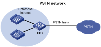
Background
As shown in Figure 10, in a typical telephone network, a PBX forwards internal calls among enterprise phones and forwards outbound calls over a PSTN trunk.
Figure 10 Typical telephone network
With the development of IP technology, many enterprises deploy SIP-based IP-PBX networks as shown in Figure 11. All internal calls are placed using SIP, and external calls are still placed over a PSTN trunk. The problem is that the enterprises have to maintain both the SIP network and PSTN trunk, which increases the difficulty of network management.
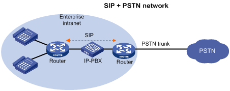
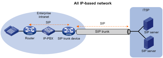
As more enterprise IP-PBX networks run SIP and more Internet Telephone Service Providers (ITSPs) use SIP to provide basic voice communication structures, enterprises urgently need a technology that can connect the enterprise IP-PBX network to the ITSP over SIP. This technology is called SIP trunk. A typical network diagram of SIP trunk is shown in Figure 12.
The SIP trunk feature can be embedded into the voice gateway or the firewall deployed at the edge of an enterprise private network. The device providing the SIP trunk feature is called the SIP trunk device, or the SIP trunk gateway.
Figure 12 All IP-based network
Features
SIP trunk has the following features:
· The SIP trunk device and the ITSP only establish one secure and QoS guaranteed SIP trunk link. The SIP trunk link can carry multiple concurrent calls, and the ITSP only authenticates the link instead of each SIP call carried on this link.
· The enterprise IP-PBX forwards internal calls. The SIP trunk device forwards outbound calls to the ITSP, and then the devices in the ITSP forward the calls to the PSTN. Enterprises do not need to maintain the PSTN trunk, which reduces the costs of hardware and maintenance.
· The enterprise can connect to multiple ITSP by setting destination addresses.
· With the SIP trunk device deployed, the entire network can use SIP to better support IP communication services, such as voice, video conferencing, and instant messaging.
· The SIP trunk device initiates a new call request to the ITSP on behalf of the user after receiving a call request from the user, and both the user and the ITSP communicate only with the SIP trunk device. The SIP trunk device forwards both SIP signaling messages and RTP media messages.
Typical applications
The SIP trunk device is deployed between the enterprise IP-PBX and the ITSP. All internal calls are placed by the enterprise IP-PBX. All outbound calls are forwarded by the SIP trunk device to the ITSP through the SIP trunk link. Figure 13 shows a typical SIP trunk technology.
Figure 13 SIP trunk network diagram
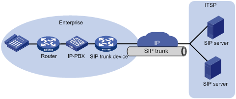
Protocols and standards
· RFC 3261
· RFC 3515
· SIP connect Technical Recommendation v1.1
Restrictions: Hardware compatibility with SIP trunk
|
Hardware |
SIP trunk compatibility |
|
MSR810, MSR810-W, MSR810-W-DB, MSR810-LM, MSR810-W-LM, MSR810-10-PoE, MSR810-LM-HK, MSR810-W-LM-HK, MSR810-LMS-EA |
MSR810, MSR810-W, MSR810-W-DB, MSR810-LM, MSR810-W-LM, MSR810-10-PoE, MSR810-LM-HK, MSR810-W-LM-HK: Yes MSR810-LMS-EA: No |
|
MSR810-LMS, MSR810-LUS |
No |
|
MSR2600-6-X1 |
No |
|
MSR2600-10-X1 |
Yes |
|
MSR 2630 |
Yes |
|
MSR3600-28, MSR3600-51 |
Yes |
|
MSR3600-28-SI, MSR3600-51-SI |
No |
|
MSR3600-28-X1, MSR3600-28-X1-DP, MSR3600-51-X1, MSR3600-51-X1-DP |
No |
|
MSR3610-I-DP, MSR3610-IE-DP |
No |
|
MSR3610-X1, MSR3610-X1-DP, MSR3610-X1-DC, MSR3610-X1-DP-DC |
Yes |
|
MSR 3610, MSR 3620, MSR 3620-DP, MSR 3640, MSR 3660 |
Yes |
|
MSR3610-G, MSR3620-G |
No |
Restrictions: Licensing requirements for SIP trunk
To support SIP trunk, some device models require the Voice Software License. For more information, see license management in Fundamentals Configuration Guide.
SIP trunk tasks at a glance
To configure SIP trunk, perform the following tasks:
1. Enabling SIP-to-SIP calling
2. Configuring a SIP trunk account
3. (Optional.) Enabling codec transparent transmission
4. (Optional.) Enabling media flow-around
5. (Optional.) Enabling DO-EO conversion
Prerequisites for SIP trunk
Configure VoIP entities on the devices next to the SIP trunk. Make sure the two devices can establish calls.
Enabling SIP-to-SIP calling
About enabling SIP-to-SIP calling
After you enable SIP-to-SIP calling, the device works as a SIP trunk device. As a best practice, do not use a SIP trunk device as a SIP UA.
Procedure
1. Enter system view.
system-view
2. Enter voice view.
voice-setup
3. Enable SIP-to-SIP calling.
allow-connections sip to sip
By default, SIP-to-SIP calling is disabled.
Configuring a SIP trunk account
About SIP trunk accounts
A SIP trunk account contains a phone number, credentials, and realms assigned by the service provider. SIP can send a REGISTER request for the phone number to up to six registrars specified by using the registrar command. SIP uses the realm value in 401/407 responses from the registrars to identify the matching credentials. You can configure up to 12 realm values for a phone number, and up to 128 SIP trunk accounts on the device.
Procedure
1. Enter system view.
system-view
2. Enter voice view.
voice-setup
3. Enter SIP view.
sip
4. Create an SIP trunk account.
credentials number number username username password { cipher | simple } string realm realm
By default, no SIP trunk accounts exist.
5. Specify a registrar.
registrar registrar-index { ip ip-address | dns domain-name } [ port port-number ] [ expires seconds ] [ refresh-ratio ratio-percentage ]
Enabling codec transparent transmission
About codec transparent transmission
If the SIP trunk device does not support any codecs on the calling and called parties, you can enable codec transparent transmission. The SIP trunk device transparently forwards codec capability sets between the two parties without intervening codec negotiation.
Procedure
1. Enter system view.
system-view
2. Enter voice view.
voice-setup
3. Enter dial program view.
dial-program
4. Enter VoIP entity view.
entity entity-number voip
5. Enable codec transparent transmission.
codec transparent
By default, codec transparent transmission is disabled.
Enabling media flow-around
About SIP media flow-around
This feature enables the SIP trunk device to directly forward media packets between SIP endpoints, without changing the media address for the media packets.
Procedure
1. Enter system view.
system-view
2. Enter voice view.
voice-setup
3. Enter dial program view.
dial-program
4. Enter VoIP entity view.
entity entity-number voip
5. Enable media flow-around.
media flow-around
By default, media flow-around is disabled. The SIP trunk device changes the media address of a media packet to its own address before forwarding the media packet.
Enabling DO-EO conversion
About DO-EO conversion
An INVITE request with SDP Offer is an early offer, and an INVITE request without SDP Offer is a delayed offer. Some ITSPs mandate early offer calls for charge security. To meet this requirement, enable delayed offer to early offer (DO-EO) conversion on the SIP trunk device.
Restrictions and guidelines
This configuration does not take effect if codec transparent transmission or media flow-around is enabled.
Procedure
1. Enter system view.
system-view
2. Enter voice view.
voice-setup
3. Enter dial program view.
dial-program
4. Enter VoIP entity view.
entity entity-number voip
5. Enable DO-EO conversion.
voice-class sip early-offer forced
By default, DO-EO conversion is disabled.
Display and maintenance commands for SIP trunk
Execute display commands in any view.
|
Task |
Command |
|
Display SIP trunk account registration status information. |
display voice sip register-status |
SIP trunk configuration examples
Example: Configuring SIP trunk
Network configuration
As shown in Figure 14, configure the SIP trunk device to forward calls between the private network and public network.
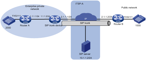
Procedure
1. Configure Router A:
# Set the local number to 2000 on POTS entity 2000.
<RouterA> system-view
[RouterA] voice-setup
[RouterA-voice] dial-program
[RouterA-voice-dial] entity 2000 pots
[RouterA-voice-dial-entity2000] line 2/1/1
[RouterA-voice-dial-entity2000] match-template 2000
[RouterA-voice-dial-entity2000] quit
# Set the called number to 1000, and the destination IP address to 1.1.1.2 (the address of the interface on the SIP trunk device) on VoIP entity 1000.
[RouterA-voice-dial] entity 1000 voip
[RouterA-voice-dial-entity1000] address sip ip 1.1.1.2
[RouterA-voice-dial-entity1000] match-template 1000
2. Configure the SIP trunk device:
# Enable SIP-to-SIP calling.
<TG> system-view
[TG] voice-setup
[TG-voice] allow-connections sip to sip
[TG-voice] sip
# Create a SIP trunk account for phone number 2000 that uses username 2000 and password 2000 in realm abc.
[TG-voice-sip] credentials number 2000 username 2000 password simple 2000 realm abc
# Specify the registrar 10.1.1.2 for the SIP trunk account.
[TG-voice-sip] registrar 1 ip 10.1.1.2
[TG-voice-sip] quit
# Set the destination address to 2.1.1.2 for outbound calls from private phone 2000 to public phone 1000.
[TG-voice] dial-program
[TG-voice-dial] entity 1 voip
[TG-voice-dial-entity1] address sip ip 2.1.1.2
[TG-voice-dial-entity1] match-template 1000
[TG-voice-dial-entity1] quit
# Set the destination address to 1.1.1.1 for inbound calls from public phone 1000 to private phone 2000.
[TG-voice-dial] entity 2 voip
[TG-voice-dial-entity2] address sip ip 1.1.1.1
[TG-voice-dial-entity2] match-template 2000
3. Configure Router B:
# Bind FXS interface 2/1/1 to POTS entity 1000, and set the local number to 1000 on the POTS entity.
<RouterB> system-view
[RouterB] voice-setup
[RouterB-voice] dial-program
[RouterB-voice-dial] entity 1000 pots
[RouterB-voice-dial-entity1000] line 2/1/1
[RouterB-voice-dial-entity1000] match-template 1000
[RouterB-voice-dial-entity1000] quit
# Set the called number to 2000, and the destination IP address to 2.1.1.1 (the address of the interface on the SIP trunk device) on VoIP entity 2000.
[RouterB-voice-dial] entity 2000 voip
[RouterB-voice-dial-entity2000] address sip ip 2.1.1.1
[RouterB-voice-dial-entity2000] match-template 2000
Verify the configuration:
# Display SIP trunk account information on the SIP trunk device.
[TG-voice-dial-entity2] display voice sip register-status
Number Entity Registrar Server Expires Status
--------------------------------------------------------------------------------
2000 0 10.1.1.2:5060 1802 Online
The output shows that the private phone number 2000 has registered with the server at 10.1.1.2.
# Execute the display voice sip call command to verify that all calls between the private network and public network pass through the SIP trunk device. (Details not shown.)
# On the SIP server of the ITSP, you can view only the interface address of the SIP trunk device, which means that the SIP trunk device can hide the information of private users. (Details not shown.)