- Table of Contents
- Related Documents
-
| Title | Size | Download |
|---|---|---|
| 01-Text | 460.17 KB |
Technical specifications and performance
AD162M56-1M1/AD162M56-1M1A power module
Front Panel of the power module
Installing the RPS1600-A in a 19-inch rack
Installing the RPS1600-A on a workbench
Connecting the grounding cable
Installing and removing the power module
Connecting the RPS1600-A to a PD
Product overview
Introduction
The RPS1600-A is an external power supply that uses AC inputs and provides eight lines of DC output, with a maximum output power of 3200 W (220 VAC input voltage) and 1600 W (110 VAC input voltage). It can provide DC power supply simultaneously for multiple powered devices (PDs), such as switches and routers. The RPS1600-A can serve as:
· A heavy-duty external PoE power supply
· A redundant power supply for PDs
Serving as a redundant power supply, the RPS1600-A offers the following functions:
· If using the same AC power source with a PD, when the internal power supply system of the PD fails, the RPS1600-A can provide DC power supply to the PD, ensuring uninterrupted operation of the PD.
· If using a different AC power source from the PD, when the AC power source to the PD fails, the RPS1600-A can provide DC power supply to the PD, ensuring uninterrupted operation of the PD.
The RPS1600-A adopts a power supply failover mechanism: when the power supply of the PD works properly, both the RPS1600-A and the PD’s power supply can supply power to implement load sharing; when the power supply of the PD fails, only the RPS1600-A works to ensure uninterrupted operation of the PD.
|
|
NOTE: As optional parts for the RPS1600-A, different types DC output cables are available depending on the requirement of the powered device. For details about the DC output cables, please consult H3C marketing or customer service staff. |
Front panel
The RPS1600-A has two power module slots, allowing two power modules to work in parallel, one of which is provided by default and the other is optional. For more information about the power modules, see “AD162M56-1M1/AD162M56-1M1A power module.”
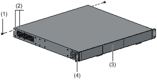
Figure 1 Front panel of the RPS1600-A

|
(1) Power module 1 (default) |
(2) Power module 2 (optional) |
Rear panel
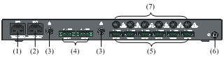
Figure 2 Rear panel of the RPS1600-A
|
(1) AC input for power module 1 |
(2) AC input for power module 2 |
|
(3) 25-A output reset buttons |
(4) 25-A DC outputs |
|
(5) 8-A DC outputs |
(6) Grounding screw |
|
(7) Fuses for the 8-A DC outputs |
|
|
|
NOTE: · Each of the two AC inputs is for one power module. · One reset button is provided for each of the two 25-A outputs. The left reset button controls the left 25-A output, while the right reset button controls the right 25-A output. For how to use the reset buttons, see Table 2. · One replaceable fuse is provided for each 8-A output. For how to use and replace the fuses, see Table 2 and “Replacing a fuse.” |
Technical specifications and performance
Table 1 Technical specifications of the RPS1600-A
|
Item |
Specifications |
|
Dimensions (H × W × D) |
44.2 × 440 × 397 mm (1.74 × 17.32 × 15.63 in) |
|
Weight |
< 8 kg (< 17.64 lb) |
|
Power module slots |
2 |
|
AC inputs |
100 VAC to 240 VAC, 47 Hz to 63 Hz |
|
DC outputs |
· 2 DC outputs: –55 V/ 25 A · 6 DC outputs: –55 V/8 A |
|
Max output power |
· With one power module: 1600 W · With two power modules: 3200 W For more information, see “Output power distribution.” |
|
Operating temperature |
–10°C to +50°C (14°F to 122°F) |
|
Relative humidity (noncondensing) |
5% to 95% |
|
|
NOTE: The design of this product complies with environmental protection requirements. Be sure to observe the relevant local laws and regulations when storing, using, or disposing of this product. |
The RPS1600-A supports a variety of protection features, as shown in Table 2.
Table 2 Protection features of the RPS1600-A
|
Item |
Description |
|
Input over-voltage protection |
When the input voltage exceeds 295 ± 5 VAC, the unit executes an over-voltage protection shutdown and displays an alarm through the alarm LED. When the input voltage comes down to 275 ± 5 VAC, the unit automatically recovers and clears the alarm. |
|
Input under-voltage protection |
When the input voltage comes down to 75 ± 5 VAC, the unit executes an under-voltage protection shutdown and displays an alarm through the alarm LED. When the input voltage rises to 85 ± 5 VAC, the unit automatically recovers and clears the alarm. |
|
Output over-voltage protection |
When the output voltage exceeds –59.5 VDC, the power module executes an over-voltage protection shutdown and displays an alarm through the alarm LED. To remove the fault, pull out the power module and insert it again, or turn off the AC input and turn it on again. |
|
Output over-current protection |
When the output current of a power module exceeds 31.5 ± 1.5 A, the power module executes an over-current protection shutdown and displays an alarm through the alarm LED. When the over-current condition is eliminated, the power module automatically recovers and clears the alarm. |
|
Per-output over-current protection and short-circuit protection |
A protection action of one output does not affect any other. · For a 25-A output, press the reset button to clear the condition; · For an 8-A output, check the corresponding fuse, and replace the fuse if it was blown to clear the condition. |
|
Over-temperature protection |
At temperatures between 65°C (149°F) and 75°C (167°F), the unit operates with reduced output power. At temperatures higher than 75°C (167°F), the unit executes an over-temperature protection shutdown and displays an alarm through the alarm LED. When the temperature comes down to 65°C (149°F), the unit automatically recovers and clears the alarm. |
AD162M56-1M1/AD162M56-1M1A power module
The power module is a hot-swappable internal AC-DC power supply for standalone use or for working in parallel. When working in parallel, the power modules automatically share the current in the power supply system. Each AD162M56-1M1/AD162M56-1M1A power module delivers a maximum output power of 1600 W.
Front Panel of the power module
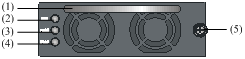
Figure 3 Front panel of the power module
|
(1) Handle |
(2) Run LED |
(3) Alarm LED |
|
(4) Fault LED |
(5) Captive screw |
|
LEDs description
Table 3 LEDs description
|
LED |
Color |
Status |
Fault description |
|
Run LED |
Green |
Normal: On Abnormal: Off |
· An AC mains problem has occurred. · The power module operates abnormally or has an alarm. |
|
Alarm LED |
Yellow |
Normal: Off Abnormal: On |
The power module is in an over-temperature, over-current, input over-voltage or under-voltage condition. |
|
Fault LED |
Red |
Normal: Off Abnormal: On |
The power module is shut down for output over-voltage or short-circuit protection, or has a fan fault or some other faults. |
|
|
CAUTION: · When the run LED is off, check whether an AC power input failure occurs. · When the alarm LED is on, check whether an input over-voltage or under-voltage, an output over-current, or an over-temperature condition occurs. · When the fault LED is on, check whether an output over-voltage or short-circuit condition or a fan fault occurs. |
Output power distribution
Table 4 Output power distribution
|
Number of power modules |
Input voltage |
Max output power per 8-A output |
Max output power per 25-A output |
Total max output power of 8 outputs |
|
1 |
220 VAC |
448 W |
1400 W |
1600 W |
|
110 VAC |
448 W |
800 W |
800 W |
|
|
2 |
220 VAC |
448 W |
1400 W |
3200 W |
|
110 VAC |
448 W |
1400 W |
1600 W |
|
|
WARNING! The RPS1600-A can provide power supply to multiple PDs simultaneously. Use one or two power modules depending on the power consumption of the PDs. Make sure that: · The system power consumption of each PD does not exceed the maximum output power of the corresponding DC output; · The total power consumption contributed by all the PDs does not exceed the total maximum output power of the RPS1600-A. |
Installation
Precautions
To avoid any device impairment and bodily injury caused by improper use, observe these rules:
· Do not place the RPS1600-A on an unstable case or table, and ensure that the cabinet and the workbench are firm enough to support the RPS1600-A and its accessories.
· Make sure that the cabinet and workbench has a good ventilation system, and enough room is left around the air intake and outlet of the RPS1600-A for heat dissipation. Never block the air intake and outlet of the RPS1600-A. (The air intake of the RPS1600-A is located on the front panel of the AD162M56-1M1/ AD162M56-1M1A. Air flows in through the air intake and flows out through the heat dissipation holes located at the two sides of the RPS1600-A.)
· Keep the RPS1600-A away from high-power radio transmitters, radars, and high-frequency devices working in high current. Use electromagnetic shielding when necessary.
· Make sure that the operating voltage of the power source matches the voltage required by the RPS1600-A.
· Interface cables must be routed indoors. Otherwise, over-voltage and over-current may damage the device. As for power cables from the outside of the building, you can add a dedicated lightning arrester at the input end of the cables.
· To enhance lightning protection, add a power lightning arrester at the input end.
· Wear an ESD-preventive wrist strap when installing the RPS1600-A, and make sure that the wrist strap has good skin contact.
· To avoid electric shock, never open the chassis of the RPS1600-A while it is in operation; try not to open the RPS1600-A even if it is not electrified.
· Unplug the power cable before cleaning the RPS1600-A.
· Keep the equipment room clean. The limits on the concentrations of dust and harmful gases in the equipment room are shown in Table 5 and Table 6.
Table 5 Limit on dust concentration
|
Mechanical active material |
Limit (particles/m3) |
|
Dust particles |
≤ 3 x 10⁴ (No visible dust on desk in three days) |
|
Note: Dust particle diameter ≥ 5 μm |
|
Table 6 Limits on harmful gas concentration
|
Gas |
Limit (mg/m3) |
|
SO2 |
0.2 |
|
H2S |
0.006 |
|
NH3 |
0.05 |
|
Cl2 |
0.01 |
Installing the RPS1600-A
The RPS1600-A can be installed either in a 19-inch standard rack or on a workbench.
Installing the RPS1600-A in a 19-inch rack
|
|
WARNING! Disconnect the AC power before installation. For security, unplug the power modules first, install the cabinet to the rack, and then insert the power modules. |
Mounting brackets
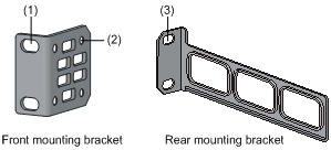
Figure 4 Front and rear mounting brackets
|
(1) Screw hole for fixing the front mounting bracket onto the cabinet (M6 screws required, not provided by default) |
|
(2) Screw hole for fixing the front mounting bracket to the RPS (the screws are provided) |
|
(3) Screw hole for fixing the rear mounting bracket onto the cabinet (M6 screws required, not provided by default) |
Install the RPS1600-A by using front and rear mounting brackets
Follow these steps to install the RPS1600-A by using front and rear mounting brackets:
1. Wear an ESD-preventive wrist strap (make sure it makes good skin contact and is well grounded), and check the grounding and stableness of the rack.
2. Unpack the supplied front mounting brackets and screws, and attach the front mounting brackets to the RPS1600-A with the screws. Figure 5 shows how to install a mounting bracket to one side of the switch. Install the other mounting bracket in the same way.
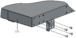
Figure 5 Install a front mounting bracket to the RPS1600-A
|
(1) Front panel of the RPS1600-A |
Figure 6 Attach weight-bearing screws
|
(1) Weight-bearing screws |
|
|
(2) Holes for mounting the weight-bearing screws (select one as needed) |
|
|
(3) Front panel of the RPS1600-A |
(4) Front mounting bracket |
4. In accordance with the RPS unit installation position in the rack, fix the rear mounting brackets to the rear square-holed posts by using M6 screws and cage nuts (user supplied), as shown in Figure 7.
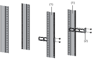
Figure 7 Install the rear mounting brackets to the rack
|
(1) Rear square-holed posts of the rack |
|
(2) Rear mounting bracket |
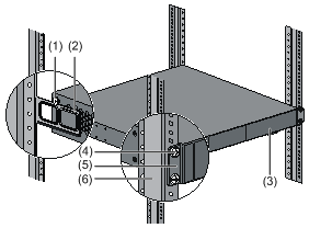
5. With one hand supporting the bottom and the other hand holding the front end of the RPS1600-A, gently push the RPS1600-A into the rack. After pushing the RPS1600-A into the rack, make sure of the close contact between the upper edges of the rear mounting brackets on the rack and the weight-bearing screws on the RPS1600-A, as shown in Figure 8.
6. Fix the front mounting brackets to the front square-holed posts of the rack by using M6 screws and cage nuts (user supplied). Make sure that the RPS1600-A is securely fixed with the front and rear mounting brackets on the rack, as shown in Figure 8.
Figure 8 Install the RPS1600-A to the rack by using front and rear mounting brackets
|
(1) Weight-bearing screw |
(2) Rear mounting bracket |
|
(3) Front panel of the RPS1600-A |
(4) M6 screw |
|
(5) Front mounting bracket |
(6) Front post of the rack |
|
|
NOTE: You can also install the front mounting brackets to the rear panel of the RPS1600-A. Then the rear panel of RPS1600-A will be attached to the front posts of the rack. The installation procedure is similar. |
Install the RPS1600-A by using the front mounting brackets and a rack shelf
1. Wear an ESD-preventive wrist strap and check the grounding and stableness of the rack.
2. Fix the rack shelf supplied with the rack horizontally at the appropriate position of the rack.
3. Unpack the supplied front mounting brackets and screws, and attach the front mounting brackets to the front end of the RPS1600-A with the screws, as shown in Figure 5.
4. Place the RPS1600-A horizontally on the rack shelf, gently push the unit into the rack along the rack shelf, and fix the mounting brackets to the front square-holed posts of the rack with M6 screws and cage nuts (user supplied).
Installing the RPS1600-A on a workbench
If a 19-inch standard rack is not available, you can place the RPS1600-A on a clean, stable workbench. Follow these steps to install the RPS1600-A on the workbench:
1. Cautiously turn the RPS1600-A upside down. Then, use a piece of dry, soft cloth to remove any oil stain or dust from the dents on the bottom of the chassis.
2. Peel off the stickers on the supplied foot pads and paste the foot pads into the dents on the chassis bottom.
Connecting the grounding cable
|
|
WARNING! Correctly connecting the grounding cable is crucial to lightning protection and EMI protection. |
Follow these steps to attach the OT terminal of the grounding cable to the grounding hole of the RPS unit:
1. Remove the grounding screw from the rear panel of the RPS unit.
2. Attach the grounding screw to the OT terminal of the grounding cable.
3. Use a screwdriver to fasten the grounding screw into the grounding screw hole.
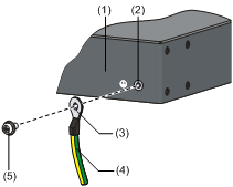
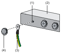
Figure 9 Connect the grounding cable to the grounding hole of the RPS unit
|
(1) Rear panel of the RPS unit |
(2) Grounding hole |
|
(3) OT terminal |
(4) Grounding cable |
|
(5) Grounding screw |
|
4. Connect the other OT terminal of the grounding cable to the grounding pole of the grounding strip, and fasten it with a hex nut.
Figure 10 Connect the grounding cable to the grounding strip
|
(1) Grounding pole |
(2) Grounding strip |
|
(3) Grounding cable |
(4) Hex nut |
Installing and removing the power module
Handle of the power module
The AD162M56-1M1/AD162M56-1M1A provides a handle, as shown in Figure 3. You can hold the handle to pull the module out from the chassis.
Installing the power module
Table 7 Install the power module
|
Procedure |
Description |
|
Install a power module |
Hold the handle of the power module and place the module to the installation position of the chassis, and then push the module until the rear end of the module touches the chassis. |
|
Lock the module |
Fix the captive screws on the panel to secure the power module to the chassis. |
Removing the power module
Table 8 Remove the power module
|
Procedure |
Description |
|
Release the screws |
Release the captive screws on the panel. |
|
Release the module |
Pull the handle to detach the module from the connector. |
|
Pull out the module |
Hold the handle to pull the module out. (Do not touch the module’s surface because it might be quite hot.) |
|
|
WARNING! The power module is hot swappable. However, before plugging out a module, make sure that the load will not exceed the total 8-line output power when one module is installed. |
Connecting the RPS1600-A to a PD
Connecting the cables
Follow these steps to connect the RPS1600-A to a PD:
1. Check that the power source to the RPS1600-A is disconnected and the PD is powered off.
2. Check that the chassis of the RPS1600-A and PD are properly grounded.
3. Plug one end of the DC output power cable into the DC input socket of the PD and the other end into the DC output socket of the RPS1600-A. Make sure the correct DC output interface and output cable are selected.
4. Connect the power source to the RPS1600-A and power on the PD.
|
|
WARNING! · No DC output cable is supplied with the RPS1600-A. You need to purchase one based on the PD model. · Check that the AC input and DC output cables are firmly connected to eliminate poor or loose contact. |
Commissioning the RPS1600-A
· Before powering on the RPS1600-A, check the AC input with a multimeter set to Ohms to eliminate any short circuit.
· Upon powering on the RPS1600-A, if the run LED is on, and the alarm LED and fault LED is off, the output is normal; if the alarm LED or fault LED on the front panel is on, the RPS1600-A works abnormally; if none of the run LED, alarm LED, and fault LED is on, an AC mains problem has occurred.
For more information about the LED description, see “LEDs description.”
Replacing a fuse
Follow these steps to replace a blown fuse:
1. Check that the RPS1600-A is powered off.
2. Turn the fuse cover anticlockwise to remove the fuse cover.
3. Remove the blown fuse and insert a spare fuse into the fuse cover. Verify that the fuse is in good contact with the bottom of the fuse cover.
4. Insert the new fuse together with the fuse cover into the fuse receptacle on the chassis, and turn the fuse cover clockwise to lock it in place.
|
|
WARNING! To prevent fire hazards, use fuses—with a rating of 10 A/250 V—provided with the RPS1600-A. |
