- Table of Contents
- Related Documents
-
| Title | Size | Download |
|---|---|---|
| 01-Text | 6.75 MB |
Contents
Space and cabling considerations
Attaching MPU air filter to the top hood
Installing the top hood and bottom plate
Installing the left and right doors
Installing the door kit for an S12508XC-AF/S12508M-AF switch
Attaching forehead air filters to the top hood
Installing the bottom plate, vertical slot air filters, and top hood
Installing the left and right doors
Installing the door kit for an S12504X-AF/S12504F-AF switch
Removing and cleaning the doors
Chassis air filter door kit views
Preparing for installation
You can install an H3C chassis front air filter door kit for the following devices:
· S12516X-AF/S12516F-AF switch.
· S12512X-AF/S12512F-AF switch.
· S12508X-AF/S12508F-AF switch.
· S12508XC-AF/S12508M-AF switch.
· S12504X-AF/S12504F-AF switch.
· CR19000-16 router.
· CR16016-X router.
· CR16008-X router.
Space and cabling considerations
To install an air filter door kit for a device installed or to be installed in a cabinet, make sure the cabinet meets the following requirements:
· The cabinet has a minimum inner width of 510 mm (20.08 in) so that the doors can be fully opened.
· A minimum distance of 150 mm (5.91 in) exists between the cabinet front posts and the cabinet door.
A maximum of 100 mm (3.94 in) cabling space is available if you install an air filter door kit for a device. To use copper or twisted pair cables (which are thick) to connect the ports on the device, make sure routing these cables does not interfere with the installation or use of the door kit.
Installation tools
The following installation tools are not provided with the door kit. Prepare them yourself.
· Phillips screwdriver.
· Flat-blade screwdriver.
· ESD wrist strap.
To facilitate the door kit installation, prepare screwdrivers with the shaft length greater than 150 mm (5.91 in).
Installing the door kit
Installing the door kit for an S12516X-AF/S12516F-AF, S12512X-AF/S12512F-AF, S12508X-AF/S12508F-AF, CR19000-16, CR16016-X, or CR16008-X device
|
|
IMPORTANT: As a best practice, complete the installation of cards before installing the door kit. |
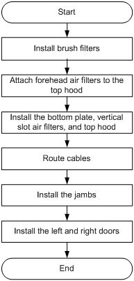
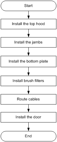
Installation flowchart
Figure 1 Installation flowchart
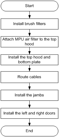
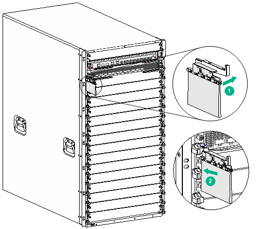
Installing brush filters
Brush filters are attached to the chassis through cable management brackets.
To install brush filters:
1. Attach brush filters to the cable management brackets, as shown by callout 1 in Figure 2.
Make sure space exists between the clamp of a brush filter and its attached cable management bracket so that slight moves between the two are allowed.
You do not need to attach brush filters to the bottom cable management brackets.
2. Attach the cable management bracket with the right brush filter to the right side of the chassis and the cable management with the left brush filter to the left side.
The right brush filter has an "R" mark. The left brush filter has an "L" mark.
3. To avoid interfering with the subsequent installations, comb the brush filters outwards.
Figure 2 Installing a brush filter
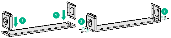
Attaching MPU air filter to the top hood
Before installing the top hood on the device, attach the MPU air filters to the top hood.
To attach MPU air filters to the top hood:
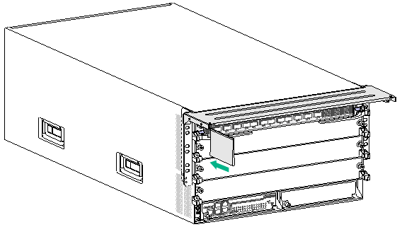
1. Place the top hood on a flat surface upside down.
2. Fit the bottom of each side pate into the grooves on the top hood, as shown by callout 1 in Figure 3.
3. Use two M3 countersunk-head screws to secure each MPU air filter to the top hood, as shown by callout 2 in Figure 3.
Figure 3 Attaching MPU air filters to the top hood
Installing the top hood and bottom plate
Installing the top hood
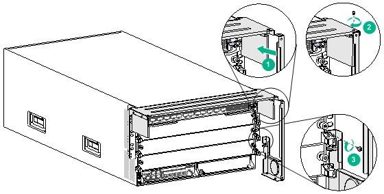
1. Align the three installation holes in the top hood with the installation holes in the chassis.
2. Insert an M3 pan-head screw through an installation hole in the top hood into the installation hole in the chassis. Turn the screw part way into the installation holes. See callout 1 in Figure 4.
3. Perform the same procedure to insert M3 pan-head screws into the other two installation holes, as shown by callouts 2 and 3 in Figure 4.
4. Fasten all the screws.
5. Slide a brush filter onto each air filter along the groove, as shown by callout 4 in Figure 4.
Figure 4 Installing the top hood
Installing the bottom plate
1. Align the four installation holes in the bottom plate with the installation holes in the chassis.
2. Insert an M3 pan-head screw through an installation hole in the bottom plate into the installation hole in the chassis. Turn the screw part way into the installation holes.
3. Perform the same procedure to insert M3 pan-head screws into the other three installation holes.
4. Fasten all the screws.
Figure 5 Installing the bottom plate
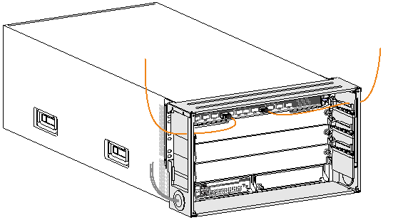
Cabling
Route the card cables before installing the door jambs.
· Route the MPU cables through the round holes in the MPU air filters.
· Route the service module cables through the brush filters at the two sides of the service module slots.
Re-comb the brush filters after completing cabling to ensure dust prevention.
Figure 6 Routing cables
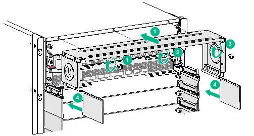
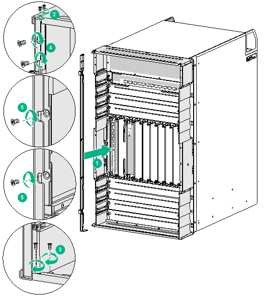
Installing the jambs
The left and right jambs are different in structure. The right jamb has an "R" mark. The left jamb has an "L" mark. Identify the left and right jambs before installation.
To install the jambs:
1. Fit the top and bottom of a jamb into the grooves on the top hood and bottom plate, respectively, as shown by callout 1 in Figure 7.
2. Use M3 countersunk-head screws to secure the jamb, Fasten screws on the top hood and bottom plate first and then on the MPU slot air filters, with two screws on each plate. See callouts 2 to 4 in Figure 7.
3. Perform the same steps to install the other jamb.
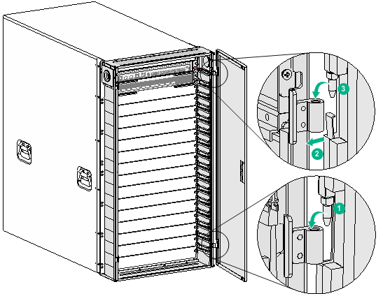
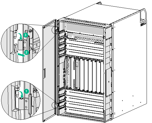
Installing the left and right doors
1. Place the right door vertical to the front panel of the device and close to a jamb.
2. Tilt the door slightly to ensure that the lower hinge pin on the door aligns with the hinge hole on the jamb. Insert the pin 3 mm (0.12 in) into the hole. See callout 1 in Figure 8.
3. Use the upper hinge on the jamb to press down the spring tab on the door and insert the upper hinge pin on the door into the hinge hole on the jamb. See callouts 2 and 3 in Figure 8.
4. Move the door slightly down to insert the two pins completely into the hinge holes.
5. Perform the same steps to install the left door.
Installing the door kit for an S12508XC-AF/S12508M-AF switch
|
|
IMPORTANT: As a best practice, complete the installation of cards before installing the door kit. |
Installation flowchart
Figure 9 Installation flowchart
Installing brush filters
Brush filters are attached to the chassis through cable management brackets.
To install brush filters:
1. Attach brush filters to cable management brackets, as shown by callout 1 in Figure 10.
Make sure space exists between the clamp of a brush filter and its attached cable management bracket so that slight moves between the two are allowed.
You do not need to attach brush filters to the bottom cable management brackets.
2. Attach the cable management bracket with the right brush filter to the right side of the chassis and the cable management with the left brush filter to the left side.
The right brush filter has an "R" mark. The left brush filter has an "L" mark.
3. To avoid interfering with the subsequent installations, comb the brush filters outwards.
Figure 10 Installing a brush filter
Attaching forehead air filters to the top hood
Before installing the top hood on the device, attach the forehead air filters to the top hood.
To attach forehead air filters to the top hood:
1. Place the top hood on a flat surface upside down.
2. Fit the bottom of each air filter into the grooves on the top hood, as shown by callout 1 in Figure 11.
3. Use two M3 countersunk-head screws to secure each air filter to the top hood, as shown by callout 2 in Figure 11.
Figure 11 Attaching forehead air filters to the top hood
Installing the bottom plate, vertical slot air filters, and top hood
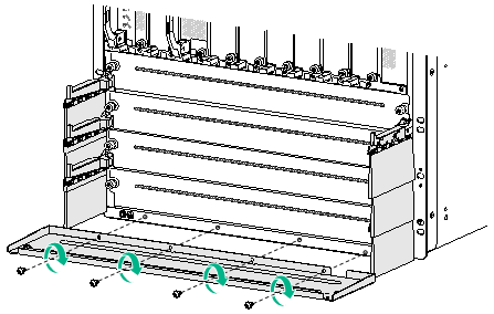
Installing the bottom plate
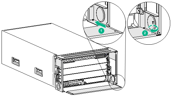
1. Align the four installation holes in the bottom plate with the installation holes in the chassis.
2. Insert an M3 pan-head screw through an installation hole in the bottom plate into the installation hole in the chassis. Turn the screw part way into the installation holes.
3. Perform the same procedure to insert M3 pan-head screws into the other three installation holes.
4. Fasten all the screws.
Figure 12 Installing the bottom plate
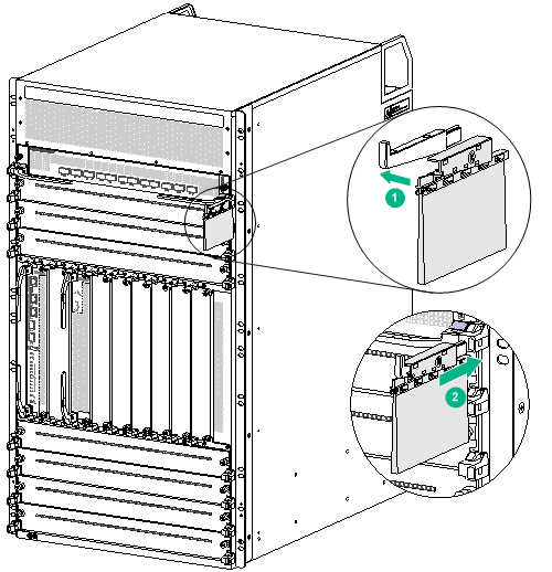
Installing vertical slot air filters
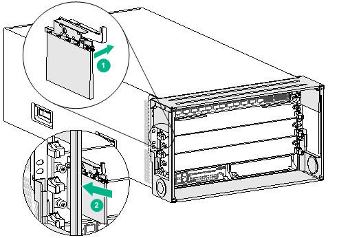
1. Press an air filter against a mounting bracket and align the captive screws on the air filter with the installation holes in the mounting bracket. Fasten the screws. See callouts 1 and 2 in Figure 13.
2. Slide the brush filter onto the air filter along the groove. See callout 3 in Figure 13.
3. Perform the same steps to install the other air filter.
Figure 13 Installing a vertical slot air filter
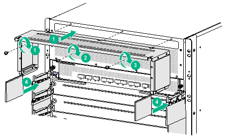
Installing the top hood
1. Align the three installation holes in the top hood with the installation holes in the chassis.
2. Insert an M3 pan-head screw through an installation hole in the top hood into the installation hole in the chassis. Turn the screw part way into the installation holes.
3. Perform the same procedure to insert M3 pan-head screws into the other two installation holes.
4. Fasten all the screws.
5. Slide a brush filter onto each forehead air filter along the groove, as shown by callout 4 in Figure 14.
Figure 14 Installing the top hood
Cabling
Route the card cables before installing jambs.
· Route the MPU cables through the brush filters above the vertical slot air filters.
· Route the service module cables through the brush filters at the two sides of the service module slots.
Re-comb the brush filters after completing cabling to ensure dust prevention.
Figure 15 Routing cables
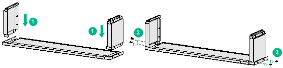
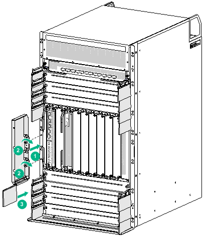
Installing the jambs
The left and right jambs are different in structure. The right jamb has an "R" mark. The left jamb has an "L" mark. Identify the left and right jambs before installation.
To install a jamb:
1. Fit the top and bottom of a jamb into the grooves on the top hood and bottom plate, respectively, as shown by callout 1 in Figure 16.
2. Use M3 countersunk-head screws to secure the jamb. Fasten screws on the top hood and bottom plate first and then on the forehead air filter and vertical slot air filter, with two screws on each plate. See callouts 2 to 5 in Figure 16.
3. Perform the same steps to install the other jamb.
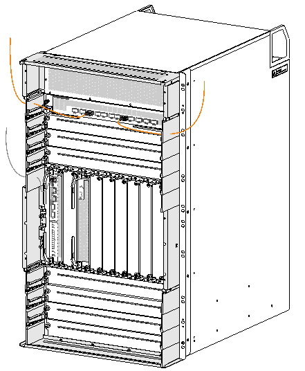
Installing the left and right doors
1. Place the left door vertical to the front panel of the device and close to a jamb.
2. Tilt the door slightly to ensure that the lower hinge pin on the door aligns with the hinge hole on the jamb. Insert the pin 3 mm (0.12 in) into the hole. See callout 1 in Figure 17.
3. Use the upper hinge on the jamb to press down the spring tab on the door and insert the upper hinge pin on the door into the hinge hole on the jamb. See callouts 2 and 3 in Figure 17.
4. Move the door slightly down to insert the two pins completely into the hinge holes.
5. Perform the same steps to install the right door.
Installing the door kit for an S12504X-AF/S12504F-AF switch
|
|
IMPORTANT: As a best practice, complete the installation of cards before installing the door kit. |
Installation flowchart
Figure 18 Installation flowchart
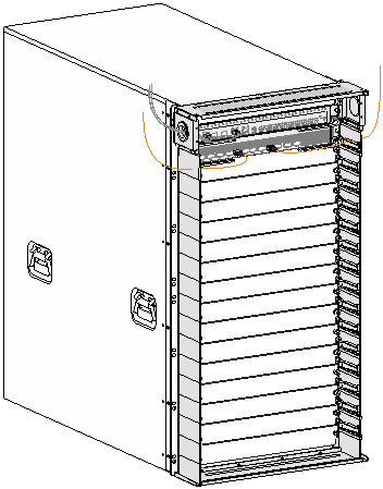
Installing the top hood
1. Align the installation holes in the top hood with the installation holes in the mounting brackets.
2. Insert an M3 pan-head screw through an installation hole in the top hood into the installation hole in the chassis. Turn the screw part way into the chassis.
3. Perform the same procedure to insert an M3 pan-head screw into the other installation hole.
4. Slide a brush filter onto each side of the top hood along the grooves. See Figure 20.
Figure 19 Installing the top hood
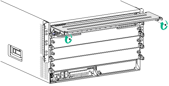
Figure 20 Attaching a brush filter to the top hood
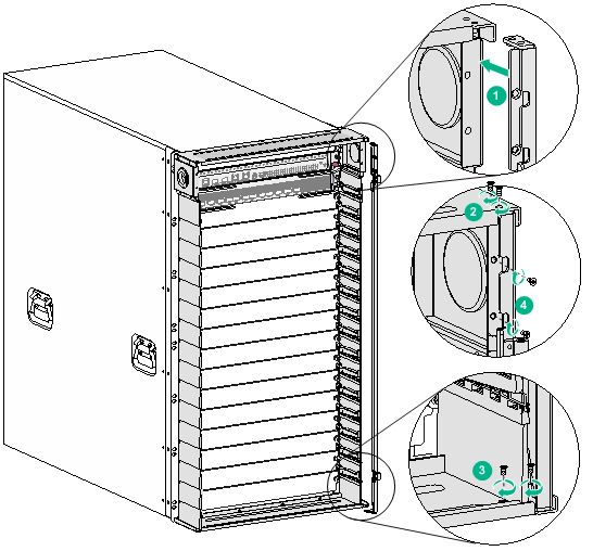
Installing the jambs
The left and right jambs are different in structure. Identify the left and right jambs before installation.
To install jambs:
1. Fit the top of a jamb into the groove on the top hood and make sure the guide pin on the jamb is inserted into a hole in the mounting bracket. Insert a countersunk-head screw into the screw hole on the top hood and fasten the screw, as shown by callout 2 in Figure 21.
2. Adjust the jamb to align the hole in the jamb with the installation hole in the mounting bracket. Insert an M3 pan-head screw part way into the holes. See callout 3 in Figure 21.
3. Perform the same steps to install the other jamb.
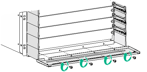
Installing the bottom plate
1. Slide the bottom plate onto the jamb bottom rails. Press down the bottom plate so that the mushroom screws on the jamb bottom rails secure the bottom plate in place. See callout 1 in Figure 22.
2. Adjust the jambs and the bottom plate. Insert an M3 countersunk-head screw into the installation hole at each side of the bottom plate and fasten the screw, as shown by callout 2 in Figure 22.
3. Fasten the pan-head screws that attach the top hood to the chassis and the jambs to the mounting brackets.
Figure 22 Installing the bottom plate
Installing brush filters
Brush filters are attached to the chassis through cable management brackets.
To install brush filters:
1. Attach brush filters to cable management brackets, as shown by callout 1 in Figure 23.
Make sure space exists between the clamp of a brush filter and its attached cable management bracket so that slight moves between the two are allowed.
You do not need to attach a brush filter to the bottom cable management brackets.
2. Attach the cable management bracket with the right brush filter to the right side of the chassis and the cable management bracket with the left brush filter to the left side.
The right brush filter has an "R" mark. The left brush filter has an "L" mark.
3. To avoid interfering with the subsequent installations, comb the brush filters outwards.
Figure 23 Installing a brush filter
Cabling
Route the card cables before installing the door.
· Route the MPU cables through the round holes in the MPU slot air filters.
· Route the service module cables through the brush filters at the two sides of the service module slots.
Re-comb the brush filters after completing cabling to ensure dust prevention.
Figure 24 Routing cables
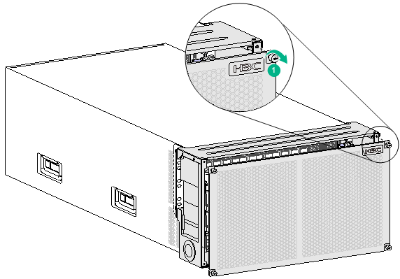
Installing the door
The door is secured to the jambs with four captive screws.
To install the door:
1. Place the door parallel to the front panel of the chassis.
2. Align two captive screws in a diagonal line on the door with the installation holes in the jambs and insert the screws part way into the installation holes.
3. Adjust the door position and insert the other two captive screws part way into the installation holes.
4. Fasten all captive screws.
Figure 25 Installing the door
Removing and cleaning the doors
Removing the doors
The removal procedure is the reverse of the installation procedure. When you remove the doors, follow these guidelines:
· To remove a hinged door, use a screwdriver to press the spring tab on the door. To avoid finger injury, do not use your fingers to press the spring tab.
· Keep the removed screws secure for future use.
Cleaning the doors
You need to clean the doors periodically. The cleaning interval depends on the equipment room condition. As a best practice, clean the doors every three months.
To clean the doors:
1. Remove the doors.
2. Use water to clean the doors and leave it to completely air dry.
3. Reinstall the doors. For the installation procedure, see "Installing the door kit."
Chassis air filter door kit views
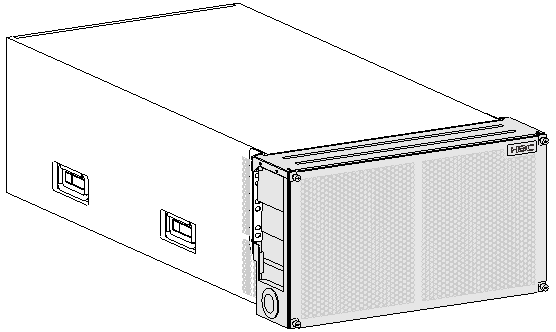
Figure 26 H3C chassis front air filter door kit applicable to the S12516X-AF/S12516F-AF, S12512X-AF/S12512F-AF, and S12508X-AF/S12508F-AF switches and CR19000-16, CR16016-X, and CR16008-X routers
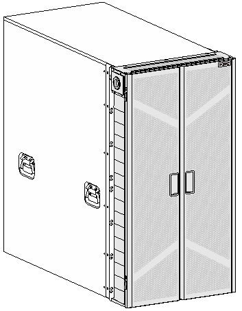
Figure 27 H3C chassis front air filter door kit applicable to the S12508XC-AF/S12508M-AF switch
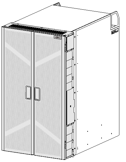
Figure 28 H3C chassis front air filter door kit applicable to the S12504X-AF/S12504F-AF switch