- Table of Contents
-
- 12-Network Management and Monitoring Configuration Guide
- 00-Preface
- 01-System maintenance and debugging configuration
- 02-NQA configuration
- 03-NTP configuration
- 04-PoE configuration
- 05-SNMP configuration
- 06-RMON configuration
- 07-NETCONF configuration
- 08-EAA configuration
- 09-Process monitoring and maintenance configuration
- 10-Sampler configuration
- 11-Mirroring configuration
- 12-NetStream configuration
- 13-IPv6 NetStream configuration
- 14-sFlow configuration
- 15-Information center configuration
- 16-GOLD configuration
- 17-Packet capture configuration
- 18-VCF fabric configuration
- Related Documents
-
| Title | Size | Download |
|---|---|---|
| 18-VCF fabric configuration | 128.42 KB |
Automated VCF fabric provisioning and deployment
Automated underlay network provisioning
Configuration restrictions and guidelines
VCF fabric configuration task list
Enabling VCF fabric topology discovery
Configuration restrictions and guidelines
Configuring automated underlay network provisioning
Configuration restrictions and guidelines
Displaying and maintaining VCF fabric
Configuring VCF fabric
Overview
IT infrastructure which comprises clouds, networks, and terminal devices is undergoing a deep transform. As terminal devices become more intelligentized and mobilized, the IT infrastructure is migrating to the cloud. It aims to implement the elastic expansion of computing resources and to provide IT services on demand. In this context, H3C develops the Virtual Converged Framework (VCF) technology. VCF breaks the boundaries between the networking, cloud management, and terminal platforms and converts the IT infrastructure to a converged framework to accommodate all applications. It also implements automatic network provisioning and deployment.
VCF fabric topology
In a VCF fabric, a device has one of the following roles:
· Spine node—Connects to leaf nodes.
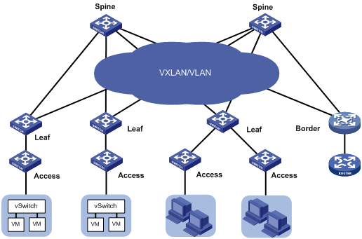
· Leaf node—As shown in Figure 1, a leaf node connects to a server in a typical data center network. A shown in Figure 2, a leaf node connects to an access node in a typical campus network.
· Access node—Connects to an upstream leaf node and downstream terminal devices.
· Border node—Located at the border of a VCF fabric to provide access to the external network.
Spine nodes and leaf nodes form a large Layer 2 network, which can be a VLAN, a VXLAN with centralized IP gateways, or a VXLAN with distributed IP gateways. For more information about centralized IP gateways and distributed IP gateways, see VXLAN Configuration Guide.
Figure 1 VCF fabric topology for a data center network
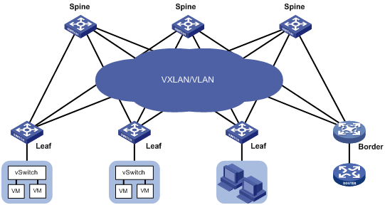
Figure 2 VCF fabric topology for a campus network
Automated VCF fabric provisioning and deployment
VCF provides the following features to ease deployment:
· Automatic topology discovery.
· Automated underlay network provisioning.
· Dynamic display of topology changes by using the H3C VCF fabric director.
Topology discovery
In a VCF fabric, each device uses LLDP to collect local topology information from directly-connected peer devices. The local topology information includes connection interfaces, roles, MAC addresses, and management interface addresses of the peer devices.
If multiple spine nodes exist in a VCF fabric, a master spine node is specified to collect the topology for the entire network.
Automated underlay network provisioning
An underlay network is a physical Layer 3 network.
Automated underlay network provisioning sets up a Layer 3 underlay network for users. It is implemented by automatically executing configurations (such as IRF configuration and Layer 3 reachability configurations) in user-defined template files.
Provisioning prerequisites
Before you start automated underlay network provisioning, complete the following tasks:
1. Finish the underlay network planning (such as IP address assignment, reliability design, and routing deployment) based on user requirements.
2. Configure the DHCP server and the TFTP server.
3. Upload startup image files to the TFTP server. Skip this step if all devices in the VCF fabric use the same startup image files and no software update is required.
4. Create template files for all device roles based on the topology type and upload the template files to the TFTP server. A template file is a file that ends with the .template file extension. The following are different template types:
? Template for a leaf node in a VLAN.
? Template for a leaf node in a VXLAN with centralized gateways.
? Template for a leaf node in a VXLAN with distributed gateways.
? Template for a spine node in a VLAN.
? Template for a spine node in a VXLAN with centralized gateways.
? Template for a spine node in a VXLAN with distributed gateways.
Process of automated underlay network provisioning
The device finishes automated underlay network provisioning as follows:
1. Starts up with factory configuration.
2. Obtains an IP address, the IP address of the TFTP server, and a template file name in the networktype.template format from the DHCP server.
3. Downloads a template file (named networktype_role.template) that corresponds with its device role from the TFTP server.
4. Parses the template file and executes the configurations in the template file.
|
|
NOTE: · If the template file contains software version information, the device first compares the software version with the current software version. If the two versions are inconsistent, the device downloads the new software version to perform software upgrade. After restarting up, the device executes the configurations in the template file. · If the template file does not include IRF configurations, the device does no save the configurations after executing all configurations in the template file. To save the configurations, use the save command. |
Template file
A template file contains the following contents:
· System-predefined variables—The variable names cannot be edited, and the variable values are set by the VCF topology discovery feature.
· User-defined variables—The variable names and values are defined by the user. These variables include the local username and password, network type, and so on. The following are examples of user-defined variables:
#USERDEF
_underlayIPRange = 10.100.0.0/16
_master_spine_mac = 1122-3344-5566
_backup_spine_mac = aabb-ccdd-eeff
_username = aaa
_password = aaa
_rbacUserRole = network-admin
_loghost_ip = 172.16.1.136
…
· Static configurations—Static configurations are independent from the VCF fabric topology and can be directly executed. The following are examples of static configurations:
#STATICCFG
#
clock timezone beijing add 08:00:00
#
lldp global enable
#
stp global enable
#
· Dynamic configurations—Dynamic configurations are dependent on the VCF fabric topology. The device first obtains the topology information and then executes dynamic configurations. The following are examples of dynamic configurations:
#
interface $$_underlayIntfDown
port link-mode route
ip address unnumbered interface LoopBack0
ospf 1 area 0.0.0.0
ospf network-type p2p
lldp management-address arp-learning
lldp tlv-enable basic-tlv management-address-tlv interface LoopBack0
#
Configuration restrictions and guidelines
Typically, the device completes automated underlay network provisioning by downloading and executing the template file. You do not need to manually configure the device by using commands.
VCF fabric configuration task list
|
Tasks at a glance |
|
(Required.) Enabling VCF fabric topology discovery |
|
(Optional.) Configuring automated underlay network provisioning |
Enabling VCF fabric topology discovery
Configuration restrictions and guidelines
VCF fabric topology discovery can be automatically enabled by executing configurations in the template file or be manually enabled at the CLI. The device uses LLDP to collect topology data of directly-connected devices. Make sure you have enabled LLDP on the device before you manually enable VCF fabric topology discovery.
Configuration procedure
|
Step |
Command |
Remarks |
|
1. Enter system view. |
system-view |
N/A |
|
2. Enable LLDP globally. |
lldp global enable |
By default, LLDP is disabled globally. |
|
3. Enable VCF fabric topology discovery. |
vcf-fabric topology enable |
By default, VCF fabric topology discovery is disabled. |
Configuring automated underlay network provisioning
Configuration restrictions and guidelines
When you configure automated underlay network provisioning, follow these restrictions and guidelines:
· Automated underlay network configuration can be automatically completed after the device starts up. If you need to change the automated underlay network provision on a running device, you can download the new template file through TFTP. Then, execute the vcf-fabric underlay autoconfigure command to manually specify the template file on the device.
· As a best practice, do not modify the network type or the device role while the device is running. If it is necessary to do so, make sure you understand the impacts on the network and services.
· If you change the role of the device, the new role takes effect after the device restarts up.
Configuration procedure
|
Step |
Command |
Remarks |
|
1. Enter system view. |
system-view |
N/A |
|
2. (Optional.) Specify the role of the device in the VCF fabric. |
vcf-fabric role { access | leaf | spine } |
By default, no role is specified for the device. |
|
3. Specify the template file for automated underlay network provisioning. |
vcf-fabric underlay autoconfigure template |
By default, no template file is specified for automated underlay network provisioning. |
|
4. (Optional.) Pause automated underlay network provisioning. |
vcf-fabric underlay pause |
By default, automated underlay network provisioning is not paused. |
|
5. (Optional.) Configure the device as a master spine node. |
vcf-fabric spine-role master |
By default, the device is not a master spine node. |
Displaying and maintaining VCF fabric
Execute display commands in any view.
|
Task |
Command |
|
Display VCF fabric topology information. |
display vcf-fabric topology |
|
Display information about automated underlay network provisioning. |
display vcf-fabric underlay autoconfigure |
Automated VCF fabric configuration example
Network requirements
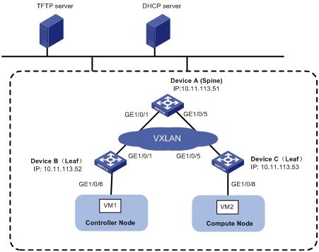
As shown in Figure 3, Devices A, B, and C all connect to the TFTP server and the DHCP server through management Ethernet interfaces. VM 1 resides on the controller node. VM 2 resides on the compute node. The controller node runs OpenStack Kilo version and Ubuntu14.04 LTS operating system.
Configure a VCF fabric to meet the following requirements:
· The VCF fabric is a VXLAN network deployed on spine node Device A and leaf nodes Device B and Device C to provide connectivity between VM 1 and VM 2. Device A acts as a centralized VXLAN IP gateway.
· Devices A, B, and C complete automated underlay network provisioning by using template files after they start up.
· The DHCP server dynamically assigns IP addresses on subnet 10.11.113.0/24.
Configuration procedure
Configuring the DHCP server
Perform the following tasks on the DHCP server:
1. Configure a DHCP address pool to dynamically assign IP addresses on subnet 10.11.113.0/24 to the devices.
2. Specify the IP address of the TFTP server as 10.11.113.19/24.
3. Specify a template file as the boot file. A template file is named as networktype.template, for example, "vxlan.template".
Creating template files
Create template files and upload them to the TFTP server.
Typically, a template file includes the following contents:
· System-predefined variables—Internally used by the system. User-defined variables cannot be the same as system-predefined variables.
· User-defined variables—Defined by the user. User-defined variables include basic settings, such as local username and password, user role, and so on.
· Software images for upgrade and the URL to download the software images.
· Configuration commands—Include commands independent from the topology (such as LLDP, NTP, and SNMP) and commands dependent on the topology (such as interfaces settings).
Configuring the TFTP server
Place the template files on the TFTP server. In this example, both spine node and leaf node exist on the VXLAN network, so two template files (vxlan_spine.template and vxlan_leaf.template) are required.
Powering up Device A, Device B, and Device C
After starting up with factory configuration, Device A, Device B, and Device C each automatically downloads a template file to finish automated underlay network provisioning.
Verifying the configuration
Verifying the collected topology of the underlay network
# Display VCF fabric topology information on Device A.
[DeviceA] display vcf-fabric topology
Topology Information
----------------------------------------------------------------------------------
* indicates the master spine role among all spines
SpineIP Interface Link LeafIP Status
*10.11.113.51 GigabitEthernet1/0/1 Up 10.11.113.52 Running
GigabitEthernet1/0/2 Down -- --
GigabitEthernet1/0/3 Down -- --
GigabitEthernet1/0/4 Down -- --
GigabitEthernet1/0/5 Up 10.11.113.53 Running
GigabitEthernet1/0/6 Down -- --
GigabitEthernet1/0/7 Down -- --
GigabitEthernet1/0/8 Down -- --
Verifying the automated configuration for the underlay network
# Display information about automated underlay network provisioning on Device A.
[DeviceA] display vcf-fabric underlay autoconfigure
success command:
#
system
clock timezone beijing add 08:00:00
#
system
lldp global enable
#
system
stp global enable
#
system
ospf 1
graceful-restart ietf
area 0.0.0.0
#
system
interface LoopBack0
#
system
ip vpn-instance global
route-distinguisher 1:1
vpn-target 1:1 import-extcommunity
#
system
l2vpn enable
#
system
vxlan tunnel mac-learning disable
vxlan tunnel arp-learning disable
#
system
ntp-service enable
ntp-service unicast-peer 10.11.113.136
#
system
netconf soap http enable
netconf soap https enable
restful http enable
restful https enable
#
system
ip http enable
ip https enable
#
system
telnet server enable
#
system
info-center loghost 10.11.113.136
#
system
local-user aaa
password ******
service-type telnet http https
service-type ssh
authorization-attribute user-role network-admin
#
system
line vty 0 63
authentication-mode scheme
user-role network-admin
#
system
bgp 100
graceful-restart
address-family l2vpn evpn
undo policy vpn-target
#
system
vcf-fabric topology enable
#
system
snmp-agent
snmp-agent community read public
snmp-agent community write private
snmp-agent sys-info version all
#interface up-down:
GigabitEthernet1/0/1
GigabitEthernet1/0/5
Loopback0 IP Allocation:
DEV_MAC LOOPBACK_IP MANAGE_IP STATE
a43c-adae-0400 10.100.16.17 10.11.113.53 up
a43c-9aa7-0100 10.100.16.15 10.11.113.51 up
a43c-a469-0300 10.100.16.16 10.11.113.52 up
IRF Allocation:
Self Bridge Mac: a43c-9aa7-0100
IRF Status: No
Member List: [1]
bgp configure peer:
10.100.16.17
10.100.16.16