- Table of Contents
-
- 06-Layer 3 - IP Routing Configuration Guide
- 00-Preface
- 01-Basic IP routing configuration
- 02-Static routing configuration
- 03-RIP configuration
- 04-OSPF configuration
- 05-IS-IS configuration
- 06-BGP configuration
- 07-Policy-based routing configuration
- 08-IPv6 static routing configuration
- 09-RIPng configuration
- 10-OSPFv3 configuration
- 11-IPv6 IS-IS configuration
- 12-IPv6 policy-based routing configuration
- 13-Routing policy configuration
- Related Documents
-
| Title | Size | Download |
|---|---|---|
| 09-RIPng configuration | 169.84 KB |
Configuring RIPng route control
Configuring an additional routing metric
Configuring RIPng route summarization·
Configuring received/redistributed route filtering
Setting a preference for RIPng
Configuring RIPng route redistribution·
Tuning and optimizing the RIPng network
Configuring split horizon and poison reverse
Configuring zero field check on RIPng packets
Setting the maximum number of ECMP routes
Displaying and maintaining RIPng
Basic RIPng configuration example
RIPng route redistribution configuration example
RIPng IPsec profile configuration example
Configuring RIPng
Overview
RIP next generation (RIPng) is an extension of RIP-2 for support of IPv6. Most RIP concepts are applicable to RIPng.
RIPng is a distance vector routing protocol. It employs UDP to exchange route information through port 521. RIPng uses a hop count to measure the distance to a destination. The hop count is the metric or cost. The hop count from a router to a directly connected network is 0. The hop count between two directly connected routers is 1. When the hop count is greater than or equal to 16, the destination network or host is unreachable.
By default, the routing update is sent every 30 seconds. If the router receives no routing updates from a neighbor within 180 seconds, the routes learned from the neighbor are considered unreachable. If no routing update is received within another 240 seconds, the router removes these routes from the routing table.
RIPng for IPv6 has the following differences from RIP:
· UDP port number—RIPng uses UDP port 521 to send and receive routing information.
· Multicast address—RIPng uses FF02::9 as the link-local-router multicast address.
· Destination Prefix—128-bit destination address prefix.
· Next hop—128-bit IPv6 address.
· Source address—RIPng uses FE80::/10 as the link-local source address.
RIPng route entries
RIPng stores route entries in a database. Each route entry contains the following elements:
· Destination address—IPv6 address of a destination host or a network.
· Next hop address—IPv6 address of the next hop.
· Egress interface—Egress interface of the route.
· Metric—Cost from the local router to the destination.
· Route time—Time elapsed since the most recent update. The time is reset to 0 every time the route entry is updated.
· Route tag—Used for route control. For more information, see "Configuring routing policies."
RIPng packets
RIPng uses request and response packets to exchange routing information as follows:
1. When RIPng starts or needs to update some route entries, it sends a multicast request packet to neighbors.
2. When a RIPng neighbor receives the request packet, it sends back a response packet that contains the local routing table. RIPng can also advertise route updates in response packets periodically or advertise a triggered update caused by a route change.
3. After RIPng receives the response, it checks the validity of the response before adding routes to its routing table, including the following details:
¡ Whether the source IPv6 address is the link-local address.
¡ Whether the port number is correct.
4. A response packet that fails the check is discarded.
Protocols and standards
· RFC 2080, RIPng for IPv6
· RFC 2081, RIPng Protocol Applicability Statement
RIPng configuration task list
|
Tasks at a glance |
|
(Required.) Configuring basic RIPng |
|
(Optional.) Configuring RIPng route control: · Configuring an additional routing metric · Configuring RIPng route summarization · Configuring received/redistributed route filtering |
|
(Optional.) Tuning and optimizing the RIPng network: · Configuring split horizon and poison reverse |
|
(Optional.) Configuring RIPng GR |
|
(Optional.) Applying an IPsec profile |
Configuring basic RIPng
Before you configure basic RIPng, configure IPv6 addresses for interfaces to ensure IPv6 connectivity between neighboring nodes.
To configure basic RIPng:
|
Command |
Remarks |
|
|
1. Enter system view. |
system-view |
N/A |
|
2. Create a RIPng process and enter its view. |
ripng [ process-id ] [ vpn-instance vpn-instance-name ] |
By default, the RIPng process is not created. |
|
3. Return to system view. |
quit |
N/A |
|
4. Enter interface view. |
interface interface-type interface-number |
N/A |
|
5. Enable RIPng on the interface. |
ripng process-id enable |
By default, RIPng is disabled. If RIPng is not enabled on an interface, the interface does not send or receive any RIPng route. |
Configuring RIPng route control
Before you configure RIPng, complete the following tasks:
· Configure IPv6 addresses for interfaces to ensure IPv6 connectivity between neighboring nodes.
· Configure basic RIPng.
Configuring an additional routing metric
An additional routing metric (hop count) can be added to the metric of an inbound or outbound RIPng route.
An outbound additional metric is added to the metric of a sent route, and it does not change the route's metric in the routing table.
An inbound additional metric is added to the metric of a received route before the route is added into the routing table, and the route's metric is changed.
To configure an inbound or outbound additional routing metric:
|
Command |
Remarks |
|
|
1. Enter system view. |
system-view |
N/A |
|
2. Enter interface view. |
interface interface-type interface-number |
N/A |
|
3. Specify an inbound additional routing metric. |
ripng metricin value |
The default setting is 0. |
|
4. Specify an outbound additional routing metric. |
ripng metricout value |
The default setting is 1. |
Configuring RIPng route summarization
Configure route summarization on an interface, so RIPng advertises a summary route based on the longest match.
RIPng route summarization improves network scalability, reduces routing table size, and increases routing table lookup efficiency.
RIPng advertises a summary route with the smallest metric of all the specific routes.
For example, RIPng has two specific routes to be advertised through an interface: 1:11:11::24 with a metric of a 2 and 1:11:12::34 with a metric of 3. Configure route summarization on the interface, so RIPng advertises a single route 11::0/16 with a metric of 2.
To configure RIPng route summarization:
|
Step |
Command |
Remarks |
|
1. Enter system view. |
system-view |
N/A |
|
2. Enter interface view. |
interface interface-type interface-number |
N/A |
|
3. Advertise a summary IPv6 prefix. |
ripng summary-address ipv6-address prefix-length |
By default, the summary IPv6 prefix is not configured. |
Advertising a default route
You can configure RIPng to advertise a default route with the specified cost to its neighbors.
To configure RIPng to advertise a default route:
|
Step |
Command |
Remarks |
|
1. Enter system view. |
system-view |
N/A |
|
2. Enter interface view. |
interface interface-type interface-number |
N/A |
|
3. Configure RIPng to advertise a default route. |
ripng default-route { only | originate } [ cost cost ] |
By default, RIPng does not advertise a default route. This command advertises a default route on the current interface regardless of whether the default route exists in the local IPv6 routing table. |
Configuring received/redistributed route filtering
Perform this task to filter received or redistributed routes by using an IPv6 ACL or IPv6 prefix list. You can also configure RIPng to filter routes redistributed from other routing protocols and routes from a specified neighbor.
To configure a RIPng route filtering policy:
|
Step |
Command |
Remarks |
|
1. Enter system view. |
system-view |
N/A |
|
2. Enter RIPng view. |
ripng [ process-id ] [ vpn-instance vpn-instance-name ] |
N/A |
|
3. Configure a filter policy to filter received routes. |
filter-policy { acl6-number | prefix-list prefix-list-name } import |
By default, RIPng does not filter received routes. |
|
4. Configure a filter policy to filter redistributed routes. |
filter-policy { acl6-number | prefix-list prefix-list-name } export [ protocol [ process-id ] ] |
By default, RIPng does not filter redistributed routes. |
Setting a preference for RIPng
Routing protocols each have a preference. When they find routes to the same destination, the route found by the routing protocol with the highest preference is selected as the optimal route. You can manually set a preference for RIPng. The smaller the value, the higher the preference.
To set a preference for RIPng:
|
Step |
Command |
Remarks |
|
1. Enter system view. |
system-view |
N/A |
|
2. Enter RIPng view. |
ripng [ process-id ] [ vpn-instance vpn-instance-name ] |
N/A |
|
3. Set a preference for RIPng. |
preference [ route-policy route-policy-name ] value |
By default, the preference of RIPng is 100. |
Configuring RIPng route redistribution
|
Step |
Command |
Remarks |
|
1. Enter system view. |
system-view |
N/A |
|
2. Enter RIPng view. |
ripng [ process-id ] [ vpn-instance vpn-instance-name ] |
N/A |
|
3. Redistribute routes from other routing protocols. |
import-route protocol [ process-id ] [ allow-ibgp ] [ cost cost | route-policy route-policy-name ] * |
By default, RIPng does not redistribute routes from other routing protocols. |
|
4. (Optional.) Set a default routing metric for redistributed routes. |
default cost cost |
The default metric of redistributed routes is 0. |
Tuning and optimizing the RIPng network
This section describes how to tune and optimize the performance of the RIPng network as well as applications under special network environments.
Before you tune and optimize the RIPng network, complete the following tasks:
· Configure IPv6 addresses for interfaces to ensure IPv6 connectivity between neighboring nodes.
· Configure basic RIPng.
Setting RIPng timers
You can adjust RIPng timers to optimize the performance of the RIPng network.
When you adjust RIPng timers, consider the network performance, and perform unified configurations on routers running RIPng to avoid unnecessary network traffic or route oscillation.
To set RIPng timers:
|
Step |
Command |
Remarks |
|
1. Enter system view. |
system-view |
N/A |
|
2. Enter RIPng view. |
ripng [ process-id ] [ vpn-instance vpn-instance-name ] |
N/A |
|
3. Set RIPng timers. |
timers { garbage-collect garbage-collect-value | suppress suppress-value | timeout timeout-value | update update-value } * |
By default: · The update timer is 30 seconds. · The timeout timer is 180 seconds. · The suppress timer is 120 seconds. · The garbage-collect timer is 120 seconds. |
Configuring split horizon and poison reverse
If both split horizon and poison reverse are configured, only the poison reverse function takes effect.
Configuring split horizon
Split horizon disables RIPng from sending routes through the interface where the routes were learned to prevent routing loops between neighbors.
As a best practice, enable split horizon to prevent routing loops in normal cases.
To configure split horizon:
|
Step |
Command |
Remarks |
|
1. Enter system view. |
system-view |
N/A |
|
2. Enter interface view. |
interface interface-type interface-number |
N/A |
|
3. Enable split horizon. |
ripng split-horizon |
By default, split horizon is enabled. |
Configuring poison reverse
Poison reverse enables a route learned from an interface to be advertised through the interface. However, the metric of the route is set to 16, which means the route is unreachable.
To configure poison reverse:
|
Step |
Command |
Remarks |
|
1. Enter system view. |
system-view |
N/A |
|
2. Enter interface view. |
interface interface-type interface-number |
N/A |
|
3. Enable poison reverse. |
ripng poison-reverse |
By default, poison reverse is disabled. |
Configuring zero field check on RIPng packets
Some fields in the RIPng packet header must be zero. These fields are called zero fields. You can enable zero field check on incoming RIPng packets. If a zero field of a packet contains a non-zero value, RIPng does not process the packets. If you are certain that all packets are trustworthy, disable the zero field check to save CPU resources.
To configure RIPng zero field check:
|
Step |
Command |
Remarks |
|
1. Enter system view. |
system-view |
N/A |
|
2. Enter RIPng view. |
ripng [ process-id ] [ vpn-instance vpn-instance-name ] |
N/A |
|
3. Enable the zero field check on incoming RIPng packets. |
checkzero |
By default, this feature is enabled. |
Setting the maximum number of ECMP routes
|
Step |
Command |
Remarks |
|
1. Enter system view. |
system-view |
N/A |
|
2. Enter RIPng view. |
ripng [ process-id ] [ vpn-instance vpn-instance-name ] |
N/A |
|
3. Set the maximum number of ECMP routes. |
maximum load-balancing number |
By default, the maximum number of ECMP routes equals the maximum number of ECMP routes supported by the system. |
Configuring RIPng GR
Two routers are required to complete a GR process. The following are router roles in a GR process:
· GR restarter—Graceful restarting router. It must have GR capability.
· GR helper—A neighbor of the GR restarter. It helps the GR restarter to complete the GR process.
After RIPng restarts on a router, the router must learn RIPng routes again and updates its FIB table, which causes network disconnections and route reconvergence.
With the GR feature, the restarting router (known as the GR restarter) can notify the event to its GR capable neighbors. GR capable neighbors (known as GR helpers) maintain their adjacencies with the router within a configurable GR interval. During this process, the FIB table of the router does not change. After the restart, the router contacts its neighbors to retrieve its FIB.
By default, a RIPng-enabled device acts as the GR helper. Perform this task on the GR restarter.
To configure GR on the GR restarter:
|
Step |
Command |
Remarks |
|
1. Enter system view. |
system-view |
N/A |
|
2. Enable RIPng and enter RIPng view. |
ripng [ process-id ] [ vpn-instance vpn-instance-name ] |
N/A |
|
3. Enable the GR capability for RIPng. |
graceful-restart |
By default, RIPng GR is disabled. |
Applying an IPsec profile
To protect routing information and prevent attacks, RIPng supports using an IPsec profile to authenticate protocol packets. For more information about IPsec profiles, see Security Configuration Guide.
Outbound RIPng packets carry the Security Parameter Index (SPI) defined in the relevant IPsec profile. A device compares the SPI carried in a received packet with the configured IPsec profile. If they match, the device accepts the packet. If they do not match, the device discards the packet and does not establish a neighbor relationship with the sending device.
You can configure an IPsec profile for a RIPng process or interface. The IPsec profile configured for a process applies to all packets in the process. The IPsec profile configured for an interface applies to packets on the interface. If an interface and its process each have an IPsec profile configured, the IPsec profile configured for the interface takes effect.
To apply an IPsec profile to a process:
|
Step |
Command |
Remarks |
|
1. Enter system view. |
system-view |
N/A |
|
2. Enter RIPng view. |
ripng [ process-id ] [ vpn-instance vpn-instance-name ] |
N/A |
|
3. Apply an IPsec profile to the process. |
enable ipsec-profile profile-name |
By default, no IPsec profile is applied. |
To apply an IPsec profile to an interface:
|
Step |
Command |
Remarks |
|
1. Enter system view. |
system-view |
N/A |
|
2. Enter interface view. |
interface interface-type interface-number |
N/A |
|
3. Apply an IPsec profile to the interface. |
ripng ipsec-profile profile-name |
By default, no IPsec profile is applied. |
Displaying and maintaining RIPng
Execute display commands in any view and reset commands in user view.
|
Task |
Command |
|
Display configuration information for a RIPng process. |
display ripng [ process-id ] |
|
Display routes in the RIPng database. |
display ripng process-id database [ ipv6-address prefix-length ] |
|
Display interface information for a RIPng process. |
display ripng process-id interface [ interface-type interface-number ] |
|
Display the routing information for a RIPng process. |
display ripng process-id route [ ipv6-address prefix-length [ verbose ] | peer ipv6-address | statistics ] |
|
Restart a RIPng process. |
reset ripng process-id process |
|
Clear statistics for a RIPng process. |
reset ripng process-id statistics |
RIPng configuration examples
Basic RIPng configuration example
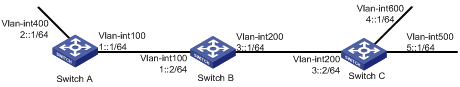
Network requirements
As shown in Figure 1, Switch A, Switch B, and Switch C run RIPng. Configure Switch B to filter the route 2::/64 learned from Switch A and to forward only the route 4::/64 to Switch A.
Configuration procedure
1. Configure IPv6 addresses for interfaces. (Details not shown.)
2. Configure basic RIPng:
# Configure Switch A.
<SwitchA> system-view
[SwitchA] ripng 1
[SwitchA-ripng-1] quit
[SwitchA] interface vlan-interface 100
[SwitchA-Vlan-interface100] ripng 1 enable
[SwitchA-Vlan-interface100] quit
[SwitchA] interface vlan-interface 400
[SwitchA-Vlan-interface400] ripng 1 enable
[SwitchA-Vlan-interface400] quit
# Configure Switch B.
<SwitchA> system-view
[SwitchA] ripng 1
[SwitchA-ripng-1] quit
[SwitchA] interface vlan-interface 100
[SwitchA-Vlan-interface100] ripng 1 enable
[SwitchA-Vlan-interface100] quit
[SwitchA] interface vlan-interface 400
[SwitchA-Vlan-interface400] ripng 1 enable
[SwitchA-Vlan-interface400] quit
# Configure Switch C.
<SwitchC> system-view
[SwitchC] ripng 1
[SwitchC-ripng-1] quit
[SwitchC] interface vlan-interface 200
[SwitchC-Vlan-interface200] ripng 1 enable
[SwitchC-Vlan-interface200] quit
[SwitchC] interface vlan-interface 500
[SwitchC-Vlan-interface500] ripng 1 enable
[SwitchC-Vlan-interface500] quit
[SwitchC] interface vlan-interface 600
[SwitchC-Vlan-interface600] ripng 1 enable
[SwitchC-Vlan-interface600] quit
# Display the RIPng routing table on Switch B.
[SwitchB] display ripng 1 route
Route Flags: A - Aging, S - Suppressed, G - Garbage-collect
O - Optimal, F - Flush to RIB
----------------------------------------------------------------
Peer FE80::20F:E2FF:FE23:82F5 on Vlan-interface100
Destination 2::/64,
via FE80::20F:E2FF:FE23:82F5, cost 1, tag 0, AOF, 6 secs
Local route
Destination 1::/64,
via ::, cost 0, tag 0, DOF
Peer FE80::20F:E2FF:FE00:100 on Vlan-interface200
Destination 4::/64,
via FE80::20F:E2FF:FE00:100, cost 1, tag 0, AOF, 11 secs
Destination 5::/64,
via FE80::20F:E2FF:FE00:100, cost 1, tag 0, AOF, 11
Local route
Destination 3::/64,
via ::, cost 0, tag 0, DOF
# Display the RIPng routing table on Switch A.
[SwitchA] display ripng 1 route
Route Flags: A - Aging, S - Suppressed, G - Garbage-collect
O - Optimal, F - Flush to RIB
----------------------------------------------------------------
Peer FE80::200:2FF:FE64:8904 on Vlan-interface100
Destination 3::/64,
via FE80::200:2FF:FE64:8904, cost 1, tag 0, AOF, 31 secs
Destination 4::/64,
via FE80::200:2FF:FE64:8904, cost 2, tag 0, AOF, 31 secs
Destination 5::/64,
via FE80::200:2FF:FE64:8904, cost 2, tag 0, AOF, 31 secs
Local route
Destination 1::/64,
via ::, cost 0, tag 0, DOF
3. Configure route filtering:
# Use IPv6 prefix lists on Switch B to filter received and redistributed routes.
[SwitchB] ipv6 prefix-list aaa permit 4:: 64
[SwitchB] ipv6 prefix-list bbb deny 2:: 64
[SwitchB] ipv6 prefix-list bbb permit :: 0 less-equal 128
[SwitchB] ripng 1
[SwitchB-ripng-1] filter-policy prefix-list aaa export
[SwitchB-ripng-1] filter-policy prefix-list bbb import
[SwitchB-ripng-1] quit
# Display RIPng routing tables on Switch B and Switch A.
[SwitchB] display ripng 1 route
Route Flags: A - Aging, S - Suppressed, G - Garbage-collect
O - Optimal, F - Flush to RIB
----------------------------------------------------------------
Peer FE80::1:100 on Vlan-interface100
Peer FE80::3:200 on Vlan-interface200
Destination 4::/64,
via FE80::2:200, cost 1, tag 0, AOF, 11 secs
Destination 5::/64,
via FE80::2:200, cost 1, tag 0, AOF, 11 secs
Local route
Destination 1::/64,
via ::, cost 0, tag 0, DOF
Destination 3::/64,
via ::, cost 0, tag 0, DOF
[SwitchA] display ripng 1 route
Route Flags: A - Aging, S - Suppressed, G - Garbage-collect
O - Optimal, F - Flush to RIB
----------------------------------------------------------------
Peer FE80::2:100 on Vlan-interface100
Destination 4::/64,
via FE80::1:100, cost 2, tag 0, AOF, 2 secs
RIPng route redistribution configuration example
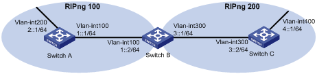
Network requirements
As shown in Figure 2, Switch B communicates with Switch A through RIPng 100 and with Switch C through RIPng 200.
Configure route redistribution on Switch B, so the two RIPng processes can redistribute routes from each other.
Configuration procedure
1. Configure IPv6 addresses for interfaces. (Details not shown.)
2. Configure basic RIPng:
# Enable RIPng 100 on Switch A.
<SwitchA> system-view
[SwitchA] ripng 100
[SwitchA-ripng-100] quit
[SwitchA] interface vlan-interface 100
[SwitchA-Vlan-interface100] ripng 100 enable
[SwitchA-Vlan-interface100] quit
[SwitchA] interface vlan-interface 200
[SwitchA-Vlan-interface200] ripng 100 enable
[SwitchA-Vlan-interface200] quit
# Enable RIPng 100 and RIPng 200 on Switch B.
<SwitchB> system-view
[SwitchB] ripng 100
[SwitchB-ripng-100] quit
[SwitchB] interface vlan-interface 100
[SwitchB-Vlan-interface100] ripng 100 enable
[SwitchB-Vlan-interface100] quit
[SwitchB] ripng 200
[SwitchB-ripng-200] quit
[SwitchB] interface vlan-interface 300
[SwitchB-Vlan-interface300] ripng 200 enable
[SwitchB-Vlan-interface300] quit
# Enable RIPng 200 on Switch C.
<SwitchC> system-view
[SwitchC] ripng 200
[SwitchC] interface vlan-interface 300
[SwitchC-Vlan-interface300] ripng 200 enable
[SwitchC-Vlan-interface300] quit
[SwitchC] interface vlan-interface 400
[SwitchC-Vlan-interface400] ripng 200 enable
[SwitchC-Vlan-interface400] quit
# Display the routing table on Switch A.
[SwitchA] display ipv6 routing-table
Destinations : 7 Routes : 7
Destination: ::1/128 Protocol : Direct
NextHop : ::1 Preference: 0
Interface : InLoop0 Cost : 0
Destination: 1::/64 Protocol : Direct
NextHop : 1::1 Preference: 0
Interface : Vlan100 Cost : 0
Destination: 1::1/128 Protocol : Direct
NextHop : ::1 Preference: 0
Interface : InLoop0 Cost : 0
Destination: 2::/64 Protocol : Direct
NextHop : 2::1 Preference: 0
Interface : Vlan200 Cost : 0
Destination: 2::1/128 Protocol : Direct
NextHop : ::1 Preference: 0
Interface : InLoop0 Cost : 0
Destination: FE80::/10 Protocol : Direct
NextHop : :: Preference: 0
Interface : NULL0 Cost : 0
Destination: FF00::/8 Protocol : Direct
NextHop : :: Preference: 0
Interface : NULL0 Cost : 0
3. Configure RIPng route redistribution:
# Configure route redistribution between the two RIPng processes on Switch B.
[SwitchB] ripng 100
[SwitchB-ripng-100] import-route ripng 200
[SwitchB-ripng-100] quit
[SwitchB] ripng 200
[SwitchB-ripng-200] import-route ripng 100
[SwitchB-ripng-200] quit
# Display the routing table on Switch A.
[SwitchA] display ipv6 routing-table
Destinations : 8 Routes : 8
Destination: ::1/128 Protocol : Direct
NextHop : ::1 Preference: 0
Interface : InLoop0 Cost : 0
Destination: 1::/64 Protocol : Direct
NextHop : 1::1 Preference: 0
Interface : Vlan100 Cost : 0
Destination: 1::1/128 Protocol : Direct
NextHop : ::1 Preference: 0
Interface : InLoop0 Cost : 0
Destination: 2::/64 Protocol : Direct
NextHop : 2::1 Preference: 0
Interface : Vlan200 Cost : 0
Destination: 2::1/128 Protocol : Direct
NextHop : ::1 Preference: 0
Interface : InLoop0 Cost : 0
Destination: 4::/64 Protocol : RIPng
NextHop : FE80::200:BFF:FE01:1C02 Preference: 100
Interface : Vlan100 Cost : 1
Destination: FE80::/10 Protocol : Direct
NextHop : :: Preference: 0
Interface : NULL0 Cost : 0
Destination: FF00::/8 Protocol : Direct
NextHop : :: Preference: 0
Interface : NULL0 Cost : 0
RIPng IPsec profile configuration example
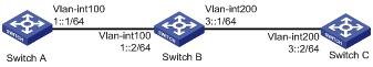
Network requirements
As shown in Figure 3, configure RIPng on the switches, and configure IPsec profiles on the switches to authenticate and encrypt protocol packets.
Configuration procedure
1. Configure IPv6 addresses for interfaces. (Details not shown.)
2. Configure RIPng basic functions:
# Configure Switch A.
<SwitchA> system-view
[SwitchA] ripng 1
[SwitchA-ripng-1] quit
[SwitchA] interface vlan-interface 100
[SwitchA-Vlan-interface100] ripng 1 enable
[SwitchA-Vlan-interface100] quit
# Configure Switch B.
<SwitchB> system-view
[SwitchB] ripng 1
[SwitchB-ripng-1] quit
[SwitchB] interface vlan-interface 200
[SwitchB-Vlan-interface200] ripng 1 enable
[SwitchB-Vlan-interface200] quit
[SwitchB] interface vlan-interface 100
[SwitchB-Vlan-interface100] ripng 1 enable
[SwitchB-Vlan-interface100] quit
# Configure Switch C.
<SwitchC> system-view
[SwitchC] ripng 1
[SwitchC-ripng-1] quit
[SwitchC] interface vlan-interface 200
[SwitchC-Vlan-interface200] ripng 1 enable
[SwitchC-Vlan-interface200] quit
3. Configure RIPng IPsec profiles:
¡ On Switch A:
# Create an IPsec transform set named protrf1.
[SwitchA] ipsec transform-set protrf1
# Specify the ESP encryption and authentication algorithms.
[SwitchA-ipsec-transform-set-protrf1] esp encryption-algorithm 3des-cbc
[SwitchA-ipsec-transform-set-protrf1] esp authentication-algorithm md5
# Specify the encapsulation mode as transport.
[SwitchA-ipsec-transform-set-protrf1] encapsulation-mode transport
[SwitchA-ipsec-transform-set-protrf1] quit
# Create a manual IPsec profile named profile001.
[SwitchA] ipsec profile profile001 manual
# Reference the IPsec transform set protrf1.
[SwitchA-ipsec-profile-profile001-manual] transform-set protrf1
# Configure the inbound and outbound SPIs for ESP.
[SwitchA-ipsec-profile-profile001-manual] sa spi inbound esp 256
[SwitchA-ipsec-profile-profile001-manual] sa spi outbound esp 256
# Configure the inbound and outbound SA keys for ESP.
[SwitchA-ipsec-profile-profile001-manual] sa string-key inbound esp simple abc
[SwitchA-ipsec-profile-profile001-manual] sa string-key outbound esp simple abc
[SwitchA-ipsec-profile-profile001-manual] quit
¡ On Switch B:
# Create an IPsec transform set named protrf1.
[SwitchB] ipsec transform-set protrf1
# Specify the ESP encryption and authentication algorithms.
[SwitchB-ipsec-transform-set-protrf1] esp encryption-algorithm 3des-cbc
[SwitchB-ipsec-transform-set-protrf1] esp authentication-algorithm md5
# Specify the encapsulation mode as transport.
[SwitchB-ipsec-transform-set-protrf1] encapsulation-mode transport
[SwitchB-ipsec-transform-set-protrf1] quit
# Create a manual IPsec profile named profile001.
[SwitchB] ipsec profile profile001 manual
# Reference the IPsec transform set protrf1.
[SwitchB-ipsec-profile-profile001-manual] transform-set protrf1
# Configure the inbound and outbound SPIs for ESP.
[SwitchB-ipsec-profile-profile001-manual] sa spi inbound esp 256
[SwitchB-ipsec-profile-profile001-manual] sa spi outbound esp 256
# Configure the inbound and outbound SA keys for ESP.
[SwitchB-ipsec-profile-profile001-manual] sa string-key inbound esp simple abc
[SwitchB-ipsec-profile-profile001-manual] sa string-key outbound esp simple abc
[SwitchB-ipsec-profile-profile001-manual] quit
¡ On Switch C:
# Create an IPsec transform set named protrf1.
[SwitchC] ipsec transform-set protrf1
# Specify the ESP encryption and authentication algorithms.
[SwitchC-ipsec-transform-set-protrf1] esp encryption-algorithm 3des-cbc
[SwitchC-ipsec-transform-set-protrf1] esp authentication-algorithm md5
# Specify the encapsulation mode as transport.
[SwitchC-ipsec-transform-set-protrf1] encapsulation-mode transport
[SwitchC-ipsec-transform-set-protrf1] quit
# Create a manual IPsec profile named profile001.
[SwitchC] ipsec profile profile001 manual
# Reference the IPsec transform set protrf1.
[SwitchC-ipsec-profile-profile001-manual] transform-set protrf1
# Configure the inbound and outbound SPIs for ESP.
[SwitchC-ipsec-profile-profile001-manual] sa spi inbound esp 256
[SwitchC-ipsec-profile-profile001-manual] sa spi outbound esp 256
# Configure the inbound and outbound SA keys for ESP.
[SwitchC-ipsec-profile-profile001-manual] sa string-key inbound esp simple abc
[SwitchC-ipsec-profile-profile001-manual] sa string-key outbound esp simple abc
[SwitchC-ipsec-profile-profile001-manual] quit
4. Apply the IPsec profiles to the RIPng process:
# Configure Switch A.
[SwitchA] ripng 1
[SwitchA-ripng-1] enable ipsec-profile profile001
[SwitchA-ripng-1] quit
# Configure Switch B.
[SwitchB] ripng 1
[SwitchB-ripng-1] enable ipsec-profile profile001
[SwitchB-ripng-1] quit
# Configure Switch C.
[SwitchC] ripng 1
[SwitchC-ripng-1] enable ipsec-profile profile001
[SwitchC-ripng-1] quit
Verifying the configuration
# Verify that RIPng packets between Switches A, B and C are protected by IPsec. (Details not shown.)