- Table of Contents
-
- 06-Layer 3 - IP Routing Configuration Guide
- 00-Preface
- 01-Basic IP routing configuration
- 02-Static routing configuration
- 03-RIP configuration
- 04-OSPF configuration
- 05-IS-IS configuration
- 06-BGP configuration
- 07-Policy-based routing configuration
- 08-IPv6 static routing configuration
- 09-RIPng configuration
- 10-OSPFv3 configuration
- 11-IPv6 IS-IS configuration
- 12-IPv6 policy-based routing configuration
- 13-Routing policy configuration
- Related Documents
-
| Title | Size | Download |
|---|---|---|
| 11-IPv6 IS-IS configuration | 148.41 KB |
Configuring IPv6 IS-IS route control
Configuring an IPv6 IS-IS cost for an interface
Tuning and optimizing IPv6 IS-IS networks
Assigning a convergence priority to IPv6 IS-IS routes
Configuring BFD for IPv6 IS-IS
Displaying and maintaining IPv6 IS-IS
IPv6 IS-IS configuration examples
IPv6 IS-IS basic configuration example
BFD for IPv6 IS-IS configuration example
Configuring IPv6 IS-IS
Overview
IPv6 IS-IS supports all IPv4 IS-IS features except that it advertises IPv6 routing information. This chapter describes only IPv6 IS-IS specific configuration tasks. For information about IS-IS, see "Configuring IS-IS."
Intermediate System-to-Intermediate System (IS-IS) supports multiple network protocols, including IPv6. To support IPv6, the IETF added two type-length-values (TLVs) and a new network layer protocol identifier (NLPID).
The TLVs are as follows:
· IPv6 Reachability—Contains routing prefix and metric information to describe network reachability and has a type value of 236 (0xEC).
· IPv6 Interface Address—Same as the "IP Interface Address" TLV in IPv4 ISIS, except that the 32-bit IPv4 address is translated to the 128-bit IPv6 address.
The new NLPID is an 8-bit field that identifies which network layer protocol is supported. For IPv6, the NLPID is 142 (0x8E), which must be carried in hello packets sent by IPv6 IS-IS.
Configuring basic IPv6 IS-IS
Before you configure basic IPv6 IS-IS, complete the following tasks:
· Configure IPv6 addresses for interfaces to ensure IPv6 connectivity between neighboring nodes.
· Enable IS-IS.
Basic IPv6 IS-IS configuration can implement the interconnection of IPv6 networks.
To configure basic IPv6 IS-IS:
|
Step |
Command |
Remarks |
|
1. Enter system view. |
system-view |
N/A |
|
2. Enable an IS-IS process and enter IS-IS view. |
isis [ process-id ] [ vpn-instance vpn-instance-name ] |
By default, no IS-IS process is enabled. |
|
3. Configure the network entity title (NET) for the IS-IS process. |
network-entity net |
By default, no NET is configured. |
|
4. Enable IPv6 for the IS-IS process. |
ipv6 enable |
By default, IPv6 is disabled for an IS-IS process. |
|
5. Return to system view. |
quit |
N/A |
|
6. Enter interface view. |
interface interface-type interface-number |
N/A |
|
7. Enable IPv6 for IS-IS on the interface. |
isis ipv6 enable [ process-id ] |
By default, IPv6 is disabled for IS-IS on an interface. |
Configuring IPv6 IS-IS route control
Before you configure IPv6 IS-IS route control, complete basic IPv6 IS-IS configuration.
To configure IPv6 IS-IS route control:
|
Step |
Command |
Remarks |
|
1. Enter system view. |
system-view |
N/A |
|
2. Enter IS-IS view. |
isis [ process-id ] [ vpn-instance vpn-instance-name ] |
N/A |
|
3. Specify a preference for IPv6 IS-IS routes. |
ipv6 preference { route-policy route-policy-name | preference } * |
By default, the default setting is 15. |
|
4. Configure an IPv6 IS-IS summary route. |
ipv6 summary ipv6-prefix prefix-length [ avoid-feedback | generate_null0_route | [ level-1 | level-1-2 | level-2 ] | tag tag ] * |
By default, no IPv6 IS-IS summary route is configured. |
|
5. Generate an IPv6 IS-IS default route. |
ipv6 default-route-advertise [ [ level-1 | level-1-2 | level-2 ] | route-policy route-policy-name ] * |
By default, no IPv6 default route is generated. |
|
6. Configure IPv6 IS-IS to filter redistributed routes. |
ipv6 filter-policy { acl6-number | prefix-list prefix-list-name | route-policy route-policy-name } export [ protocol [ process-id ] ] |
By default, IPv6 IS-IS does not filter redistributed routes. This command is usually used together with the ipv6 import-route command. |
|
7. Configure IPv6 IS-IS to filter received routes. |
ipv6 filter-policy { acl6-number | prefix-list prefix-list-name | route-policy route-policy-name } import |
By default, IPv6 IS-IS does not filter received routes. |
|
8. Configure IPv6 IS-IS to redistribute routes from another routing protocol. |
ipv6 import-route protocol [ process-id ] [ allow-ibgp ] [ cost cost | [ level-1 | level-1-2 | level-2 ] | route-policy route-policy-name | tag tag ] * |
By default, IPv6 IS-IS does not redistribute routes from any other routing protocol. |
|
9. Configure the maximum number of redistributed Level 1/Level 2 IPv6 routes. |
ipv6 import-route limit number |
By default, the maximum number of redistributed Level 1/Level 2 IPv6 routes is 262144. |
|
10. Configure route advertisement from Level-2 to Level-1. |
ipv6 import-route isisv6 level-2 into level-1 [ filter-policy { acl6-number | prefix-list prefix-list-name | route-policy route-policy-name } | tag tag ] * |
By default, IPv6 IS-IS does not advertise routes from Level-2 to Level-1. |
|
11. Configure route advertisement from Level-1 to Level-2. |
ipv6 import-route isisv6 level-1 into level-2 [ filter-policy { acl6-number | prefix-list prefix-list-name | route-policy route-policy-name } | tag tag ] * |
By default, IPv6 IS-IS advertises routes from Level-1 to Level-2. |
|
12. Specify the maximum number of ECMP routes for load balancing. |
ipv6 maximum load-balancing number |
By default, the maximum number of ECMP routes equals the maximum number of ECMP routes supported by the system. |
Configuring an IPv6 IS-IS cost for an interface
|
Step |
Command |
Remarks |
|
1. Enter system view. |
system-view |
N/A |
|
2. Enter IS-IS view. |
isis [ process-id ] [ vpn-instance vpn-instance-name ] |
N/A |
|
3. Specify an IS-IS cost style. |
cost-style { narrow | wide | wide-compatible | { compatible | narrow-compatible } [ relax-spf-limit ] } |
By default, the IS-IS cost type is narrow. |
|
4. Enable IPv6 for the IS-IS process |
ipv6 enable |
By default, IPv6 is disabled for an IS-IS process. |
|
5. Enter IPv6 address family view. |
address-family ipv6 [ unicast ] |
N/A |
|
6. Enable IPv6 IS-IS MTR. |
multi-topology |
By default, IPv6 IS-IS MTR is disabled. |
|
7. Return to IS-IS view. |
quit |
N/A |
|
8. Return to system view. |
quit |
N/A |
|
9. Enter interface view. |
interface interface-type interface-number |
N/A |
|
10. Enable IPv6 for IS-IS on the interface. |
isis ipv6 enable [ process-id ] |
By default, IPv6 is disabled for IS-IS on an interface. |
|
11. Specify an IPv6 cost for the IS-IS interface. |
isis ipv6 cost value [ level-1 | level-2 ] |
By default, no IPv6 cost is specified for the interface. |
Tuning and optimizing IPv6 IS-IS networks
Configuration prerequisites
Before you tune and optimize IPv6 IS-IS networks, complete basic IPv6 IS-IS tasks.
Assigning a convergence priority to IPv6 IS-IS routes
A topology change causes IS-IS routing convergence. To improve convergence speed, you can assign convergence priorities to IPv6 IS-IS routes. Convergence priority levels are critical, high, medium, and low. The higher the convergence priority, the faster the convergence speed.
By default, IPv6 IS-IS host routes have medium convergence priority, and other IPv6 IS-IS routes have low convergence priority.
To assign a convergence priority to specific IPv6 IS-IS routes:
|
Step |
Command |
Remarks |
|
1. Enter system view. |
system-view |
N/A |
|
2. Enter IS-IS view. |
isis [ process-id ] [ vpn-instance vpn-instance-name ] |
N/A |
|
3. Assign a convergence priority to specific IPv6 IS-IS routes. |
ipv6 priority { critical | high | medium } { prefix-list prefix-list-name | tag tag-value } |
By default, IPv6 IS-IS routes, except IPv6 IS-IS host routes, have the low convergence priority. |
Configuring BFD for IPv6 IS-IS
Bidirectional forwarding detection (BFD) can quickly detect faults between IPv6 IS-IS neighbors to improve the convergence speed of IPv6 IS-IS. For more information about BFD, see High Availability Configuration Guide.
To configure BFD for IPv6 IS-IS:
|
Step |
Command |
Remarks |
|
1. Enter system view. |
system-view |
N/A |
|
2. Enable an IS-IS process and enter IS-IS view. |
isis [ process-id ] [ vpn-instance vpn-instance-name ] |
N/A |
|
3. Configure the NET for the IS-IS process. |
network-entity net |
By default, no NET is configured. |
|
4. Enable IPv6 for the IS-IS process |
ipv6 enable |
By default, IPv6 is disabled for an IS-IS process. |
|
5. Return to system view. |
quit |
N/A |
|
6. Enter interface view. |
interface interface-type interface-number |
N/A |
|
7. Enable IPv6 for IS-IS on the interface. |
isis ipv6 enable [ process-id ] |
By default, IPv6 is disabled for IS-IS on an interface. |
|
8. Enable BFD for IPv6 IS-IS. |
isis ipv6 bfd enable |
By default, BFD for IPv6 IS-IS is disabled. |
Enabling IPv6 IS-IS MTR
On a network, IPv4 and IPv6 topologies must be consistent so that both IPv6 IS-IS and IPv4 IS-IS can use the SPF algorithm to perform route calculation. If they are different, routers supporting both IPv4 and IPv6 might send IPv6 packets to routers that do not support IPv6, resulting in packet loss.
To resolve this issue, configure IPv6 IS-IS Multi-Topology Routing (MTR) to perform route calculation separately in IPv4 and IPv6 topologies.
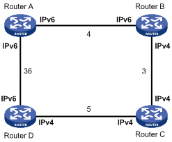
As shown in Figure 1, the numbers refer to the link costs. Router A, Router B, and Router D support both IPv4 and IPv6. Router C supports only IPv4 and cannot forward IPv6 packets.
Enable IPv6 IS-IS MTR on Router A, Router B, Router C, and Router D to make them perform route calculation separately in IPv4 and IPv6 topologies. With this configuration, Router A does not forward IPv6 packets destined to Router D through Router B, avoiding packet loss.
For more information about MTR and IS-IS MTR, see "Configuring MTR" and "Configuring IS-IS."
Configuration prerequisites
Before you configure IPv6 IS-IS MTR, configure basic IPv4 and IPv6 IS-IS functions, and establish IS-IS neighbors.
Configuration procedure
To enable IPv6 IS-IS MTR:
|
Step |
Command |
Remarks |
|
1. Enter system view. |
system-view |
N/A |
|
2. Enter IS-IS view. |
isis [ process-id ] [ vpn-instance vpn-instance-name ] |
N/A |
|
3. Specify an IS-IS cost style. |
cost-style { narrow | wide | wide-compatible | { compatible | narrow-compatible } [ relax-spf-limit ] } |
By default, the IS-IS cost style is narrow. |
|
4. Enable IPv6 for the IS-IS process |
ipv6 enable |
By default, IPv6 is disabled for an IS-IS process. |
|
5. Enter IPv6 address family view. |
address-family ipv6 [ unicast ] |
N/A |
|
6. Enable IPv6 IS-IS MTR. |
multi-topology |
By default, IPv6 IS-IS MTR is disabled. |
Displaying and maintaining IPv6 IS-IS
Execute display commands in any view. For other display and reset commands, see "Configuring IS-IS."
|
Command |
|
|
Display information about routes redistributed by IPv6 IS-IS. |
display isis redistribute ipv6 [ ipv6-address mask-length ] [ level-1 | level-2 ] [ process-id ] |
|
Display IPv6 IS-IS routing information. |
display isis route ipv6 [ ipv6-address ] [ [ level-1 | level-2 ] | verbose ] * [ process-id ] |
|
Display IPv6 IS-IS topology information. |
display isis spf-tree ipv6 [ [ level-1 | level-2 ] | verbose ] * [ process-id ] |
IPv6 IS-IS configuration examples
IPv6 IS-IS basic configuration example
Network requirements
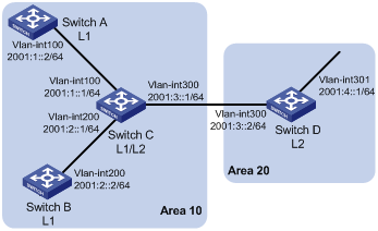
As shown in Figure 2, Switch A, Switch B, Switch C, and Switch D, all enabled with IPv6, reside in the same AS. Configure IPv6 IS-IS on the switches so that they can reach each other.
Switch A and Switch B are Level-1 switches, Switch D is a Level-2 switch, and Switch C is a Level-1-2 switch.
Configuration procedure
1. Configure IPv6 addresses for interfaces. (Details not shown.)
2. Configure IPv6 IS-IS:
# Configure Switch A.
<SwitchA> system-view
[SwitchA] isis 1
[SwitchA-isis-1] is-level level-1
[SwitchA-isis-1] network-entity 10.0000.0000.0001.00
[SwitchA-isis-1] ipv6 enable
[SwitchA-isis-1] quit
[SwitchA] interface vlan-interface 100
[SwitchA-Vlan-interface100] isis ipv6 enable 1
[SwitchA-Vlan-interface100] quit
# Configure Switch B.
<SwitchB> system-view
[SwitchB] isis 1
[SwitchB-isis-1] is-level level-1
[SwitchB-isis-1] network-entity 10.0000.0000.0002.00
[SwitchB-isis-1] ipv6 enable
[SwitchB-isis-1] quit
[SwitchB] interface vlan-interface 200
[SwitchB-Vlan-interface200] isis ipv6 enable 1
[SwitchB-Vlan-interface200] quit
# Configure Switch C.
<SwitchC> system-view
[SwitchC] isis 1
[SwitchC-isis-1] network-entity 10.0000.0000.0003.00
[SwitchC-isis-1] ipv6 enable
[SwitchC-isis-1] quit
[SwitchC] interface vlan-interface 100
[SwitchC-Vlan-interface100] isis ipv6 enable 1
[SwitchC-Vlan-interface100] quit
[SwitchC] interface vlan-interface 200
[SwitchC-Vlan-interface200] isis ipv6 enable 1
[SwitchC-Vlan-interface200] quit
[SwitchC] interface vlan-interface 300
[SwitchC-Vlan-interface300] isis ipv6 enable 1
[SwitchC-Vlan-interface300] quit
# Configure Switch D.
<SwitchD> system-view
[SwitchD] isis 1
[SwitchD-isis-1] is-level level-2
[SwitchD-isis-1] network-entity 20.0000.0000.0004.00
[SwitchD-isis-1] ipv6 enable
[SwitchD-isis-1] quit
[SwitchD] interface vlan-interface 300
[SwitchD-Vlan-interface300] isis ipv6 enable 1
[SwitchD-Vlan-interface300] quit
[SwitchD] interface vlan-interface 301
[SwitchD-Vlan-interface301] isis ipv6 enable 1
[SwitchD-Vlan-interface301] quit
Verifying the configuration
# Display the IPv6 IS-IS routing table on Switch A.
[SwitchA] display isis route ipv6
Route information for IS-IS(1)
------------------------------
Level-1 IPv6 Forwarding Table
-----------------------------
Destination : :: PrefixLen: 0
Flag : R/-/- Cost : 10
Next Hop : FE80::200:FF:FE0F:4 Interface: Vlan100
Destination : 2001:1:: PrefixLen: 64
Flag : D/L/- Cost : 10
Next Hop : Direct Interface: Vlan100
Destination : 2001:2:: PrefixLen: 64
Flag : R/-/- Cost : 20
Next Hop : FE80::200:FF:FE0F:4 Interface: Vlan100
Destination : 2001:3:: PrefixLen: 64
Flag : R/-/- Cost : 20
Next Hop : FE80::200:FF:FE0F:4 Interface: Vlan100
Flags: D-Direct, R-Added to Rib, L-Advertised in LSPs, U-Up/Down Bit Set
# Display the IPv6 IS-IS routing table on Switch B.
[SwitchB] display isis route ipv6
Route information for IS-IS(1)
------------------------------
Level-1 IPv6 Forwarding Table
-----------------------------
Destination : :: PrefixLen: 0
Flag : R/-/- Cost : 10
Next Hop : FE80::200:FF:FE0F:4 Interface: Vlan200
Destination : 2001:1:: PrefixLen: 64
Flag : D/L/- Cost : 10
Next Hop : FE80::200:FF:FE0F:4 Interface: Vlan200
Destination : 2001:2:: PrefixLen: 64
Flag : R/-/- Cost : 20
Next Hop : Direct Interface: Vlan200
Destination : 2001:3:: PrefixLen: 64
Flag : R/-/- Cost : 20
Next Hop : FE80::200:FF:FE0F:4 Interface: Vlan200
Flags: D-Direct, R-Added to Rib, L-Advertised in LSPs, U-Up/Down Bit Set
# Display the IPv6 IS-IS routing table on Switch C.
[SwitchC] display isis route ipv6
Route information for IS-IS(1)
------------------------------
Level-1 IPv6 Forwarding Table
-----------------------------
Destination : 2001:1:: PrefixLen: 64
Flag : D/L/- Cost : 10
Next Hop : Direct Interface: Vlan100
Destination : 2001:2:: PrefixLen: 64
Flag : D/L/- Cost : 10
Next Hop : Direct Interface: Vlan200
Destination : 2001:3:: PrefixLen: 64
Flag : D/L/- Cost : 10
Next Hop : Direct Interface: Vlan300
Flags: D-Direct, R-Added to Rib, L-Advertised in LSPs, U-Up/Down Bit Set
Level-2 IPv6 Forwarding Table
-----------------------------
Destination : 2001:1:: PrefixLen: 64
Flag : D/L/- Cost : 10
Next Hop : Direct Interface: Vlan100
Destination : 2001:2:: PrefixLen: 64
Flag : D/L/- Cost : 10
Next Hop : Direct Interface: Vlan200
Destination : 2001:3:: PrefixLen: 64
Flag : D/L/- Cost : 10
Next Hop : Direct Interface: Vlan300
Destination : 2001:4::1 PrefixLen: 128
Flag : R/-/- Cost : 10
Next Hop : FE80::20F:E2FF:FE3E:FA3D Interface: Vlan300
Flags: D-Direct, R-Added to Rib, L-Advertised in LSPs, U-Up/Down Bit Set
# Display the IPv6 IS-IS routing table on Switch D.
[SwitchD] display isis route ipv6
Route information for IS-IS(1)
------------------------------
Level-2 IPv6 Forwarding Table
-----------------------------
Destination : 2001:1:: PrefixLen: 64
Flag : R/-/- Cost : 20
Next Hop : FE80::200:FF:FE0F:4 Interface: Vlan300
Destination : 2001:2:: PrefixLen: 64
Flag : R/-/- Cost : 20
Next Hop : FE80::200:FF:FE0F:4 Interface: Vlan300
Destination : 2001:3:: PrefixLen: 64
Flag : D/L/- Cost : 10
Next Hop : Direct Interface: Vlan300
Destination : 2001:4::1 PrefixLen: 128
Flag : D/L/- Cost : 0
Next Hop : Direct Interface: Loop1
Flags: D-Direct, R-Added to Rib, L-Advertised in LSPs, U-Up/Down Bit Set
BFD for IPv6 IS-IS configuration example
Network requirements
As shown in Figure 3:
· Configure IPv6 IS-IS on Switch A and Switch B so that they can reach other.
· Enable BFD on VLAN-interface 10 of Switch A and Switch B.
After the link between Switch B and the Layer-2 switch fails, BFD can quickly detect the failure and notify IPv6 IS-IS of the failure. Then Switch A and Switch B communicate through Switch C.
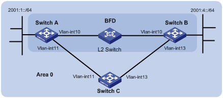
Table 1 Interface and IP address assignment
|
Device |
Interface |
IPv6 address |
|
Switch A |
Vlan-int10 |
2001::1/64 |
|
Switch A |
Vlan-int11 |
2001:2::1/64 |
|
Switch B |
Vlan-int10 |
2001::2/64 |
|
Switch B |
Vlan-int13 |
2001:3::2/64 |
|
Switch C |
Vlan-int11 |
2001:2::2/64 |
|
Switch C |
Vlan-int13 |
2001:3::1/64 |
Configuration procedure
1. Configure IPv6 addresses for interfaces. (Details not shown.)
2. Configure IPv6 IS-IS:
# Configure Switch A.
<SwitchA> system-view
[SwitchA] isis 1
[SwitchA-isis-1] is-level level-1
[SwitchA-isis-1] network-entity 10.0000.0000.0001.00
[SwitchA-isis-1] ipv6 enable
[SwitchA-isis-1] quit
[SwitchA] interface vlan-interface 10
[SwitchA-Vlan-interface10] isis ipv6 enable 1
[SwitchA-Vlan-interface10] quit
[SwitchA] interface vlan-interface 11
[SwitchA-Vlan-interface11] isis ipv6 enable 1
[SwitchA-Vlan-interface11] quit
# Configure Switch B.
<SwitchB> system-view
[SwitchB] isis 1
[SwitchB-isis-1] is-level level-1
[SwitchB-isis-1] network-entity 10.0000.0000.0002.00
[SwitchB-isis-1] ipv6 enable
[SwitchB-isis-1] quit
[SwitchB] interface vlan-interface 10
[SwitchB-Vlan-interface10] isis ipv6 enable 1
[SwitchB-Vlan-interface10] quit
[SwitchB] interface vlan-interface 13
[SwitchB-Vlan-interface13] isis ipv6 enable 1
[SwitchB-Vlan-interface13] quit
# Configure Switch C.
<SwitchC> system-view
[SwitchC] isis 1
[SwitchC-isis-1] network-entity 10.0000.0000.0003.00
[SwitchC-isis-1] ipv6 enable
[SwitchC-isis-1] quit
[SwitchC] interface vlan-interface 11
[SwitchC-Vlan-interface11] isis ipv6 enable 1
[SwitchC-Vlan-interface11] quit
[SwitchC] interface vlan-interface 13
[SwitchC-Vlan-interface13] isis ipv6 enable 1
[SwitchC-Vlan-interface13] quit
3. Configure BFD functions:
# Enable BFD and configure BFD parameters on Switch A.
[SwitchA] bfd session init-mode active
[SwitchA] interface vlan-interface 10
[SwitchA-Vlan-interface10] isis ipv6 bfd enable
[SwitchA-Vlan-interface10] bfd min-transmit-interval 500
[SwitchA-Vlan-interface10] bfd min-receive-interval 500
[SwitchA-Vlan-interface10] bfd detect-multiplier 7
[SwitchA-Vlan-interface10] return
# Enable BFD and configure BFD parameters on Switch B.
[SwitchB] bfd session init-mode active
[SwitchB] interface vlan-interface 10
[SwitchB-Vlan-interface10] isis ipv6 bfd enable
[SwitchB-Vlan-interface10] bfd min-transmit-interval 500
[SwitchB-Vlan-interface10] bfd min-receive-interval 500
[SwitchB-Vlan-interface10] bfd detect-multiplier 6
Verifying the configuration
# Display BFD session information on Switch A.
<SwitchA> display bfd session
Total Session Num: 1 Up Session Num: 1 Init Mode: Active
IPv6 Session Working Under Ctrl Mode:
Local Discr: 1441 Remote Discr: 1450
Source IP: FE80::20F:FF:FE00:1202 (link-local address of VLAN-interface 10 on Switch A)
Destination IP: FE80::20F:FF:FE00:1200 (link-local address of VLAN-interface 10 on Switch B)
Session State: Up Interface: Vlan10
Hold Time: 2319ms
# Display routes destined for 2001:4::0/64 on Switch A.
<SwitchA> display ipv6 routing-table 2001:4::0 64
Summary Count : 1
Destination: 2001:4::/64 Protocol : ISISv6
NextHop : FE80::20F:FF:FE00:1200 Preference: 15
Interface : Vlan10 Cost : 10
The output shows that Switch A and Switch B communicate through VLAN-interface 10. Then the link over VLAN-interface 10 fails.
# Display routes destined for 2001:4::0/64 on Switch A.
<SwitchA> display ipv6 routing-table 2001:4::0 64
Summary Count : 1
Destination: 2001:4::/64 Protocol : ISISv6
NextHop : FE80::BAAF:67FF:FE27:DCD0 Preference: 15
Interface : Vlan11 Cost : 20
The output shows that Switch A and Switch B communicate through VLAN-interface 11.