- Table of Contents
-
- 05-Layer 3 - IP Services Configuration Guide
- 00-Preface
- 01-ARP configuration
- 02-IP addressing configuration
- 03-DHCP configuration
- 04-DNS configuration
- 05-IP forwarding basics configuration
- 06-Adjacency table configuration
- 07-IRDP configuration
- 08-IP performance optimization configuration
- 09-UDP Helper configuration
- 10-IPv6 basics configuration
- 11-DHCPv6 configuration
- 12-Tunneling configuration
- 13-GRE configuration
- Related Documents
-
| Title | Size | Download |
|---|---|---|
| 08-IP performance optimization configuration | 88.04 KB |
Contents
Setting TCP MSS for an interface
Configuring TCP path MTU discovery
Enabling sending ICMP error messages
Disabling forwarding ICMP fragments
Configuring rate limit for ICMP error messages
Specifying the source address for ICMP packets
Displaying and maintaining IP performance optimization
Optimizing IP performance
Enabling an interface to receive and forward directed broadcasts destined for the directly connected network
A directed broadcast packet is destined for all hosts on a specific network. In the destination IP address of the directed broadcast, the network ID identifies the target network, and the host ID is made up of all ones.
If an interface is allowed to forward directed broadcasts destined for the directly connected network, hackers can exploit this vulnerability to attack the target network. In some scenarios, however, an interface must receive and send such directed broadcast packets to support UDP helper and Wake on LAN.
This task enables an interface to accept directed broadcast packets that are destined for and received from the directly connected network to support UDP helper. UDP helper converts the directed broadcasts to unicasts and forwards them to a specific server.
The task also enables the interface to forward directed broadcast packets that are destined for the directly connected network and are received from another subnet to support Wake on LAN. Wake on LAN sends the directed broadcasts to wake up the hosts on the target network.
Configuration procedure
To enable an interface to receive and forward directed broadcasts destined to the directly connected network:
|
Step |
Command |
Remarks |
|
1. Enter system view. |
system-view |
N/A |
|
2. Enter interface view. |
interface interface-type interface-number |
N/A |
|
3. Enable the interface to receive and forward directed broadcasts destined for the directly connected network. |
ip forward-broadcast |
By default, an interface cannot forward directed broadcasts destined for the directly connected network but can receive directed broadcasts destined for the directly connected network. |
Configuration example
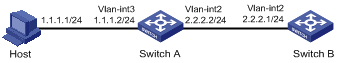
Network requirements
As shown in Figure 1, the default gateway of the host is the IP address 1.1.1.2/24 of VLAN-interface 3 of Switch A.
Switch B can receive directed broadcasts from the host to IP address 2.2.2.255.
Configuration procedure
1. Configure Switch A:
# Specify IP addresses for VLAN-interface 3 and VLAN-interface 2.
<SwitchA> system-view
[SwitchA] interface vlan-interface 3
[SwitchA-Vlan-interface3] ip address 1.1.1.2 24
[SwitchA-Vlan-interface3] quit
[SwitchA] interface vlan-interface 2
[SwitchA-Vlan-interface2] ip address 2.2.2.2 24
# Enable VLAN-interface 2 to forward directed broadcasts directed for the directly connected network.
[SwitchA-Vlan-interface2] ip forward-broadcast
# Configure a static route to the host.
<SwitchB> system-view
[SwitchB] ip route-static 1.1.1.1 24 2.2.2.2
# Specify an IP address for VLAN-interface 2.
[SwitchB] interface vlan-interface 2
[SwitchB-Vlan-interface2] ip address 2.2.2.1 24
# Enable VLAN-interface 2 to receive directed broadcasts destined for the directly connected network.
[SwitchB-Vlan-interface2] ip forward-broadcast
After the configurations are completed, if you ping the subnet-directed broadcast address 2.2.2.255 on the host, VLAN-interface 2 of Switch B can receive the ping packets. If you remove the ip forward-broadcast configuration on any switch, the interface cannot receive the ping packets.
Setting MTU for an interface
When a packet exceeds the MTU of the output interface, the device processes it in one of the following ways:
· If the packet disallows fragmentation, the device discards it.
· If the packet allows fragmentation, the device fragments it and forwards the fragments.
Fragmentation and reassembling consume system resources, so set an appropriate MTU for an interface based on the network environment to avoid fragmentation.
To set an MTU for an interface:
|
Step |
Command |
Remarks |
|
1. Enter system view. |
system-view |
N/A |
|
2. Enter interface view. |
interface interface-type interface-number |
N/A |
|
3. Set an MTU for the interface. |
ip mtu mtu-size |
By default, no MTU is set. |
Setting TCP MSS for an interface
The maximum segment size (MSS) option informs the receiver of the largest segment that the sender can accept. Each end announces its MSS during TCP connection establishment. If the size of a TCP segment is smaller than the MSS of the receiver, TCP sends the TCP segment without fragmentation. If not, it fragments the segment according to the receiver's MSS.
If you set a TCP MSS on an interface, the size of each TCP segment received or sent on the interface cannot exceed the MSS value.
This configuration takes effect only for TCP connections established after the configuration rather than the TCP connections that already exist.
This configuration is effective only for IP packets. If MPLS is enabled on the interface, do not set the TCP MSS on the interface.
To set a TCP MSS for the interface:
|
Step |
Command |
Remarks |
|
1. Enter system view. |
system-view |
N/A |
|
2. Enter interface view. |
interface interface-type interface-number |
N/A |
|
3. Set a TCP MSS for the interface. |
By default, no TCP MSS is set. |
Configuring TCP path MTU discovery
|
|
IMPORTANT: All devices on a TCP connection must be enabled to send ICMP error messages by using the ip unreachables enable command. |
TCP path MTU discovery (in RFC 1191) discovers the path MTU between the source and destination ends of a TCP connection. It works as follows:
1. A TCP source device sends a packet with the Don't Fragment (DF) bit set.
2. A router discards the packet that exceeds the MTU of the outgoing interface and returns an ICMP error message. The error message contains the MTU of the outgoing interface.
3. Upon receiving the ICMP message, the TCP source device calculates the current path MTU of the TCP connection.
4. The TCP source device sends subsequent TCP segments that each are smaller than the MSS (MSS = path MTU – IP header length – TCP header length).
If the TCP source device still receives ICMP error messages when the MSS is smaller than 32 bytes, the TCP source device will fragment packets.
An ICMP error message received from a router that does not support RFC 1191 has the MTU of the outgoing interface set to 0. Upon receiving the ICMP message, the TCP source device selects the path MTU smaller than the current path MTU from the MTU table as described in RFC 1191. Based on the selected path MTU, the TCP source device calculates the TCP MSS. The MTU table contains MTUs of 68, 296, 508, 1006, 1280, 1492, 2002, 4352, 8166, 17914, 32000, and 65535 bytes. Because the minimum TCP MSS specified by the system is 32 bytes, the actual minimum MTU is 72 bytes.
After you enable TCP path MTU discovery, all new TCP connections will detect the path MTU. The device uses the path MTU to calculate the MSS to avoid IP fragmentation.
The path MTU uses the following aging mechanism to make sure the source device can increase the path MTU when the minimum link MTU on the path increases:
· When the TCP source device receives an ICMP error message, it reduces the path MTU and starts an aging timer for the path MTU.
· After the aging timer expires, the source device uses a larger MSS in the MTU table, as described in RFC 1191.
· If no ICMP error message is received within two minutes, the source device increases the MSS again until the MSS negotiated during TCP three-way handshake is reached.
To enable TCP path MTU discovery:
|
Step |
Command |
Remarks |
|
1. Enter system view. |
system-view |
N/A |
|
2. Enable TCP path MTU discovery. |
tcp path-mtu-discovery [ aging age-time | no-aging ] |
The default setting is disabled. |
Enabling TCP SYN Cookie
A TCP connection is established through a three-way handshake:
1. The sender sends a SYN packet to the server.
2. The server receives the SYN packet, establishes a TCP semi-connection in SYN_RECEIVED state, and replies with a SYN ACK packet to the sender.
3. The sender receives the SYN ACK packet and replies with an ACK packet. A TCP connection is established.
An attacker can exploit this mechanism to mount SYN Flood attacks. The attacker sends a large number of SYN packets, but does not respond to the SYN ACK packets from the server. As a result, the server establishes a large number of TCP semi-connections and can no longer handle normal services.
SYN Cookie can protect the server from SYN Flood attacks. When the server receives a SYN packet, it responds with a SYN ACK packet without establishing a TCP semi-connection. The server establishes a TCP connection and enters ESTABLISHED state only when it receives an ACK packet from the client.
To enable TCP SYN Cookie:
|
Step |
Command |
Remarks |
|
1. Enter system view. |
system-view |
N/A |
|
2. Enable SYN Cookie. |
tcp syn-cookie enable |
The default setting is disabled. |
Setting the TCP buffer size
|
Step |
Command |
Remarks |
|
1. Enter system view. |
system-view |
N/A |
|
2. Set the size of TCP receive/send buffer. |
tcp window window-size |
The default buffer size is 64 KB. |
Setting TCP timers
You can set the following TCP timers:
· SYN wait timer—TCP starts the SYN wait timer after sending a SYN packet. If no response packet is received within the SYN wait timer interval, TCP fails to establish the connection.
· FIN wait timer—TCP starts the FIN wait timer when the state changes to FIN_WAIT_2. If no FIN packet is received within the timer interval, TCP terminates the connection. If a FIN packet is received, TCP changes the connection state to TIME_WAIT. If a non-FIN packet is received, TCP restarts the timer, and tears down the connection when the timer expires.
To set TCP timers:
|
Step |
Command |
Remarks |
|
1. Enter system view. |
system-view |
N/A |
|
2. Set TCP timers. |
· Set the TCP SYN wait
timer: · Set the TCP FIN wait
timer: |
By default: · The TCP SYN wait timer is 75 seconds. · The TCP FIN wait timer is 675 seconds. |
Enabling sending ICMP error messages
Perform this task to enable sending ICMP error messages, including redirect, time exceeded, and destination unreachable messages.
· ICMP redirect messages
A host that has only one default route sends all packets to the default gateway. The default gateway sends an ICMP redirect message to inform the host of a correct next hop by following these rules:
¡ The receiving and sending interfaces are the same.
¡ The selected route is not created or modified by any ICMP redirect messages.
¡ The selected route is not destined for 0.0.0.0.
¡ There is no source route option in the received packet.
ICMP redirect messages simplify host management and enable hosts to gradually optimize their routing table.
|
|
NOTE: Layer 3 Ethernet interfaces and Layer 3 aggregate Ethernet interfaces do not support sending ICMP redirect messages. |
· ICMP time exceeded messages
A device sends ICMP time exceeded messages by following these rules:
¡ The device sends the source an ICMP TTL exceeded in transit message when the following conditions are met:
- The received packet is not destined for the device.
- The TTL field of the packet is 1.
¡ When the device receives the first fragment of an IP datagram destined for it, it starts a timer. If the timer expires before all the fragments of the datagram are received, the device sends an ICMP fragment reassembly time exceeded message to the source.
· ICMP destination unreachable messages
A device sends ICMP destination unreachable messages by following these rules:
¡ The device sends the source an ICMP network unreachable message when the following conditions are met:
- The packet does not match any route.
- No default route exists in the routing table.
¡ The device sends the source an ICMP protocol unreachable message when the following conditions are met:
- The packet is destined for the device.
- The transport layer protocol of the packet is not supported by the device.
|
|
NOTE: If a DHCP enabled device receives an ICMP echo reply without sending any ICMP echo requests, the device does not send any ICMP protocol unreachable messages to the source. For more information about DHCP, see Layer 3—IP Services Configuration Guide. |
¡ The device sends the source an ICMP port unreachable message when the following conditions are met:
- The UDP packet is destined for the device.
- The packet's port number does not match the corresponding process.
¡ The device sends the source an ICMP source route failed message when the following conditions are met:
- The source uses Strict Source Routing to send packets.
- The intermediate device finds that the next hop specified by the source is not directly connected.
¡ The device sends the source an ICMP fragmentation needed and DF set message when the following conditions are met:
- The MTU of the sending interface is smaller than the packet.
- The packet has DF set.
To enable sending ICMP error messages:
|
Step |
Command |
Remarks |
|
1. Enter system view. |
system-view |
N/A |
|
2. Enable sending ICMP error messages. |
· Enable sending ICMP redirect messages: · Enable sending ICMP time exceeded messages: · Enable sending ICMP destination
unreachable messages: |
The default settings are disabled. |
Sending ICMP error messages facilitates network management, but sending excessive ICMP messages increases network traffic. The device performance degrades if it receives a lot of malicious ICMP messages that cause it to respond with ICMP error messages.
To prevent such problems, you can disable the device from sending ICMP error messages. A device that is disabled from sending ICMP time exceeded messages does not send ICMP TTL exceeded in transit messages. However, it can still send ICMP fragment reassembly time exceeded messages.
Disabling forwarding ICMP fragments
Disabling forwarding ICMP fragments can protect your device from ICMP fragments attacks.
To disable forwarding ICMP fragments:
|
Step |
Command |
Remarks |
|
1. Enter system view. |
system-view |
N/A |
|
2. Disable forwarding ICMP fragments. |
ip icmp fragment discarding |
By default, forwarding ICMP fragments is enabled. |
Configuring rate limit for ICMP error messages
To avoid sending excessive ICMP error messages within a short period that might cause network congestion, you can limit the rate at which ICMP error messages are sent. A token bucket algorithm is used with one token representing one ICMP error message.
A token is placed in the bucket at intervals until the maximum number of tokens that the bucket can hold is reached.
A token is removed from the bucket when an ICMP error message is sent. When the bucket is empty, ICMP error messages are not sent until a new token is placed in the bucket.
To configure rate limit for ICMP error messages:
|
Step |
Command |
Remarks |
|
1. Enter system view. |
system-view |
N/A |
|
2. Set the bucket size and the interval for tokens to arrive in the bucket for ICMP error messages. |
ip icmp error-interval milliseconds [ bucketsize ] |
By default, the bucket allows a maximum of 10 tokens. A token is placed in the bucket at an interval of 100 milliseconds. To disable the ICMP rate limit, set the interval to 0 milliseconds. |
Specifying the source address for ICMP packets
Perform this task to specify the source IP address for outgoing ping echo request and ICMP error messages. As a best practice, specify the IP address of the loopback interface as the source IP address. This feature helps users to locate the sending device easily.
If you specify an IP address in the ping command, ping echo requests use the specified address as the source IP address rather than the IP address specified by the ip icmp source command.
To specify the source IP address for ICMP packets:
|
Step |
Command |
Remarks |
|
1. Enter system view. |
system-view |
N/A |
|
2. Specify the source address for outgoing ICMP packets. |
ip icmp source [ vpn-instance vpn-instance-name ] ip-address |
By default, the device uses the IP address of the sending interface as the source IP address for outgoing ICMP packets. |
Displaying and maintaining IP performance optimization
Execute display commands in any view and reset commands in user view.
|
Task |
Command |
|
Display brief information about RawIP connections (in standalone mode). |
display rawip [ slot slot-number ] |
|
Display brief information about RawIP connections (in IRF mode). |
display rawip [ chassis chassis-number slot slot-number ] |
|
Display detailed information about RawIP connections (in standalone mode). |
display rawip verbose [ slot slot-number [ pcb pcb-index ] ] |
|
Display detailed information about RawIP connections (in IRF mode). |
display rawip verbose [ chassis chassis-number slot slot-number [ pcb pcb-index ] ] |
|
Display brief information about TCP connections (in standalone mode). |
display tcp [ slot slot-number ] |
|
Display brief information about TCP connections (in IRF mode). |
display tcp [ chassis chassis-number slot slot-number ] |
|
Display detailed information about TCP connections (in standalone mode). |
display tcp verbose [ slot slot-number [ pcb pcb-index ] ] |
|
Display detailed information about TCP connections (in IRF mode). |
display tcp verbose [ chassis chassis-number slot slot-number [ pcb pcb-index ] ] |
|
Display brief information about UDP connections (in standalone mode). |
display udp [ slot slot-number ] |
|
Display brief information about UDP connections (in IRF mode). |
display udp [ chassis chassis-number slot slot-number ] |
|
Display detailed information about UDP connections (in standalone mode). |
display udp verbose [ slot slot-number [ pcb pcb-index ] ] |
|
Display detailed information about UDP connections (in IRF mode). |
display udp verbose [ chassis chassis-number slot slot-number [ pcb pcb-index ] ] |
|
Display IP packet statistics (in standalone mode). |
display ip statistics [ slot slot-number ] |
|
Display IP packet statistics (in IRF mode). |
display ip statistics [ chassis chassis-number slot slot-number ] |
|
Display TCP traffic statistics (in standalone mode). |
display tcp statistics [ slot slot-number ] |
|
Display TCP traffic statistics (in IRF mode). |
display tcp statistics [ chassis chassis-number slot slot-number ] |
|
Display UDP traffic statistics (in standalone mode). |
display udp statistics [ slot slot-number ] |
|
Display UDP traffic statistics (in IRF mode). |
display udp statistics [ chassis chassis-number slot slot-number ] |
|
Display ICMP statistics (in standalone mode). |
display icmp statistics [ slot slot-number ] |
|
Display ICMP statistics (in IRF mode). |
display icmp statistics [ chassis chassis-number slot slot-number ] |
|
Clear IP packet statistics (in standalone mode). |
reset ip statistics [ slot slot-number ] |
|
Clear IP packet statistics (in IRF mode). |
reset ip statistics [ chassis chassis-number slot slot-number ] |
|
Clear TCP traffic statistics. |
reset tcp statistics |
|
Clear UDP traffic statistics. |
reset udp statistics |