- Table of Contents
- Related Documents
-
| Title | Size | Download |
|---|---|---|
| 08-MPLS L2VPN configuration | 210.34 KB |
Contents
Remote connection establishment
Configuration restrictions and guidelines
MPLS L2VPN configuration task list
Configuring a Layer 3 interface
Configuring an Ethernet service instance on a Layer 2 Ethernet interface
Binding an AC to a cross-connect
Binding a Layer 3 interface to a cross-connect
Binding an Ethernet service instance to a cross-connect
Displaying and maintaining MPLS L2VPN
LDP PW configuration example (flexible mode)
Overview
MPLS L2VPN is an implementation of Pseudo Wire Emulation Edge-to-Edge (PWE3). It offers Layer 2 VPN services over an MPLS or IP backbone. MPLS L2VPN can transparently transmit Layer 2 data for different data link layer protocols, including Ethernet, VLAN, ATM, FR, and PPP.
From a user's perspective, the MPLS or IP backbone is a Layer 2 switched network. For example, when two Ethernet networks are connected through MPLS L2VPN over an MPLS backbone, Ethernet users think that they are connected directly through an Ethernet.
Basic concepts of MPLS L2VPN
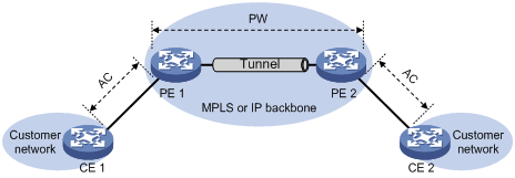
· Customer edge—A CE is a customer device directly connected to the service provider network.
· Provider edge—A PE is a service provider device connected to one or more CEs. It provides VPN access by mapping and forwarding packets between user networks and public tunnels.
· Attachment circuit—An AC is a link between a CE and a PE, such as an FR DLCI, ATM VPI/VCI, Ethernet interface, VLAN, or PPP connection.
· Pseudowire—A PW is a virtual bidirectional connection between two PEs. An MPLS PW comprises a pair of LSPs in opposite directions.
· Public tunnel—A public tunnel is a connection that carries one or more PWs across the MPLS or IP backbone. It can be an LSP tunnel.
· Cross-connect—A cross-connect concatenates two physical or virtual circuits such as ACs and PWs. It switches packets between the two physical or virtual circuits. Cross-connects include AC to AC cross-connect, AC to PW cross-connect, and PW to PW cross-connect.
MPLS L2VPN network models
MPLS L2VPN network models include the remote connection and local connection models.
Remote connection model
As shown in Figure 1, this model connects two CEs through a PW on an MPLS or IP backbone.
Figure 1 Remote connection model
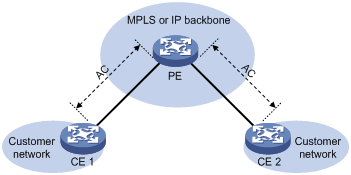
Local connection model
As shown in Figure 2, this model connects two CEs to the same PE so the CEs can communicate through the PE. The switch does not support the local connection model.
Figure 2 Local connection model
Remote connection establishment
To set up a remote MPLS L2VPN connection:
1. Set up a public tunnel to carry one or more PWs between PEs:
The public tunnel can only be an LSP tunnel.
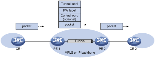
If a PW is established over an LSP tunnel, packets on the PW have two labels. The outer label is the public LSP tunnel label that MPLS uses to forward the packet within the MPLS network. The inner label is the PW label that the peer PE uses to forward the packet to the destination CE.
2. Set up a PW to connect customer networks:
A PW can be established statically or dynamically through LDP.
To establish a static PW, configure the peer PE address, and the incoming and outgoing PW labels for the PW on the two PEs. Static PWs consume a small amount of resources but have complex configurations.
To establish an LDP PW, configure LDP and specify the peer PE address on the two PEs. LDP defines a new FEC type named PW ID FEC for PEs to exchange PW-label bindings. The new FEC type uses a PW ID and a PW type to identify a PW. The PW ID is the ID of the PW between PEs. The PW type specifies the encapsulation type for data transmitted over the PW, such as ATM, FR, Ethernet, or VLAN. PEs advertise the PW label and PW ID FEC in label mapping messages to create a PW. Dynamic PWs have simple configurations but consume more resources than static PWs.
3. Set up an AC between a PE and a CE:
Set up an AC by configuring a link layer connection (such as a PPP connection) between a PE and a CE.
An AC can be one of the following types:
¡ Layer 3 physical interface—Transparently forwards received packets over the bound PW. The Layer 3 physical interface can be an Ethernet interface, or an ATM interface.
¡ Layer 3 subinterface—Forwards packets received from the corresponding link (VLAN, ATM VPC, ATM VCC, or FR DLCI ) to the bound PW. In this mode, VLANs are unique on a per interface basis rather than on a global basis.
¡ VLAN interface—Forwards packets received from the VLAN to the bound PW. In this mode, VLANs are globally unique.
¡ Ethernet service instance on a Layer 2 Ethernet interface—Forwards packets that are received on the Layer 2 Ethernet interface and meet the match criteria of the Ethernet service instance to the bound PW. If the match criterion is VLAN ID, the VLAN is unique on a per interface basis rather than on a global basis.
|
|
NOTE: When VLANs are globally unique, packets with the same VLAN ID are forwarded over the PW bound with that VLAN ID regardless of the receiving interfaces. If VLANs are unique on a per interface basis, packets with the same VLAN ID from different interfaces can be forwarded over different PWs. |
4. Bind the AC to the PW:
Bind the Layer 3 physical interface, Layer 3 subinterface, VLAN interface, or Ethernet service instance to the PW, so the PE forwards packets between the AC and the PW.
Ethernet over MPLS
Ethernet over MPLS supports the following modes:
· Port mode—A Layer 3 Ethernet interface is bound to a PW. Packets received from the Layer 3 Ethernet interface are forwarded through the bound PW. The default data encapsulation type for port mode is Ethernet.
Figure 3 Packet encapsulation in port mode
· VLAN mode—A Layer 3 Ethernet subinterface or VLAN interface is bound to a PW. Packets received from the VLAN are forwarded through the bound PW. The peer PE can modify the VLAN tag as needed. The default data encapsulation type for VLAN mode is VLAN.
· Flexible mode—An Ethernet service instance on a Layer 2 Ethernet interface is bound to a PW. Packets that are received from the Layer 2 Ethernet interface and meet the match criteria of the Ethernet service instance are forwarded to the bound PW. You can configure flexible match criteria for the Ethernet service instance. For example, configure the Ethernet service instance to match all packets, tagged packets, or untagged packets. The default data encapsulation type for flexible mode is VLAN. Flexible mode can also implement the port and VLAN modes through match criteria configuration.
VCCV
Virtual Circuit Connectivity Verification (VCCV) is an OAM function for L2VPN. It verifies the connectivity of PWs on the data plane. VCCV includes two modes:
· Manual mode—Use the ping mpls pw command to manually test the connectivity of a PW.
· Auto mode—Configure BFD or Raw BFD to automatically test the connectivity of a PW.
For more information about VCCV, see "Configuring MPLS OAM."
Configuration restrictions and guidelines
Follow these restrictions and guidelines when you configure MPLS L2VPN:
· The switch does not support MPLS L2VPN when the system is operating in standard mode. For more information about system operating modes, see Fundamentals Configuration Guide.
· After the mpls label advertise command is executed, the forwarding entries for a cross-connect group in the MPLS L2VPN network are not automatically refreshed. To ensure correct forwarding, disable the cross-connect group, and then enable it.
MPLS L2VPN configuration task list
To establish an MPLS L2VPN, you must perform the following tasks:
· Configure an IGP to ensure IP connectivity within the backbone.
· Configure basic MPLS or LDP to set up public tunnels across the backbone.
· Configure MPLS L2VPN on the PEs, including setting up PWs, and binding ACs to PWs.
This chapter only describes MPLS L2VPN configurations on the PEs.
MPLS L2VPN configurations vary by the following scenario:
· Remote connection—To create a remote connection, configure an AC, configure a PW in cross-connect view, and bind the AC with the PW in cross-connect view.
· Local connection—To create a local connection, configure two ACs and bind the two ACs in cross-connect view.
To configure MPLS L2VPN on a PE:
|
Tasks at a glance |
Remarks |
|
(Required.) Enabling L2VPN |
N/A |
|
(Required.) Configuring an AC: · Configuring a Layer 3 interface · Configuring an Ethernet service instance on a Layer 2 Ethernet interface |
Choose either task depending on the AC type. |
|
(Required.) Configuring a cross-connect |
N/A |
|
· (Optional.) Configuring a PW class · (Required.) Configuring an LDP PW |
N/A |
|
(Required.) Binding an AC to a cross-connect: |
Choose either task to bind an AC to a cross-connect. |
Enabling L2VPN
Before you enable L2VPN, perform the following tasks:
· Configure an LSR ID for the PE with the mpls lsr-id command.
· Enable MPLS with the mpls enable command on the backbone interface of the PE.
For more information about these commands, see MPLS Command Reference.
To enable L2VPN:
|
Step |
Command |
Remarks |
|
1. Enter system view. |
system-view |
N/A |
|
2. Enable L2VPN. |
l2vpn enable |
By default, L2VPN is disabled. |
Configuring an AC
Configuring a Layer 3 interface
Configure the Layer 3 interface connected to the CE to create a Layer 2 link between the PE and CE.
The Layer 3 interface type determines the access mode of the AC. On a Layer 3 Ethernet interface or Layer 3 Ethernet subinterface, you can use the access-mode keyword of the ac interface command to specify the access mode as Ethernet or VLAN. By default, the default access mode is Ethernet on a Layer 3 Ethernet interface and is VLAN on a Layer 3 Ethernet subinterface.
For more information about Ethernet interfaces, see Interface Configuration Guide.
Configuring an Ethernet service instance on a Layer 2 Ethernet interface
When the PE connects to a CE through a Layer 2 Ethernet interface, you can configure an Ethernet service instance on the Layer 2 Ethernet interface to match specific packets from the AC.
To configure an Ethernet service instance:
|
Step |
Command |
Remarks |
|
1. Enter system view. |
system-view |
N/A |
|
1. Enter Layer 2 Ethernet interface view. |
interface interface-type interface-number |
N/A |
|
2. Create an Ethernet service instance and enter Ethernet service instance view. |
service-instance instance-id |
By default, no Ethernet service instance is created. |
|
3. Configure match criteria for the Ethernet service instance. |
encapsulation s-vid vlan-id [ only-tagged ] |
By default, no match criteria are configured for the Ethernet service instance. |
Configuring a cross-connect
|
Step |
Command |
Remarks |
|
1. Enter system view. |
system-view |
N/A |
|
2. Create a cross-connect group and enter cross-connect group view. |
xconnect-group group-name |
By default, no cross-connect group is created. |
|
3. (Optional.) Configure a description for the cross-connect group. |
description text |
By default, no description is configured for the cross-connect group. |
|
4. (Optional.) Enable the cross-connect group. |
undo shutdown |
By default, the cross-connect group is enabled. |
|
5. Create a cross-connect and enter cross-connect view. |
connection connection-name |
By default, no cross-connect is created. |
|
6. Configure an MTU for the PW. |
mtu mtu |
The default MTU is 1500 bytes. The two PEs on an LDP PW must have the same MTU configured for the PW. Otherwise, the PW cannot go up. |
Configuring a PW
Configuring a PW class
You can configure PW attributes such as the PW type and enable control word in a PW class. PWs with the same attributes can reference the same PW class.
To configure a PW class:
|
Step |
Command |
Remarks |
|
1. Enter system view. |
system-view |
N/A |
|
2. Create a PW class and enter PW class view. |
pw-class class-name |
By default, no PW class is created. |
|
3. (Optional.) Specify the PW type. |
pw-type { ethernet | vlan } |
By default, the PW type is VLAN. |
Configuring an LDP PW
Before you configure an LDP PW, enable global and interface MPLS LDP on the PE. For information about MPLS LDP configuration, see "Configuring LDP."
To configure an LDP PW:
|
Step |
Command |
Remarks |
|
1. Enter system view. |
system-view |
N/A |
|
2. Enter cross-connect group view. |
xconnect-group group-name |
N/A |
|
3. Enter cross-connect view. |
connection connection-name |
N/A |
|
4. Configure an LDP PW and enter cross-connect PW view. |
peer ip-address pw-id pw-id [ pw-class class-name | tunnel-policy tunnel-policy-name ] * |
By default, no LDP PW is configured. If the specified peer PE is not directly connected, the local PE automatically sends a targeted hello to create an LDP session to the peer PE and then exchanges the PW ID FEC and PW label mapping with the peer. |
Binding an AC to a cross-connect
This task is mutually exclusive with Ethernet link aggregation. If a Layer 3 or Layer 2 Ethernet interface has been added to a link aggregation group, you cannot bind the Layer 3 interface or an Ethernet service instance on the Layer 2 interface to a cross-connect, and vice versa.
If the AC is a Layer 3 interface, bind the Layer 3 interface to the cross-connect.
If the AC is an Ethernet service instance on a Layer 2 Ethernet interface, bind the Ethernet service instance to the cross-connect.
Binding a Layer 3 interface to a cross-connect
After you bind a Layer 3 interface to a cross-connect, packets received from the interface are forwarded through the PW or another AC bound to the cross-connect.
To bind a Layer 3 interface to a cross-connect:
|
Step |
Command |
Remarks |
|
1. Enter system view. |
system-view |
N/A |
|
2. Enter cross-connect group view. |
xconnect-group group-name |
N/A |
|
3. Enter cross-connect view. |
connection connection-name |
N/A |
|
4. Bind the Layer 3 interface to the cross-connect. |
ac interface interface-type interface-number [ access-mode { ethernet | vlan } ] |
By default, no Layer 3 interface is bound to the cross-connect. |
Binding an Ethernet service instance to a cross-connect
After you bind an Ethernet service instance on a Layer 2 Ethernet interface to a cross-connect, packets received from the interface and those match the Ethernet service instance are forwarded to the bound PW or another AC. An Ethernet service instance can match all packets, tagged packets, or untagged packets.
To bind an Ethernet service instance to a cross-connect:
|
Step |
Command |
Remarks |
|
1. Enter system view. |
system-view |
N/A |
|
2. Enter cross-connect group view. |
xconnect-group group-name |
N/A |
|
3. Enter cross-connect view. |
connection connection-name |
N/A |
|
4. Bind the Ethernet service instance on the Layer 2 Ethernet interface to the cross-connect. |
ac interface interface-type interface-number service-instance instance-id [ access-mode { ethernet | vlan } ] |
By default, no Ethernet service instance is bound to the cross-connect. |
Displaying and maintaining MPLS L2VPN
Execute display commands in any view.
|
Task |
Command |
|
Display LDP PW label information. |
display l2vpn ldp [ peer ip-address [ pw-id pw-id ] | xconnect-group group-name ] [ verbose ] |
|
Display cross-connect forwarding information (in standalone mode). |
display l2vpn forwarding { ac | pw } [ xconnect-group group-name ] [ slot slot-number ] [ verbose ] |
|
Display cross-connect forwarding information (in IRF mode). |
display l2vpn forwarding { ac | pw } [ xconnect-group group-name ] [ chassis chassis-number slot slot-number ] [ verbose ] |
|
Display L2VPN information for the Layer 3 interface bound to a cross-connect. |
display l2vpn interface [ xconnect-group group-name | interface-type interface-number ] |
|
Display L2VPN PW information. |
display l2vpn pw [ xconnect-group group-name ] [ protocol { bgp | ldp | static } ] [ verbose ] |
|
Display PW class information. |
display l2vpn pw-class [ class-name ] |
|
Display Ethernet service instance information. |
display l2vpn service-instance [ interface interface-type interface-number [ service-instance instance-id ] ] [ verbose ] |
|
Display cross-connect group information. |
display l2vpn xconnect-group [ name group-name ] [ verbose ] |
|
Display BGP L2VPN peer group information. |
display bgp group l2vpn [ group-name group-name ] |
|
Display BGP L2VPN peer information. |
display bgp peer l2vpn [ ip-address mask-length | group-name group-name log-info | ip-address { log-info | verbose } | verbose ] |
For more information about the display bgp group l2vpn, display bgp peer l2vpn, and display bgp update-group l2vpn commands, see Layer 3—IP Routing Command Reference.
LDP PW configuration example (flexible mode)
By default, Ethernet, VLAN, and aggregate interfaces are shut down. You must use the undo shutdown command to bring them up. This example assumes that all these interfaces are already up.
Network requirements
Create an LDP PW between PE 1 and PE 2, and use flexible mode to match specific packets from each AC so CE 1 and CE 2 can communicate within VLAN 10 without consuming VLAN resources on PEs.
Figure 4 Network diagram
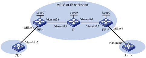
Table 1 Interface and IP address assignment
|
Device |
Interface |
IP address |
Device |
Interface |
IP address |
|
CE 1 |
Vlan-int10 |
100.1.1.1/24 |
P |
Loop0 |
192.4.4.4/32 |
|
PE 1 |
Loop0 |
192.2.2.2/32 |
|
Vlan-int23 |
23.1.1.2/24 |
|
|
Vlan-int23 |
23.1.1.1/24 |
|
Vlan-int26 |
26.2.2.2/24 |
|
CE 2 |
Vlan-int10 |
100.1.1.2/24 |
PE 2 |
Loop0 |
192.3.3.3/32 |
|
|
|
|
|
Vlan-int26 |
26.2.2.1/24 |
Configuration procedure
1. Configure VLANs and add ports to VLANs on each switch. (Details not shown.)
2. Configure CE 1.
<CE1> system-view
[CE1] interface vlan-interface 10
[CE1-Vlan-interface10] ip address 100.1.1.1 24
[CE1-Vlan-interface10] quit
3. Configure PE 1:
# Configure an LSR ID.
<PE1> system-view
[PE1] interface loopback 0
[PE1-LoopBack0] ip address 192.2.2.2 32
[PE1-LoopBack0] quit
[PE1] mpls lsr-id 192.2.2.2
# Enable L2VPN.
[PE1] l2vpn enable
# Enable global LDP.
[PE1] mpls ldp
[PE1-ldp] quit
# Configure VLAN-interface 23 (the interface connected to the P device), and enable LDP on the interface.
[PE1] interface vlan-interface 23
[PE1-Vlan-interface23] ip address 23.1.1.1 24
[PE1-Vlan-interface23] mpls enable
[PE1-Vlan-interface23] mpls ldp enable
[PE1-Vlan-interface23] quit
# Configure OSPF on PE 1 for LDP to create LSPs.
[PE1] ospf
[PE1-ospf-1] area 0
[PE1-ospf-1-area-0.0.0.0] network 23.1.1.1 0.0.0.255
[PE1-ospf-1-area-0.0.0.0] network 192.2.2.2 0.0.0.0
[PE1-ospf-1-area-0.0.0.0] quit
[PE1-ospf-1] quit
# Create an Ethernet service instance on GigabitEthernet 3/0/1 (the interface connected to CE 1).
[PE1] interface GigabitEthernet 3/0/1
[PE1-GigabitEthernet3/0/1] service-instance 1000
[PE1-GigabitEthernet3/0/1-srv1000] encapsulation s-vid 10
[PE1-GigabitEthernet3/0/1-srv1000] quit
[PE1-GigabitEthernet3/0/1] quit
# Create a cross-connect group named vpn1, and create a cross-connect named ldp in the group.
[PE1] xconnect-group vpn1
[PE1-xcg-vpn1] connection ldp
# Bind Ethernet service instance 1000 on GigabitEthernet 3/0/1 to the cross-connect.
[PE1-xcg-vpn1-ldp] ac interface GigabitEthernet 3/0/1 service-instance 1000
# Create an LDP PW for the cross-connect to bind the AC to the PW.
[PE1-xcg-vpn1-ldp] peer 192.3.3.3 pw-id 1000
[PE1-xcg-vpn1-ldp-192.3.3.3-1000] quit
[PE1-xcg-vpn1-ldp] quit
[PE1-xcg-vpn1] quit
4. Configure the P device:
# Configure an LSR ID.
<P> system-view
[P] interface loopback 0
[P-LoopBack0] ip address 192.4.4.4 32
[P-LoopBack0] quit
[P] mpls lsr-id 192.4.4.4
# Enable global LDP.
[P] mpls ldp
[P-ldp] quit
# Configure VLAN-interface 23 (the interface connected to PE 1), and enable LDP on the interface.
[P] interface vlan-interface 23
[P-Vlan-interface23] ip address 23.1.1.2 24
[P-Vlan-interface23] mpls enable
[P-Vlan-interface23] mpls ldp enable
[P-Vlan-interface23] quit
# Configure VLAN-interface 26 (the interface connected to PE 2), and enable LDP on the interface.
[P] interface vlan-interface 26
[P-Vlan-interface26] ip address 26.2.2.2 24
[P-Vlan-interface26] mpls enable
[P-Vlan-interface26] mpls ldp enable
[P-Vlan-interface26] quit
# Configure OSPF on the P device for LDP to create LSPs.
[P] ospf
[P-ospf-1] area 0
[P-ospf-1-area-0.0.0.0] network 23.1.1.2 0.0.0.255
[P-ospf-1-area-0.0.0.0] network 26.2.2.2 0.0.0.255
[P-ospf-1-area-0.0.0.0] network 192.4.4.4 0.0.0.0
[P-ospf-1-area-0.0.0.0] quit
[P-ospf-1] quit
5. Configure PE 2:
# Configure an LSR ID.
<PE2> system-view
[PE2] interface loopback 0
[PE2-LoopBack0] ip address 192.3.3.3 32
[PE2-LoopBack0] quit
[PE2] mpls lsr-id 192.3.3.3
# Enable L2VPN.
[PE2] l2vpn enable
# Enable global LDP.
[PE2] mpls ldp
[PE2-ldp] quit
# Configure VLAN-interface 26 (the interface connected to the P device), and enable LDP on the interface.
[PE2] interface vlan-interface 26
[PE2-Vlan-interface26] ip address 26.2.2.1 24
[PE2-Vlan-interface26] mpls enable
[PE2-Vlan-interface26] mpls ldp enable
[PE2-Vlan-interface26] quit
# Configure OSPF on PE 2 for LDP to create LSPs.
[PE2] ospf
[PE2-ospf-1] area 0
[PE2-ospf-1-area-0.0.0.0] network 192.3.3.3 0.0.0.0
[PE2-ospf-1-area-0.0.0.0] network 26.2.2.0 0.0.0.255
[PE2-ospf-1-area-0.0.0.0] quit
[PE2-ospf-1] quit
# Create an Ethernet service instance on GigabitEthernet 3/0/1 (the interface connected to CE 2).
[PE2] interface GigabitEthernet 3/0/1
[PE2-GigabitEthernet3/0/1] service-instance 1000
[PE2-GigabitEthernet3/0/1-srv1000] encapsulation s-vid 10
[PE2-GigabitEthernet3/0/1-srv1000] quit
[PE2-GigabitEthernet3/0/1] quit
# Create a cross-connect group named vpn1, create a cross-connect named ldp in the group, bind Ethernet service instance 1000 on GigabitEthernet 3/0/1 to the cross-connect, and create an LDP PW for the cross-connect to bind the AC to the PW.
[PE2] xconnect-group vpn1
[PE2-xcg-vpn1] connection ldp
[PE2-xcg-vpn1-ldp] ac interface GigabitEthernet 3/0/1 service-instance 1000
[PE2-xcg-vpn1-ldp] peer 192.2.2.2 pw-id 1000
[PE2-xcg-vpn1-ldp-192.2.2.2-1000] quit
[PE2-xcg-vpn1-ldp] quit
[PE2-xcg-vpn1] quit
6. Configure CE 2.
<CE2> system-view
[CE2] interface vlan-interface 10
[CE2-Vlan-interface10] ip address 100.1.1.2 24
[CE2-Vlan-interface10] quit
Verifying the configuration
# Display L2VPN PW information on PE 1. The output shows that an LDP PW has been established.
[PE1] display l2vpn pw
Flags: M - main, B - backup, H - hub link, S - spoke link, N - no split horizon
Total number of PWs: 1, 1 up, 0 blocked, 0 down, 0 defect
Xconnect-group Name: vpn1
Peer PW ID In/Out Label Proto Flag Link ID State
192.3.3.3 1000 65663/65661 LDP M 1 Up
# Display L2VPN PW information on PE 2. The output shows that an LDP PW has been established.
[PE2] display l2vpn pw
Flags: M - main, B - backup, H - hub link, S - spoke link, N - no split horizon
Total number of PWs: 1, 1 up, 0 blocked, 0 down, 0 defect
Xconnect-group Name: vpn1
Peer PW ID In/Out Label Proto Flag Link ID State
192.2.2.2 1000 65663/65661 LDP M 1 Up
# Verify that CE 1 and CE 2 can ping each other. (Details not shown.)