- Table of Contents
- Related Documents
-
| Title | Size | Download |
|---|---|---|
| 02-Ethernet interface configuration | 221.55 KB |
Contents
Configuring Ethernet interfaces
Configuring common Ethernet interface settings
Ethernet interface naming conventions
Splitting a 40-GE interface and combining 10-GE breakout interfaces
Configuring the operating mode and related parameters for a 10-GE interface
Configuring basic settings of an Ethernet interface or subinterface
Configuring the link mode of an Ethernet interface
Configuring jumbo frame support
Configuring physical state change suppression on an Ethernet interface
Enabling loopback testing on an Ethernet interface
Configuring generic flow control on an Ethernet interface
Configuring PFC on an Ethernet interface
Setting the statistics polling interval
Configuring a Layer 2 Ethernet interface
Setting speed options for autonegotiation on an Ethernet interface
Forcibly bringing up a fiber GE, 10-GE, or 40-GE port
Setting the MDIX mode of an Ethernet interface
Setting the connection mode of an Ethernet interface
Configuring a Layer 3 Ethernet interface or subinterface
Setting the MTU for an Ethernet interface or subinterface
Displaying and maintaining an Ethernet interface or subinterface
EB cards have the "EB" suffix in their marks, such as LST1GP48LEB1. The similar is true for EC, EF, FC, and FG cards.
You cannot create Layer 3 Ethernet interfaces or subinterfaces, or Layer 3 aggregate interfaces or subinterfaces when the system is operating in standard mode. For more information about switch's operating modes, see Fundamentals Configuration Guide.
Your device supports the following types of Ethernet interfaces:
· Layer 2 Ethernet interfaces—Physical Ethernet interfaces operating at the data link layer (Layer 2) to switch packets.
· Layer 3 Ethernet interfaces—Physical Ethernet interfaces operating at the network layer (Layer 3) to route packets. You can assign an IP address to a Layer 3 Ethernet interface.
· Layer-configurable Ethernet interfaces—Physical Ethernet interfaces that can be configured to operate in bridge mode as Layer 2 Ethernet interfaces or in route-mode as Layer 3 Ethernet interfaces.
· Layer 3 Ethernet subinterfaces—Logical interfaces operating at the network layer. You can assign an IP address to a Layer 3 Ethernet subinterface. By creating subinterfaces on a Layer 3 Ethernet interface, you enable the interface to carry packets for multiple VLANs. For how a Layer 3 Ethernet subinterface sends and receives VLAN-tagged packets, see Layer 2—LAN Switching Configuration Guide.
Configuring common Ethernet interface settings
This section describes the settings common to Layer 2 Ethernet interfaces and Layer 3 Ethernet interfaces or subinterfaces. For more information about the settings specific to Layer 2 Ethernet interfaces, see "Configuring a Layer 2 Ethernet interface." For more information about the settings specific to Layer 3 Ethernet interfaces or subinterfaces, see "Configuring a Layer 3 Ethernet interface or subinterface."
Ethernet interface naming conventions
When the devices operate in standalone mode, the Ethernet interfaces are named in the format of interface-type A/B/C, where the following definitions apply:
· A—Represents the number of the slot houses the card.
· B—Represents the number of a subcard on a card. If the card has no subcards, this value is 0.
· C—Represents the number of an interface.
When the switches operate in IRF mode, the Ethernet interfaces are named in the format of interface-type A/B/C/D, where the following definitions apply:
· A—Represents the ID of the switch in an IRF fabric. This value is 1 or 2.
· B—Represents the number of the slot houses the card.
· C—Represents the number of a subcard on a card. If the card has no subcards, this value is 0.
· D—Represents the number of an interface.
Splitting a 40-GE interface and combining 10-GE breakout interfaces
Configuration restrictions and guidelines
When you split a 40-GE interface and combine 10-GE breakout interfaces, follow these restrictions and guidelines:
· This feature is not supported on non-default MDCs and applicable only to the LST1XLP16RFD1 and LST1XLP16RFD2 interface cards.
· 10-GE breakout interfaces split from a 40-GE interface on the default MDC can be assigned to non-default MDCs.
· Before configuring this feature for a fiber port, you must insert a 40-GE QSFP+ transceiver module into the fiber port.
· You can split up to ten 40-GE interfaces into 10-GE breakout interfaces on each interface card.
· The sixteen 40-GE interfaces on an LST1XLP16RFD1 or LST1XLP16RFD2 interface card are divided into four groups by their numbers. Interfaces numbered 1 through 4 belong to one group, interfaces numbered 5 through 8 belong to another group, and so forth. H3C recommends not splitting all interfaces in a group into 10-GE breakout interfaces. If you split all interfaces in a group into 10-GE breakout interfaces, PFC is applicable to none of the 10-GE breakout interfaces.
· Before rebooting a switch configured with this feature, save the splitting or combining configuration even if the switch is an IRF member switch.
Splitting a 40-GE interface into four 10-GE breakout interfaces
You can use a 40-GE interface as a single interface. To improve port density, reduce costs, and improve network flexibility, you can also split a 40-GE interface into four 10-GE breakout interfaces. For example, you can split a 40-GE interface FortyGigE 1/0/16 into four 10-GE breakout interfaces: Ten-GigabitEthernet 1/0/16:1 through Ten-GigabitEthernet 1/0/16:4.
To split a 40-GE interface into four 10-GE breakout interfaces:
|
Step |
Command |
Remarks |
|
1. Enter system view. |
system-view |
N/A |
|
1. Enter 40-GE interface view. |
interface interface-type interface-number |
N/A |
|
2. Split the 40-GE interface into four 10-GE breakout interfaces. |
using tengige |
By default, a 40-GE interface is used as a single interface. The 10-GE breakout interfaces split from a 40-GE interface support the same configuration and attributes as common 10-GE interfaces, except that they are numbered differently. |
|
3. Reboot the device. |
N/A |
After creating the four 10-GE breakout interfaces, the system removes the 40-GE interface. A 40-GE interface split into four 10-GE breakout interfaces must use a dedicated 1-to-4 cable. For more information about the cable, see the switch installation guide. |
Combining four 10-GE interfaces into a 40-GE interface
If you need higher bandwidth, you can combine the four 10-GE breakout interfaces into a 40-GE interface.
To combine four 10-GE breakout interfaces into a 40-GE interface:
|
Step |
Command |
Remarks |
|
1. Enter system view. |
system-view |
N/A |
|
2. Enter the view of any 10-GE breakout interface split from a 40-GE interface. |
interface interface-type interface-number |
N/A |
|
3. Combine the four 10-GE breakout interfaces into a 40-GE interface. |
using fortygige |
By default, a 40-GE interface is not split and operates as a single interface. |
|
4. Reboot the device. |
N/A |
After creating the 40-GE interface, the system removes the four 10-GE breakout interfaces. After you combine the four 10-GE breakout interfaces, replace the dedicated 1-to-4 cable with a dedicated 1-to-1 cable or a 40-GE transceiver module. For more information about the cable or the transceiver module, see the switch installation guide. |
Configuring the operating mode and related parameters for a 10-GE interface
Configuring the operating mode
The interfaces support the following operating modes:
· LAN mode—In LAN mode, the 10-GE interface transmits Ethernet packets and provides Ethernet network access.
· WAN mode—In WAN mode, the 10-GE interface transmits SDH frames and provides SDH network access. In this mode, the interface supports only point-to-point connections. The WAN mode is not applicable to 40-GE or 100-GE interfaces.
In WAN mode, a 10-GE interface encapsulates Ethernet packets in SDH frames, and a 10G POS interface encapsulates PPP packets in SDH frames. However, 10-GE interfaces operating in WAN mode and 10G POS interfaces cannot communicate with each other because they use different framing formats.
To configure a 10-GE interface to operate in LAN or WAN mode:
|
Step |
Command |
Remarks |
|
1. Enter system view. |
system-view |
N/A |
|
2. Enter interface view. |
interface interface-type interface-number |
N/A |
|
3. Configure the operating mode of the interface. |
port-mode { lan | wan } |
By default, a 10-GE interface operates in LAN mode. |
Configuring the values of J0 and J1 overhead bytes
SDH frames have diversified overhead bytes, which accomplish the operation and maintenance functions such as hierarchical management of the transmission network. J0 and J1 provide internetworking support between devices of different countries, regions, or vendors.
The Regenerator Section Trace bytes J0 are usually configured as a section access point identifier. The sending end keeps the connection with the receiving end by sending this byte repeatedly.
The Path Trace bytes J1 are usually configured as a high-order path access point identifier. J1 also enables two ends to keep connection in a similar way as J0.
To ensure smooth communication, the sending and receiving ends must have their respective J0 and J1 bytes matched. For more information about SDH and SDH overhead bytes, see related books.
To configure the values of J0 and J1 overhead bytes:
|
Step |
Command |
Remarks |
|
1. Enter system view. |
system-view |
N/A |
|
2. Enter 10-GE interface view. |
interface ten-gigabitethernet interface-number |
N/A |
|
3. Configure the 10-GE interface to operate in WAN mode. |
port-mode wan |
By default, a 10-GE interface operates in LAN mode. |
|
4. Configure the value of the J0 or J1 bytes. |
flag { j0 | j1 } sdh flag-value |
By default, J0 and J1 bytes are padded with 0s. |
Configuring basic settings of an Ethernet interface or subinterface
You can set an Ethernet interface to operate in one of the following duplex modes:
· Full-duplex mode (full)—Interfaces can send and receive packets simultaneously.
· Half-duplex mode (half)—Interfaces cannot send and receive packets simultaneously.
· Autonegotiation mode (auto)—Interfaces negotiate a duplex mode with their peers.
You can set the speed of an Ethernet interface or enable it to automatically negotiate a speed with its peer. For a 100-Mbps or 1000-Mbps Layer 2 Ethernet interface, you can also set speed options for autonegotiation. The two ends can select a speed only from the available options. For more information, see "Setting speed options for autonegotiation on an Ethernet interface."
Configuring an Ethernet interface
|
Step |
Command |
Remarks |
|
1. Enter system view. |
system-view |
N/A |
|
2. Enter Ethernet interface view. |
interface interface-type interface-number |
N/A |
|
3. Set the interface description. |
description text |
The default setting is in the format of interface-name Interface. For example, GigabitEthernet3/0/1 Interface. |
|
4. Set the duplex mode of the Ethernet interface. |
duplex { auto | full | half } |
The default setting is full for 10-GE and 40-GE interfaces and auto for other Ethernet interfaces. Ethernet interfaces do not support the half keyword. This command is not applicable to 100-GE interfaces. |
|
5. Set the port speed. |
speed { 10 | 100 | 1000 | 10000 | 40000 | 100000 | auto } |
The default setting is auto. The 40000 keyword is applicable only to 16-port 40-GE interface cards. The 100000 keyword is applicable only to 4-port 100-GE interface cards. |
|
6. Configure the expected bandwidth of the interface. |
bandwidth bandwidth-value |
By default, the expected bandwidth (in kbps) is the interface baud rate divided by 1000. |
|
7. Restore the default settings for the Ethernet interface. |
default |
N/A |
|
8. Bring up the Ethernet interface. |
undo shutdown |
By default, an Ethernet interface is down. |
Configuring an Ethernet subinterface
|
Step |
Command |
Remarks |
|
1. Enter system view. |
system-view |
N/A |
|
2. Create an Ethernet subinterface. |
interface interface-type interface-number.subnumber |
N/A |
|
3. Set the interface description. |
description text |
The default setting is interface-name Interface. For example, GigabitEthernet3/0/1.1 Interface. |
|
4. Restore the default settings for the Ethernet subinterface. |
default |
N/A |
|
5. Configure the expected bandwidth of the interface. |
bandwidth bandwidth-value |
By default, the expected bandwidth (in kbps) is the interface baud rate divided by 1000. |
|
6. Bring up the Ethernet subinterface. |
undo shutdown |
By default, an Ethernet subinterface is down. |
To use an Ethernet subinterface to transmit and receive packets, you must associate it with a VLAN.
For the local and remote Ethernet subinterfaces to transmit traffic correctly, configure them with the same subinterface number and VLAN ID.
Configuring the link mode of an Ethernet interface
|
|
CAUTION: After you change the link mode of an Ethernet interface, all commands (except the shutdown command) on the Ethernet interface are restored to their defaults in the new link mode. |
Interfaces operate differently depending on the hardware structure of interface cards.
· Interfaces on EB cards can operate only as Layer 2 Ethernet interfaces.
· Other Ethernet interfaces can operate either as Layer 2 or Layer 3 Ethernet interfaces.
You can set the link mode to bridge or route.
To change the link mode of an Ethernet interface:
|
Step |
Command |
Remarks |
|
1. Enter system view. |
system-view |
N/A |
|
2. Enter Ethernet interface view. |
interface interface-type interface-number |
N/A |
|
3. Change the link mode of the Ethernet interface. |
port link-mode { bridge | route } |
The default setting is bridge. |
Configuring jumbo frame support
An Ethernet interface might receive some frames larger than the standard Ethernet frame size during high-throughput data exchanges, such as file transfers. These frames are called jumbo frames.
The interface processes jumbo frames in the following ways:
· When the Ethernet interface is configured to deny jumbo frames, the Ethernet interface discards jumbo frames without further processing.
· When the Ethernet interface is configured with jumbo frame support, the Ethernet interface performs the following tasks:
¡ Processes jumbo frames within the specified length.
¡ Discards jumbo frames that exceed the specified length.
To configure jumbo frame support in interface view:
|
Step |
Command |
Remarks |
|
1. Enter system view. |
system-view |
N/A |
|
2. Enter Ethernet interface view. |
interface interface-type interface-number |
N/A |
|
3. Configure jumbo frame support. |
jumboframe enable [ value ] |
By default, the device allows jumbo frames within 9216 bytes (8164 bytes on LST1XP16LEB1 and LST1XP16LEC1 cards) to pass through all Layer 2 Ethernet interfaces. If you set the value argument multiple times, the most recent configuration takes effect. |
Configuring physical state change suppression on an Ethernet interface
The physical link state of an Ethernet interface is either up or down. Each time the physical link of a port comes up or goes down, the interface immediately reports the change to the CPU. The CPU then performs the following tasks:
· Notifies the upper-layer protocol modules (such as routing and forwarding modules) of the change for guiding packet forwarding.
· Automatically generates traps and logs, informing the user to take the correct actions.
To prevent frequent physical link flapping from affecting system performance, configure physical state change suppression to suppress the reporting of physical link state changes. The system reports physical layer changes only when the suppression interval expires.
To configure physical state change suppression on an Ethernet interface:
|
Step |
Command |
Remarks |
|
1. Enter system view. |
system-view |
N/A |
|
2. Enter Ethernet interface view. |
interface interface-type interface-number |
N/A |
|
3. Set the link-up event suppression interval. |
link-delay [msec] delay-time mode up |
By default, each time the physical link of a port comes up or goes down, the interface reports the change to the CPU after one second. When this command is configured: · The link-up event is not reported to the CPU until the interface is still up when the suppression interval (delay-time) expires. · The link-down event is immediately reported. |
|
4. Set the link-updown event suppression interval. |
link-delay [msec] delay-time mode updown |
By default, each time the physical link of a port comes up or goes down, the interface reports the change to the CPU after one second. When this command is configured, the link-up or link-down event is not reported to the CPU until the interface is still up or down when the suppression interval (delay-time) expires. |
The link-delay [msec] delay-time mode up command and the link-delay [msec] delay-time mode updown command overwrite each other, and whichever is configured last takes effect.
Do not configure physical state change suppression on a port with RRPP, MSTP, or Smart Link enabled.
Enabling loopback testing on an Ethernet interface
|
|
CAUTION: After you enable this feature on an Ethernet interface, the interface does not forward data traffic. |
Perform this task to determine whether an Ethernet link operates correctly.
Loopback testing includes the following types:
· Internal loopback testing—Tests the device where the Ethernet interface resides. The Ethernet interface sends outgoing packets back to the local device. If the device fails to receive the packets, the device fails.
· External loopback testing—Tests the inter-device link. The Ethernet interface sends incoming packets back to the remote device. If the remote device fails to receive the packets, the inter-device link fails.
Configuration restrictions and guidelines
When you perform a loopback test on an Ethernet interface, follow these restrictions and guidelines:
· You cannot enable loopback testing on an administratively shut down interface (displayed as in ADM or Administratively DOWN state).
· After you enable loopback testing on an interface, you cannot configure the speed, duplex, mdix-mode, port up-mode, and shutdown commands on the interface.
· After you enable this feature on an Ethernet interface, the Ethernet interface switches to full duplex mode. After you disable this feature, the Ethernet interface restores to its duplex setting.
Configuration procedure
To enable loopback testing on an Ethernet interface:
|
Step |
Command |
Remarks |
|
1. Enter system view. |
system-view |
N/A |
|
2. Enter Ethernet interface view. |
interface interface-type interface-number |
N/A |
|
3. Enable loopback testing on the interface. |
loopback { external | internal } |
By default, loopback testing is disabled. The external keyword is not supported in the current version, and it is reserved for future support. |
Configuring generic flow control on an Ethernet interface
To avoid packet drops on a link, you can enable generic flow control at both ends of the link. When traffic congestion occurs at the receiving end, the receiving end sends a flow control (Pause) frame to ask the sending end to suspend sending packets.
With TxRx mode generic flow control enabled, an interface can both send and receive flow control frames. When congestion occurs, the interface sends a flow control frame to its peer. When the interface receives a flow control frame from the peer, it suspends sending packets.
This feature is mutually exclusive with PFC.
To enable generic flow control on an Ethernet interface:
|
Step |
Command |
Remarks |
|
1. Enter system view. |
system-view |
N/A |
|
2. Enter Ethernet interface view. |
interface interface-type interface-number |
N/A |
|
3. Enable generic flow control. |
flow-control |
By default, generic flow control is disabled on an Ethernet interface. |
Configuring PFC on an Ethernet interface
When network congestion occurs, the local device sends a PFC pause frame to the peer if both the local end and the peer end meet the following requirements:
· Have PFC enabled.
· Have the priority-flow-control no-drop dot1p command configured.
The peer stops sending packets carrying an 802.1p priority within the list specified by the dot1p-list argument until the congestion is removed.
The state of the PFC function is determined by the PFC configuration on the local end and on the peer end. In Table 1:
· The first line lists the PFC configuration on the local port.
· The first column lists the PFC configuration on the peer.
· The Enabled and Disabled fields in the other cells are two possible negotiation results.
Make sure all ports that a data flow passes through have the same PFC configuration.
Table 1 PFC configurations and negotiation results
|
Local (right) Peer (below) |
enable |
auto |
disable |
|
enable |
Enabled |
Enabled. |
Disabled |
|
auto |
Enabled |
· Enabled if negotiation succeeds. · Disabled if negotiation fails. |
Disabled |
|
disable |
Disabled |
Disabled. |
Disabled |
Configuration restrictions and guidelines
When you configure PFC, follow these restrictions and guidelines:
· This feature is applicable only to these interface cards: LST1XP48LFD1, LST1XP48LFD2, LST1XP40RFD1, LST1XP40RFD2, LST1XP40RFG1, LST1XP40RFG2, LST1CP4RFD1, LST1CP4RFD2, LST1CP4RFG1, LST1CP4RFG2, LST1XP20RFD1, LST1XP20RFD2, LST1XLP16RFD1, and LST1XLP16RFD2.
· When configuring PFC for interfaces on an LST1XLP16RFD1 or LST1XLP16RFD2 interface card, follow these restrictions and guidelines:
¡ PFC is applicable to both the 40-GE interfaces and 10-GE breakout interfaces split from 40-GE interfaces.
¡ The sixteen 40-GE interfaces on an interface card are divided into four groups by their numbers. Interfaces numbered 1 through 4 belong to one group, interfaces numbered 5 through 8 belong to another group, and so forth. H3C recommends not splitting all interfaces in a group into 10-GE breakout interfaces. If you split all interfaces in a group into 10-GE breakout interfaces, PFC is applicable to none of the 10-GE breakout interfaces.
· Physical IRF ports do not support PFC. In IRF mode, do not enable PFC on physical IRF ports of IRF member devices. For more information, see Virtual Technologies Configuration Guide.
· To map the 802.1p priorities to the local priorities, use the qos map-table command. For more information, see ACL and QoS Configuration Guide.
· Before enabling PFC for an 802.1p priority, make sure the 802.1p priority is mapped to only one local priority.
· In standalone mode, you cannot enable PFC for the 802.1p priority that has been mapped to local priority 0. In IRF mode, you cannot enable PFC for the 802.1p priority that has been mapped to local priority 0 or 7.
· This feature is mutually exclusive with generic flow control.
Configuration procedure
To configure PFC on an Ethernet interface:
|
Step |
Command |
Remarks |
|
1. Enter system view. |
system-view |
N/A |
|
2. Enter Ethernet interface view. |
interface interface-type interface-number |
N/A |
|
3. Enable PFC through automatic negotiation or forcibly. |
priority-flow-control { auto | enable } |
By default, PFC is disabled. To enable PFC for 802.1p priorities, you must enable PFC first. |
|
4. Enable PFC for 802.1p priorities. |
priority-flow-control no-drop dot1p dot1p-list |
By default, PFC is disabled for all 802.1p priorities. |
Setting the statistics polling interval
|
Step |
Command |
Remarks |
|
1. Enter system view. |
system-view |
N/A |
|
2. Enter Ethernet interface view. |
interface interface-type interface-number |
N/A |
|
3. Set the statistics polling interval. |
flow-interval interval |
The default setting is 300 seconds. |
To display the interface statistics collected in the last polling interval, use the display interface command.
To clear interface statistics, use the reset counters interface command.
Configuring a Layer 2 Ethernet interface
Setting speed options for autonegotiation on an Ethernet interface
Speed autonegotiation enables an Ethernet interface to negotiate with its peer for the highest speed that both ends support by default. You can narrow down the speed option list for negotiation.
Figure 1 Speed autonegotiation application scenario
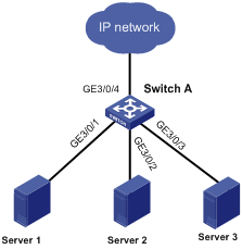
As shown in Figure 1:
· All ports on Switch A are operating in speed autonegotiation mode, with the highest speed of 1000 Mbps.
· GigabitEthernet 3/0/4 provides access to the Internet for the servers.
If the transmission rate of each server in the server cluster is 1000 Mbps, their total transmission rate exceeds the capability of port GigabitEthernet 3/0/4.
To avoid congestion on GigabitEthernet 3/0/4, set 100 Mbps as the only option available for speed negotiation on ports GigabitEthernet 3/0/1, GigabitEthernet 3/0/2, and GigabitEthernet 3/0/3. Then, the transmission rate on each port connected to a server is limited to 100 Mbps.
To set speed options for autonegotiation on an Ethernet interface:
|
Step |
Command |
Remarks |
|
1. Enter system view. |
system-view |
N/A |
|
2. Enter Ethernet interface view. |
interface interface-type interface-number |
N/A |
|
3. Set speed options for autonegotiation. |
speed auto { 10 | 100 | 1000 } * |
The speed and speed auto commands supersede each other, and whichever is configured last takes effect. |
Configuring storm suppression
You can use the storm suppression function to limit the size of a particular type of traffic (broadcast, multicast, or unknown unicast traffic) on an interface. When the broadcast, multicast, or unknown unicast traffic on the interface exceeds this threshold, the system discards packets until the traffic drops below this threshold.
Any of the broadcast-suppression, multicast-suppression, and unicast-suppression commands can suppress storm on a port. The broadcast-suppression, multicast-suppression, and unicast-suppression commands suppress traffic in hardware.
Configuration guidelines
When you configure storm suppression, follow these restrictions and guidelines:
· When you configure the suppression threshold in pps or kbps, the device might convert the configured value into a multiple of a step supported by the chip. As a result, the actual suppression threshold might be different from the configured one. For the suppression threshold that takes effect, see the prompt on the device.
· If you configure two or all of the broadcast-suppression, multicast-suppression, and unicast-suppression commands on an Ethernet interface, you must configure the same threshold. Otherwise, the configuration cannot take effect.
Configuration procedure
To set storm suppression thresholds on one or multiple Ethernet interfaces:
|
Step |
Command |
Remarks |
|
1. Enter system view. |
system-view |
N/A |
|
2. Enter Ethernet interface or subinterface view. |
interface interface-type { interface-number | interface-number.subnumber } |
N/A |
|
3. Enable broadcast suppression and set the broadcast suppression threshold. |
broadcast-suppression { ratio | pps max-pps | kbps max-kbps } |
By default, broadcast traffic is allowed to pass through an interface. |
|
4. Enable multicast suppression and set the multicast suppression threshold. |
multicast-suppression { ratio | pps max-pps | kbps max-kbps } |
By default, multicast traffic is allowed to pass through an interface. |
|
5. Enable unknown unicast suppression and set the unknown unicast suppression threshold. |
unicast-suppression { ratio | pps max-pps | kbps max-kbps } |
By default, unknown unicast traffic is allowed to pass through an interface. |
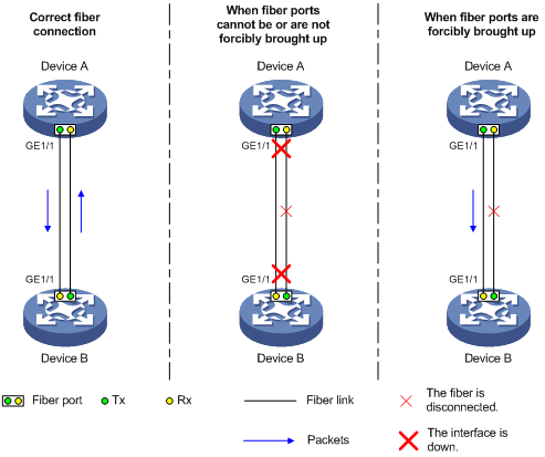
Forcibly bringing up a fiber GE, 10-GE, or 40-GE port
As shown in Figure 2, a fiber GE, 10-GE, or 40-GE port uses separate fibers for transmitting and receiving packets. The physical state of the fiber port is up only when both transmit and receive fibers are physically connected. If one of the fibers is disconnected, the fiber port does not work.
To enable a fiber port to forward traffic over a single link, you can use the port up-mode command. This command brings up a fiber port by force, even when no fiber links or transceiver modules are present. If one fiber link is present and up, the fiber port can forward packets over the link unidirectionally.
Figure 2 Forcibly bring up a fiber GE, 10-GE, or 40-GE port
Configuration restrictions and guidelines
When you forcibly bring up a fiber GE, 10-GE, or 40-GE port, follow these restrictions and guidelines:
· Make sure the port is operating in bridge mode.
· The port up-mode command is mutually exclusive with any of the shutdown, and loopback commands.
· A fiber port forcibly brought up stays physically up whether or not a transceiver module or a fiber connection is present for the port.
· A fiber port forcibly brought up cannot correctly forward traffic if you install a fiber-to-copper converter, 100/1000-Mbps transceiver module, or 100-Mbps transceiver module into the port. To solve the problem, use the undo port up-mode command on the fiber port.
Configuration procedure
To forcibly bring up a fiber GE, 10-GE, or 40-GE port:
|
Step |
Command |
Remarks |
|
1. Enter system view. |
system-view |
N/A |
|
2. Enter fiber port view. |
interface interface-type interface-number |
Only 10-GE or 40-GE fiber ports operating in LAN mode and GE fiber ports support this feature. Copper ports do not support this feature. |
|
3. Forcibly bring up the fiber port. |
port up-mode |
By default, a fiber Ethernet port is not forcibly brought up, and the physical state of a fiber port depends on the physical state of the fibers. |
Setting the MDIX mode of an Ethernet interface
|
|
IMPORTANT: Fiber ports do not support the MDIX mode setting. |
A physical Ethernet interface comprises eight pins, each of which plays a dedicated role. For example, pins 1 and 2 transmit signals, and pins 3 and 6 receive signals. You can use both crossover and straight-through Ethernet cables to connect copper Ethernet interfaces. To accommodate these types of cables, a copper Ethernet interface can operate in one of the following Medium Dependent Interface-Crossover (MDIX) modes:
· MDIX mode—Pins 1 and 2 are receive pins and pins 3 and 6 are transmit pins.
· MDI mode—Pins 1 and 2 are transmit pins and pins 3 and 6 are receive pins.
· AutoMDIX mode—The interface negotiates pin roles with its peer.
To enable the interface to communicate with its peer, set the MDIX mode of the interface mode by using the following guidelines:
· Typically, set the MDIX mode of the interface to AutoMDIX. Set the MDIX mode of the interface to MDI or MDIX only when the device cannot determine the cable type.
· When a straight-through cable is used, set the interface to operate in the MDIX mode different than its peer.
· When a crossover cable is used, perform one of the following operations:
¡ Set the interface to operate in the same MDIX mode as its peer.
¡ Set either end to operate in AutoMDIX mode.
To set the MDIX mode of an Ethernet interface:
|
Step |
Command |
Remarks |
|
1. Enter system view. |
system-view |
N/A |
|
2. Enter Ethernet interface view. |
interface interface-type interface-number |
N/A |
|
3. Set the MDIX mode of the Ethernet interface. |
mdix-mode { automdix | mdi | mdix } |
By default, a copper Ethernet interface operates in auto mode to negotiate pin roles with its peer. |
Setting the connection mode of an Ethernet interface
|
|
IMPORTANT: This command is applicable only to the internal interfaces on an LST1NSM1A1 card (OAP card). |
To ensure communication between the device and the LST1NSM1A1 card in an OAA network, configure the internal interface connecting them to operate in extend connection mode. For more information about the LST1NSM1A1 card, see OAA Configuration Guide.
To set the connection mode of an Ethernet interface:
|
Step |
Command |
Remarks |
|
1. Enter system view. |
system-view |
N/A |
|
2. Enter the view of the internal interface on an LST1NSM1A1 card. |
interface interface-type interface-number |
N/A |
|
3. Set the connection mode of the interface. |
port connection-mode { extend | normal } |
By default, the interface operates in normal connection mode. |
Configuring a Layer 3 Ethernet interface or subinterface
Setting the MTU for an Ethernet interface or subinterface
The value of maximum transmission unit (MTU) affects the fragmentation and reassembly of IP packets. Typically, you do not need to modify the MTU of an interface.
To set the MTU for an Ethernet interface or subinterface:
|
Step |
Command |
Remarks |
|
1. Enter system view. |
system-view |
N/A |
|
2. Enter Ethernet interface or subinterface view. |
interface interface-type { interface-number | interface-number.subnumber } |
N/A |
|
3. Set the MTU. |
mtu size |
The default setting is 1500 bytes. |
Displaying and maintaining an Ethernet interface or subinterface
Execute display commands in any view and reset commands in user view.
|
Task |
Command |
|
Display interface traffic statistics. |
display counters { inbound | outbound } interface [ interface-type [ interface-number | interface-number.subnumber ] ] |
|
Display traffic rate statistics of interfaces in up state over the last sampling interval. |
display counters rate { inbound | outbound } interface [ interface-type [ interface-number | interface-number.subnumber ] ] |
|
Display the operational and status information of the specified interface or all interfaces. |
display interface [ interface-type [ interface-number | interface-number.subnumber ] ] |
|
Display summary information about the specified interface or all interfaces. |
display interface [ interface-type [ interface-number | interface-number.subnumber ] ] brief [ description ] |
|
Display Ethernet interface statistics. |
display ethernet statistics |
|
Clear the interface or subinterface statistics. |
reset counters interface [ interface-type [ interface-number | interface-number.subnumber ] ] |
|
Clear Ethernet interface statistics. |
reset ethernet statistics |