- Table of Contents
- Related Documents
-
| Title | Size | Download |
|---|---|---|
| 01-H3C S12500 MPLS L2VPN Configuration Examples | 166.28 KB |
Contents
Introduction
This document provides examples for configuring MPLS L2VPN through LDP PWs.
MPLS L2VPN is an MPLS-based Layer 2 VPN technology. It can transparently transmit Layer 2 data for different data link layer protocols over an MPLS network.
Prerequisites
The configuration examples in this document were created and verified in a lab environment, and all the devices were started with the factory default configuration. When you are working on a live network, make sure you understand the potential impact of every command on your network.
This document assumes that you have basic knowledge of MPLS L2VPN and LDP.
Example: Configuring LDP PWs
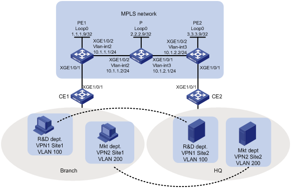
Network requirements
As shown in Figure 1, the MPLS network provides L2VPN services for a customer. Configure LDP PWs between PE 1 and PE 2 so the R&D and Marketing departments use different VPN connections to achieve data isolation.
Requirements analysis
To use LDP PWs to implement MPLS L2VPN, configure two levels of labels:
· Inner labels—PW labels dynamically generated by LDP.
· Outer labels—Public tunnel labels dynamically generated by LDP in this example.
To identify packets to be transported by MPLS L2VPN, configure service instances and match criteria on the CE-facing ports of PEs.
Software version used
This configuration example was created and verified on S12500-CMW710-R7328P02.
Configuration procedures
1. Configure OSPF on the MPLS backbone to ensure IP connectivity within the backbone:
# On PE 1, configure an IP address for Loopback 0.
<PE1> system-view
[PE1] interface loopback 0
[PE1-LoopBack0] ip address 1.1.1.9 32
[PE1-LoopBack0] quit
# On PE 1, create VLAN 2 and assign Ten-GigabitEthernet 1/0/2 to the VLAN.
[PE1] vlan 2
[PE1-vlan2] port Ten-GigabitEthernet 1/0/2
[PE1-vlan2] quit
# On PE 1, configure an IP address for VLAN-interface 2.
[PE1] interface vlan-interface 2
[PE1-Vlan-interface2] ip address 10.1.1.1 24
[PE1-Vlan-interface2] quit
# On PE 1, configure OSPF.
[PE1] ospf
[PE1-ospf-1] area 0
[PE1-ospf-1-area-0.0.0.0] network 10.1.1.0 0.0.0.255
[PE1-ospf-1-area-0.0.0.0] network 1.1.1.9 0.0.0.0
[PE1-ospf-1-area-0.0.0.0] quit
[PE1-ospf-1] quit
# On P, configure an IP address for Loopback 0.
<P> system-view
[P] interface loopback 0
[P-LoopBack0] ip address 2.2.2.9 32
[P-LoopBack0] quit
# On P, create VLAN 2 and assign Ten-GigabitEthernet 1/0/2 to the VLAN.
[P] vlan 2
[P-vlan2] port Ten-GigabitEthernet1/0/2
[P-vlan2] quit
# On P, configure an IP address for VLAN-interface 2.
[P] interface vlan-interface 2
[P-Vlan-interface2] ip address 10.1.1.2 24
[P-Vlan-interface2] quit
# On P, create VLAN 3 and assign Ten-GigabitEthernet 1/0/1 to the VLAN.
[P] vlan 3
[P-vlan3] port Ten-GigabitEthernet1/0/1
[P-vlan3] quit
# On P, configure an IP address for VLAN-interface 3.
[P] interface vlan-interface 3
[P-Vlan-interface3] ip address 10.1.2.1 24
[P-Vlan-interface3] quit
# On P, configure OSPF.
[P] ospf
[P-ospf-1] area 0
[P-ospf-1-area-0.0.0.0] network 10.1.1.0 0.0.0.255
[P-ospf-1-area-0.0.0.0] network 10.1.2.0 0.0.0.255
[P-ospf-1-area-0.0.0.0] network 2.2.2.9 0.0.0.0
[P-ospf-1-area-0.0.0.0] quit
[P-ospf-1] quit
# On PE 2, configure an IP address for Loopback 0.
<PE2> system-view
[PE2] interface loopback 0
[PE2-LoopBack0] ip address 3.3.3.9 32
[PE2-LoopBack0] quit
# On PE 2, create VLAN 3 and assign Ten-GigabitEthernet 1/0/2 to the VLAN.
[PE2] vlan 3
[PE2-vlan3] port Ten-GigabitEthernet 1/0/2
[PE2-vlan3] quit
# On PE 2, configure an IP address for VLAN-interface 3.
[PE2] interface vlan-interface 3
[PE2-Vlan-interface3] ip address 10.1.2.2 24
[PE2-Vlan-interface3] quit
# On PE 2, configure OSPF.
[PE2] ospf
[PE2-ospf-1] area 0
[PE2-ospf-1-area-0.0.0.0] network 10.1.2.0 0.0.0.255
[PE2-ospf-1-area-0.0.0.0] network 3.3.3.9 0.0.0.0
[PE2-ospf-1-area-0.0.0.0] quit
[PE2-ospf-1] quit
2. Configure basic MPLS and MPLS LDP on the MPLS backbone to establish LDP LSPs:
# On PE 1, configure an LSR ID.
[PE1] mpls lsr-id 1.1.1.9
# On PE 1, enable LDP globally.
[PE1] mpls ldp
[PE1-ldp] quit
# On PE 1, enable MPLS and LDP on VLAN-interface 2.
[PE1] interface vlan-interface 2
[PE1-Vlan-interface2] mpls enable
[PE1-Vlan-interface2] mpls ldp enable
[PE1-Vlan-interface2] quit
# On P, configure an LSR ID.
[P] mpls lsr-id 2.2.2.9
# On P, enable LDP globally.
[P] mpls ldp
[P-ldp] quit
# On P, enable MPLS and LDP on VLAN-interface 2.
[P] interface vlan-interface 2
[P-Vlan-interface2] mpls enable
[P-Vlan-interface2] mpls ldp enable
[P-Vlan-interface2] quit
# On P, enable MPLS and LDP on VLAN-interface 3.
[P] interface vlan-interface 3
[P-Vlan-interface3] mpls enable
[P-Vlan-interface3] mpls ldp enable
[P-Vlan-interface3] quit
# On PE 2, configure an LSR ID.
[PE2] mpls lsr-id 3.3.3.9
# On PE 2, enable LDP globally.
[PE2] mpls ldp
[PE2-ldp] quit
# On PE 2, enable MPLS and LDP on VLAN-interface 3.
[PE2] interface vlan-interface 3
[PE2-Vlan-interface3] mpls enable
[PE2-Vlan-interface3] mpls ldp enable
[PE2-Vlan-interface3] quit
3. Configure a service instance for each department and bind the service instances to their respective VPN connections:
# On PE 1, enable MPLS L2VPN globally.
[PE1] l2vpn enable
# On PE 1, create service instance 100 on Ten-GigabitEthernet 1/0/1 to match packets from VLAN 100.
[PE1] interface ten-gigabitethernet1/0/1
[PE1-Ten-GigabitEthernet1/0/1] service-instance 100
[PE1-Ten-GigabitEthernet1/0/1-srv100] encapsulation s-vid 100
[PE1-Ten-GigabitEthernet1/0/1-srv100] quit
# On PE 1, create service instance 200 on Ten-GigabitEthernet 1/0/1 to match packets from VLAN 200.
[PE1-Ten-GigabitEthernet1/0/1] service-instance 200
[PE1-Ten-GigabitEthernet1/0/1-srv200] encapsulation s-vid 200
[PE1-Ten-GigabitEthernet1/0/1-srv200] quit
[PE1-Ten-GigabitEthernet1/0/1] quit
# On PE 1, create cross-connect group vpna, create cross-connect ldp in the group, and bind service instance 100 on Ten-GigabitEthernet 1/0/1 to the cross-connect.
[PE1] xconnect-group vpna
[PE1-xcg-vpna] connection ldp
[PE1-xcg-vpna-ldp] ac interface Ten-GigabitEthernet 1/0/1 service-instance 100
# On PE 1, create an LDP PW for the cross-connect to bind the AC to the PW.
[PE1-xcg-vpna-ldp] peer 3.3.3.9 pw-id 100
[PE1-xcg-vpna-ldp-3.3.3.9-100] quit
[PE1-xcg-vpna-ldp] quit
[PE1-xcg-vpna] quit
# On PE 1, create cross-connect group vpnb, create cross-connect ldp in the group, and bind service instance 200 on Ten-GigabitEthernet 1/0/1 to the cross-connect.
[PE1] xconnect-group vpnb
[PE1-xcg-vpnb] connection ldp
[PE1-xcg-vpnb-ldp] ac interface Ten-GigabitEthernet 1/0/1 service-instance 200
# On PE 1, create an LDP PW for the cross-connect to bind the AC to the PW.
[PE1-xcg-vpnb-ldp] peer 3.3.3.9 pw-id 200
[PE1-xcg-vpnb-ldp-3.3.3.9-200] quit
[PE1-xcg-vpnb-ldp] quit
[PE1-xcg-vpnb] quit
# On PE 2, enable MPLS L2VPN globally.
[PE2] l2vpn enable
# On PE 2, create service instance 100 on Ten-GigabitEthernet 1/0/1 to match packets from VLAN 100.
[PE2] interface ten-gigabitethernet1/0/1
[PE2-Ten-GigabitEthernet1/0/1] service-instance 100
[PE2-Ten-GigabitEthernet1/0/1-srv100] encapsulation s-vid 100
[PE2-Ten-GigabitEthernet1/0/1-srv100] quit
# On PE 2, create service instance 200 on Ten-GigabitEthernet 1/0/1 to match packets from VLAN 200.
[PE2-Ten-GigabitEthernet1/0/1] service-instance 200
[PE2-Ten-GigabitEthernet1/0/1-srv200] encapsulation s-vid 200
[PE2-Ten-GigabitEthernet1/0/1-srv200] quit
[PE2-Ten-GigabitEthernet1/0/1] quit
# On PE 2, create cross-connect group vpna, create cross-connect ldp in the group, and bind service instance 100 on Ten-GigabitEthernet 1/0/1 to the cross-connect.
[PE2] xconnect-group vpna
[PE2-xcg-vpna] connection ldp
[PE2-xcg-vpna-ldp] ac interface Ten-GigabitEthernet 1/0/1 service-instance 100
# On PE 2, create an LDP PW for the cross-connect to bind the AC to the PW.
[PE2-xcg-vpna-ldp] peer 1.1.1.9 pw-id 100
[PE2-xcg-vpna-ldp-1.1.1.9-100] quit
[PE2-xcg-vpna-ldp] quit
[PE2-xcg-vpna] quit
# On PE 2, create cross-connect group vpnb, create cross-connect ldp in the group, and bind service instance 200 on Ten-GigabitEthernet 1/0/1 to the cross-connect.
[PE2] xconnect-group vpnb
[PE2-xcg-vpnb] connection ldp
[PE2-xcg-vpnb-ldp] ac interface Ten-GigabitEthernet 1/0/1 service-instance 200
# On PE 2, create an LDP PW for the cross-connect to bind the AC to the PW.
[PE2-xcg-vpnb-ldp] peer 1.1.1.9 pw-id 200
[PE2-xcg-vpnb-ldp-1.1.1.9-200] quit
[PE2-xcg-vpnb-ldp] quit
[PE2-xcg-vpnb] quit
4. Allow CE access to PEs:
# On CE 1, configure the interface connected to the PE to permit tagged packets from the customer VLANs.
<CE1> system-view
[CE1] vlan 100
[CE1-vlan100] quit
[CE1] vlan 200
[CE1-vlan200] quit
[CE1] interface Ten-GigabitEthernet 1/0/1
[CE1-Ten-GigabitEthernet1/0/1] port link-type trunk
[CE1-Ten-GigabitEthernet1/0/1] port trunk permit vlan 100 200
# Configure other CEs in the same way that CE 1 is configured. (Details not shown.)
Verifying the configuration
# Display L2VPN PW information on PE 1. The output shows that two LDP PWs have been established.
[PE1] display l2vpn pw
Flags: M - main, B - backup, H - hub link, S - spoke link, N - no split horizon
Total number of PWs: 2, 2 up, 0 blocked, 0 down, 0 defect
Xconnect-group Name: vpna
Peer PW ID In/Out Label Proto Flag Link ID State
3.3.3.9 100 65663/65663 LDP M 1 Up
Xconnect-group Name: vpnb
Peer PW ID In/Out Label Proto Flag Link ID State
3.3.3.9 200 65662/65662 LDP M 1 Up
# Display L2VPN PW information on PE 2. The output shows that two LDP PWs have been established.
[PE2] display l2vpn pw
Flags: M - main, B - backup, H - hub link, S - spoke link, N - no split horizon
Total number of PWs: 2, 2 up, 0 blocked, 0 down, 0 defect
Xconnect-group Name: vpna
Peer PW ID In/Out Label Proto Flag Link ID State
1.1.1.9 100 65663/65663 LDP M 1 Up
Xconnect-group Name: vpnb
Peer PW ID In/Out Label Proto Flag Link ID State
1.1.1.9 200 65662/65662 LDP M 1 Up
# Verify that the host and the server in the same VLAN can ping each other. (Details not shown.)
Configuration files
· CE 1 and CE 2:
#
vlan 100
#
vlan 200
#
interface Ten-GigabitEthernet1/0/1
port link-mode bridge
port link-type trunk
port trunk permit vlan 100 200
#
· PE 1:
#
ospf 1
area 0.0.0.0
network 1.1.1.9 0.0.0.0
network 10.1.1.0 0.0.0.255
#
mpls lsr-id 1.1.1.9
#
vlan 2
#
mpls ldp
#
l2vpn enable
#
interface LoopBack0
ip address 1.1.1.9 255.255.255.255
#
interface Vlan-interface2
ip address 10.1.1.1 255.255.255.0
mpls enable
mpls ldp enable
#
interface Ten-GigabitEthernet1/0/1
port link-mode bridge
service-instance 100
encapsulation s-vid 100
service-instance 200
encapsulation s-vid 200
#
interface Ten-GigabitEthernet1/0/2
port link-mode bridge
port access vlan 2
#
xconnect-group vpna
connection ldp
ac interface Ten-GigabitEthernet1/0/1 service-instance 100
peer 3.3.3.9 pw-id 100
#
xconnect-group vpnb
connection ldp
ac interface Ten-GigabitEthernet1/0/1 service-instance 200
peer 3.3.3.9 pw-id 200
#
· P:
#
ospf 1
area 0.0.0.0
network 10.1.1.0 0.0.0.255
network 10.1.2.0 0.0.0.255
network 2.2.2.9 0.0.0.0
#
mpls lsr-id 2.2.2.9
#
vlan 2
#
vlan 3
#
mpls ldp
#
interface LoopBack0
ip address 2.2.2.9 255.255.255.255
#
interface Vlan-interface2
ip address 10.1.1.2 255.255.255.0
mpls enable
mpls ldp enable
#
interface Vlan-interface3
ip address 10.1.2.1 255.255.255.0
mpls enable
mpls ldp enable
#
interface Ten-GigabitEthernet1/0/1
port link-mode bridge
port access vlan 3
#
interface Ten-GigabitEthernet1/0/2
port link-mode bridge
port access vlan 2
#
· PE 2:
#
ospf 1
area 0.0.0.0
network 10.1.2.0 0.0.0.255
network 3.3.3.9 0.0.0.0
#
mpls lsr-id 3.3.3.9
#
vlan 3
#
mpls ldp
#
l2vpn enable
#
interface LoopBack0
ip address 3.3.3.9 255.255.255.255
#
interface Vlan-interface3
ip address 10.1.2.2 255.255.255.0
mpls enable
mpls ldp enable
#
interface Ten-GigabitEthernet1/0/1
port link-mode bridge
service-instance 100
encapsulation s-vid 100
service-instance 200
encapsulation s-vid 200
#
interface Ten-GigabitEthernet1/0/2
port link-mode bridge
port access vlan 3
#
xconnect-group vpna
connection ldp
ac interface Ten-GigabitEthernet1/0/1 service-instance 100
peer 1.1.1.9 pw-id 100
#
xconnect-group vpnb
connection ldp
ac interface Ten-GigabitEthernet1/0/1 service-instance 200
peer 1.1.1.9 pw-id 200
#
Related documentation
· H3C S12500 Routing Switch Series MPLS Command Reference-Release 7328
· H3C S12500 Routing Switch Series MPLS Configuration Guide-Release 7328