- Table of Contents
-
- 05-Layer 3 - IP Routing Configuration Examples
- 00-H3C S12500 OSPF Configuration Examples
- 01-H3C S12500 IS-IS Configuration Examples
- 02-H3C S12500 BGP Configuration Examples
- 03-H3C S12500 Policy-Based Routing Configuration Examples
- 04-H3C S12500 OSPFv3 Configuration Examples
- 05-H3C S12500 IPv6 IS-IS Configuration Examples
- 06-H3C S12500 Routing Policy Configuration Examples
- Related Documents
-
| Title | Size | Download |
|---|---|---|
| 05-H3C S12500 IPv6 IS-IS Configuration Examples | 129.21 KB |
Introduction
This document provides IPv6 IS-IS configuration examples.
Prerequisites
The configuration examples in this document were created and verified in a lab environment, and all the devices were started with the factory default configuration. When you are working on a live network, make sure you understand the potential impact of every command on your network.
This document assumes that you have basic knowledge of IPv6 IS-IS.
Example: Configuring IPv6 IS-IS
Network requirements
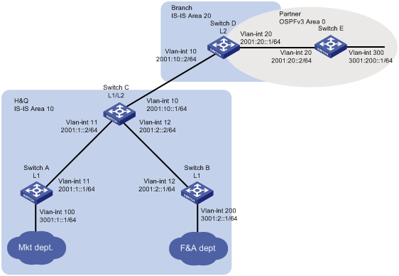
As shown in Figure 1, the company's headquarters and the branch run IPv6 IS-IS. The partner runs OSPFv3.
Configure the switches to meet the following requirements:
· The Marketing department can reach the Finance department, the branch, and the partner.
· The Finance department and the branch cannot reach each other, and the branch does not have a route to the Finance department.
Requirements analysis
To meet the network requirements, you must perform the following tasks:
· Configure Switch A and Switch B in Area 10 as Level-1 routers to allow communication between the Marketing department and the Finance department.
· Configure route redistribution between IPv6 IS-IS and OSPFv3 on Switch D to allow communication between the Marketing department and the partner.
· Configure Switch C to use a prefix list to advertise only network 3001:1::/64 to Level-2. So that the branch does not have a route to the Finance department.
Software version used
This configuration example was created and verified on S12500-CMW710-R7328P02.
Configuration procedures
Configuring Switch A
# Configure an IPv6 address for VLAN-interface 11.
<SwitchA> system-view
[SwitchA] interface vlan-interface 11
[SwitchA-Vlan-interface11] ipv6 address 2001:1::1 64
[SwitchA-Vlan-interface11] quit
# Configure IPv6 addresses for other interfaces, as shown in Figure 1. (Details not shown.)
# Configure IPv6 IS-IS.
[SwitchA] isis 1
[SwitchA-isis-1] is-level level-1
[SwitchA-isis-1] network-entity 10.3001.0001.0001.00
[SwitchA-isis-1] quit
[SwitchA] interface vlan-interface 11
[SwitchA–vlan-interface 11] isis ipv6 enable 1
[SwitchA–vlan-interface 11] quit
[SwitchA] interface vlan-interface 100
[SwitchA–Vlan-interface100] isis ipv6 enable 1
[SwitchA–Vlan-interface100] quit
Configuring Switch B
# Configure an IPv6 address for VLAN-interface 12.
<SwitchB> system-view
[SwitchB] interface vlan-interface 12
[SwitchB-Vlan-interface12] ipv6 address 2001:2::1 64
[SwitchB-Vlan-interface12] quit
# Configure IPv6 addresses for other interfaces, as shown in Figure 1. (Details not shown.)
# Configure IPv6 IS-IS.
[SwitchB] isis 1
[SwitchB-isis-1] ipv6 enable
[SwitchB-isis-1] is-level level-1
[SwitchB-isis-1] network-entity 10.3001.0002.0001.00
[SwitchB-isis-1] quit
[SwitchB] interface vlan-interface 12
[SwitchB–Vlan-interface12] isis ipv6 enable 1
[SwitchB–Vlan-interface12] quit
[SwitchB] interface vlan-interface 200
[SwitchB–Vlan-interface 200] isis ipv6 enable 1
[SwitchB–Vlan-interface 200] quit
Configuring Switch C
# Configure an IPv6 address for VLAN-interface 11.
<SwitchC> system-view
[SwitchC] interface vlan-interface 11
[SwitchC-Vlan-interface11] ipv6 address 2001:1::2 64
[SwitchC-Vlan-interface11] quit
# Configure IPv6 addresses for other interfaces, as shown in Figure 1. (Details not shown.)
# Configure IPv6 IS-IS.
[SwitchC] isis 1
[SwitchC-isis-1] network-entity 10.2001.0010.0001.00
[SwitchC-isis-1] ipv6 enable
[SwitchC-isis-1] quit
[SwitchC] interface vlan-interface 10
[SwitchC–Vlan-interface10] isis ipv6 enable 1
[SwitchC–Vlan-interface10] quit
[SwitchC] interface vlan-interface 11
[SwitchC–Vlan-interface11] isis ipv6 enable 1
[SwitchC–Vlan-interface11] quit
[SwitchC] interface vlan-interface 12
[SwitchC–Vlan-interface12] isis ipv6 enable 1
[SwitchC–Vlan-interface12] quit
# Configure route leaking from Level-1 to Level-2, and use prefix list 1 to advertise only network 3001:1::/64 to Level-2.
[SwitchC] ipv6 prefix-list 1 permit 3001:1:: 64
[SwitchC] isis 1
[SwitchC-isis-1] ipv6 import-route isisv6 level-1 into level-2 filter-policy prefix-list 1
[SwitchC-isis-1] quit
Configuring Switch D
# Configure an IPv6 address for VLAN-interface 10.
<SwitchD> system-view
[SwitchD] interface vlan-interface 10
[SwitchD- Vlan-interface10] ipv6 address 2001:10::2 64
[SwitchD- Vlan-interface10] quit
# Configure IPv6 addresses for other interfaces, as shown in Figure 1. (Details not shown.)
# Configure IPv6 IS-IS.
[SwitchD] isis 1
[SwitchD-isis-1] is-level level-2
[SwitchD-isis-1] network-entity 20.2001.0020.0001.00
[SwitchD-isis-1] ipv6 enable
[SwitchD-isis-1] quit
[SwitchD] interface vlan-interface 10
[SwitchD–Vlan-interface10] isis ipv6 enable 1
[SwitchD–Vlan-interface10] quit
[SwitchD] interface vlan-interface 20
[SwitchD–Vlan-interface20] isis ipv6 enable 1
[SwitchD–Vlan-interface20] quit
# Configure OSPFv3.
[SwitchD] ospfv3
[SwitchD-ospfv3-1] router-id 4.4.4.4
[SwitchD-ospfv3-1] quit
[SwitchD] interface vlan-interface 20
[SwitchD–Vlan-interface20] ospfv3 1 area 0
[SwitchD–Vlan-interface20] quit
# Redistribute OSPFv3 and direct routes into IPv6 IS-IS.
[SwitchD] isis 1
[SwitchD-isis-1-ipv6] import-route ospfv3
[SwitchD-isis-1-ipv6] import-route direct
[SwitchD-isis-1] quit
# Redistribute IPv6 IS-IS and direct routes into OSPFv3.
[SwitchD] ospfv3 1
[SwitchD-ospfv3-1] import-route isisv6 1
[SwitchD-ospfv3-1] import-route direct
Configuring Switch E
# Configure an IPv6 address for VLAN-interface 20.
<SwitchE> system-view
[SwitchE] interface Vlan-interface20
[SwitchE-Vlan-interface12] ipv6 address 2001:20::2 64
[SwitchE-Vlan-interface12] quit
# Configure IPv6 addresses for other interfaces, as shown in Figure 1. (Details not shown.)
# Configure OSPFv3.
[SwitchE] ospfv3
[SwitchE-ospfv3-1] router-id 5.5.5.5
[SwitchE-ospfv3-1] quit
[SwitchE] interface vlan-interface 20
[SwitchE–Vlan-interface 20] ospfv3 1 area 0
[SwitchE–Vlan-interface 20] quit
[SwitchE] interface vlan-interface 300
[SwitchE–Vlan-interface 300] ospfv3 1 area 0
[SwitchE–Vlan-interface 300] quit
Verifying the configuration
# Verify that the branch can reach the Marketing department, but cannot reach the Finance department.
[SwitchD] display isis route ipv6
Route information for IS-IS(1)
------------------------------
Level-2 IPv6 Forwarding Table
-----------------------------
Destination : 2001:10:: PrefixLen: 64
Flag : D/L/- Cost : 10
Next Hop : Direct Interface: Vlan10
Destination : 2001:1:: PrefixLen: 64
Flag : R/-/- Cost : 20
Next Hop : FE80::7625:8AFF:FE02:4D13 Interface: Vlan10
Destination : 2001:2:: PrefixLen: 64
Flag : R/-/- Cost : 20
Next Hop : FE80::7625:8AFF:FE02:4D13 Interface: Vlan10
Destination : 3001:1:: PrefixLen: 64
Flag : R/-/- Cost : 30
Next Hop : FE80::7625:8AFF:FE02:4D13 Interface: Vlan10
Flags: D-Direct, R-Added to Rib, L-Advertised in LSPs, U-Up/Down Bit Set
# Verify that the company can communicate with the partner.
· Display the IPv6 IS-IS routing table on Switch C.
[SwitchC] display isis route ipv6 level-2
Route information for IS-IS(1)
------------------------------
Level-2 IPv6 Forwarding Table
-----------------------------
Destination : 2001:10:: PrefixLen: 64
Flag : D/L/- Cost : 10
Next Hop : Direct Interface: Vlan10
Destination : 2001:1:: PrefixLen: 64
Flag : D/L/- Cost : 10
Next Hop : Direct Interface: Vlan11
Destination : 2001:2:: PrefixLen: 64
Flag : D/L/- Cost : 10
Next Hop : Direct Interface: Vlan12
Destination : 2001:20:: PrefixLen: 64
Flag : R/L/- Cost : 20
Next Hop : FE80::BAAF:67FF:FE30:3304 Interface: Vlan10
Destination : 3001:200:: PrefixLen: 64
Flag : R/-/- Cost : 20
Next Hop : FE80::BAAF:67FF:FE30:3304 Interface: Vlan10
Flags: D-Direct, R-Added to Rib, L-Advertised in LSPs, U-Up/Down Bit Set
· Ping 3001:200::1 from Switch C.
[SwitchC] ping ipv6 3001:200::1
Ping6(56 data bytes) 2001:10::1 --> 3001:200::1, press CTRL_C to break
56 bytes from 3001:200::1, icmp_seq=0 hlim=63 time=7.230 ms
56 bytes from 3001:200::1, icmp_seq=1 hlim=63 time=3.449 ms
56 bytes from 3001:200::1, icmp_seq=2 hlim=63 time=2.779 ms
56 bytes from 3001:200::1, icmp_seq=3 hlim=63 time=2.652 ms
56 bytes from 3001:200::1, icmp_seq=4 hlim=63 time=2.558 ms
--- Ping6 statistics for 3001:200::1 ---
5 packet(s) transmitted, 5 packet(s) received, 0.0% packet loss
round-trip min/avg/max/std-dev = 2.558/3.734/7.230/1.776 ms
Configuration files
· Switch A:
#
isis 1
is-level level-1
network-entity 10.3001.0001.0001.00
#
ipv6 enable
#
vlan 11
#
vlan 100
#
interface Vlan-interface11
isis ipv6 enable 1
ipv6 address 2001:1::1/64
#
interface Vlan-interface100
isis ipv6 enable 1
ipv6 address 3001:1::1/64
#
· Switch B:
#
isis 1
is-level level-1
network-entity 10.3001.0002.0001.00
#
ipv6 enable
#
vlan 12
#
vlan 200
#
interface Vlan-interface12
isis ipv6 enable 1
ipv6 address 2001:2::1/64
#
interface Vlan-interface200
isis ipv6 enable 1
ipv6 address 3001:2::1/64
#
· Switch C:
#
isis 1
network-entity 10.2001.0010.0001.00
ipv6 import-route isisv6 level-1 into level-2 filter-policy prefix-list 1
ipv6 enable
#
vlan 11 to 13
#
interface Vlan-interface11
isis ipv6 enable 1
ipv6 address 2001:1::2/64
#
interface Vlan-interface12
isis ipv6 enable 1
ipv6 address 2001:2::2/64
#
interface Vlan-interface13
isis ipv6 enable 1
ipv6 address 2001:10::1/64
#
ipv6 prefix-list 1 index 10 permit 3001:1:: 64
#
· Switch D:
#
isis 1
is-level level-2
network-entity 20.2001.0020.0001.00
import-route direct
import-route ospfv3 1
#
ipv6 enable
#
ospfv3 1
router-id 4.4.4.4
area 0.0.0.0
import-route direct
import-route isisv6 1
#
vlan 10
#
vlan 20
#
interface Vlan-interface10
isis ipv6 enable 1
ipv6 address 2001:10::2/64
#
interface Vlan-interface20
ospfv3 1 area 0.0.0.0
ipv6 address 2001:20::1/64
#
· Switch E:
#
ospfv3 1
router-id 5.5.5.5
area 0.0.0.0
#
vlan 20
#
vlan 300
#
interface Vlan-interface20
ospfv3 1 area 0
ipv6 address 2001:20::2/64
#
interface Vlan-interface300
ospfv3 1 area 0
ipv6 address 3001:200::1/64
#
Related documentation
· H3C S12500 Routing Switch Series Layer 3—IP Routing Command Reference-Release 7328
· H3C S12500 Routing Switch Series Layer 3—IP Routing Configuration Guide-Release 7328