- Table of Contents
-
- 05-Layer 3 - IP Routing Configuration Examples
- 00-H3C S12500 OSPF Configuration Examples
- 01-H3C S12500 IS-IS Configuration Examples
- 02-H3C S12500 BGP Configuration Examples
- 03-H3C S12500 Policy-Based Routing Configuration Examples
- 04-H3C S12500 OSPFv3 Configuration Examples
- 05-H3C S12500 IPv6 IS-IS Configuration Examples
- 06-H3C S12500 Routing Policy Configuration Examples
- Related Documents
-
| Title | Size | Download |
|---|---|---|
| 01-H3C S12500 IS-IS Configuration Examples | 129.36 KB |
Introduction
This document provides IS-IS configuration examples.
Prerequisites
The configuration examples in this document were created and verified in a lab environment, and all the devices were started with the factory default configuration. When you are working on a live network, make sure you understand the potential impact of every command on your network.
This document assumes that you have basic knowledge of IS-IS.
Example: Configuring IS-IS
Network requirements
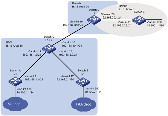
As shown in Figure 1, the company's headquarters and the branch run IS-IS. The partner runs OSPF.
Configure the switches to meet the following requirements:
· The marketing department can reach the finance department, the branch, and the partner.
· The finance department and the branch cannot reach each other, and the branch does not have a route to the finance department.
· When the IS-IS process on Switch C restarts, the communication is not interrupted.
Requirements analysis
To allow communication between the marketing department and the finance department, configure Switch A and Switch B in Area 10 as Level-1 routers.
To allow communication between the marketing department and the partner, configure route redistribution between IS-IS and OSPF on Switch D.
To ensure that the branch does not have a route to the finance department, configure Switch C to use a prefix list to advertise only network 10.100.1.0/24 to Level-2.
To ensure that the communication is not interrupted when the IS-IS process on Switch C restarts, enable IS-IS Graceful Restart (GR) on Switch C.
Software version used
This configuration example was created and verified on S12500-CMW710-R7328P02.
Configuration restrictions and guidelines
To avoid blackhole routes, do not change the network topology during the IS-IS GR process.
Configuration procedures
Configuring Switch A
# Configure an IP address for VLAN-interface 11.
<SwitchA> system-view
[SwitchA] interface vlan-interface 11
[SwitchA-Vlan-interface11] ip address 192.168.1.1 24
[SwitchA-Vlan-interface11] quit
# Configure IP addresses for other interfaces, as shown in Figure 1. (Details not shown.)
# Configure IS-IS.
[SwitchA] isis 1
[SwitchA-isis-1] is-level level-1
[SwitchA-isis-1] network-entity 10.1921.6800.1001.00
[SwitchA-isis-1] quit
[SwitchA] interface vlan-interface 11
[SwitchA–Vlan-interface11] isis enable 1
[SwitchA–Vlan-interface11] quit
[SwitchA] interface vlan-interface 100
[SwitchA–Vlan-interface100] isis enable 1
[SwitchA–Vlan-interface100] quit
Configuring Switch B
# Configure an IP address for VLAN-interface 12.
<SwitchB> system-view
[SwitchB] interface vlan-interface 12
[SwitchB-Vlan-interface12] ip address 192.168.2.1 24
[SwitchB-Vlan-interface12] quit
# Configure IP addresses for other interfaces, as shown in Figure 1. (Details not shown.)
# Configure IS-IS.
[SwitchB] isis 1
[SwitchB-isis-1] is-level level-1
[SwitchB-isis-1] network-entity 10.1921.6800.2001.00
[SwitchB-isis-1] quit
[SwitchB] interface vlan-interface 12
[SwitchB–Vlan-interface12] isis enable 1
[SwitchB–Vlan-interface12] quit
[SwitchB] interface vlan-interface 200
[SwitchB–Vlan-interface 200] isis enable 1
[SwitchB–Vlan-interface 200] quit
Configuring Switch C
# Configure an IP address for VLAN-interface 11.
<SwitchC> system-view
[SwitchC] interface vlan-interface 11
[SwitchC-Vlan-interface11] ip address 192.168.1.2 24
[SwitchC-Vlan-interface11] quit
# Configure IP addresses for other interfaces, as shown in Figure 1. (Details not shown.)
# Configure IS-IS.
[SwitchC] isis 1
[SwitchC-isis-1] network-entity 10.1921.6801.0001.00
[SwitchC-isis-1] quit
[SwitchC] interface vlan-interface 10
[SwitchC–Vlan-interface10] isis enable 1
[SwitchC–Vlan-interface10] quit
[SwitchC] interface vlan-interface 11
[SwitchC–Vlan-interface11] isis enable 1
[SwitchC–Vlan-interface11] quit
[SwitchC] interface vlan-interface 12
[SwitchC–Vlan-interface12] isis enable 1
[SwitchC–Vlan-interface12] quit
# Configure route leaking from Level-1 to Level-2, and use prefix list 1 to advertise only network 10.100.1.0/24 to Level-2.
[SwitchC] ip prefix-list 1 permit 10.100.1.0 24
[SwitchC] isis 1
[SwitchC-isis-1] import-route isis level-1 into level-2 filter-policy prefix-list 1
# Enable IS-IS GR.
[SwitchC-isis-1] graceful-restart
[SwitchC-isis-1] quit
Configuring Switch D
# Configure an IP address for VLAN-interface 10.
<SwitchD> system-view
[SwitchD] interface vlan-interface 10
[SwitchD- Vlan-interface10] ip address 192.168.10.2 24
[SwitchD- Vlan-interface10] quit
# Configure IP addresses for other interfaces, as shown in Figure 1. (Details not shown.)
# Configure IS-IS.
[SwitchD] isis 1
[SwitchD-isis-1] is-level level-2
[SwitchD-isis-1] network-entity 20.1921.6802.0001.00
[SwitchD-isis-1] quit
[SwitchD] interface vlan-interface 10
[SwitchD–Vlan-interface10] isis enable 1
[SwitchD–Vlan-interface10] quit
[SwitchD] interface vlan-interface 20
[SwitchD–Vlan-interface20] isis enable 1
[SwitchD–Vlan-interface20] quit
# Configure OSPF.
[SwitchD] ospf
[SwitchD-ospf-1] area 0
[SwitchD-ospf-1-area-0.0.0.0] network 192.168.20.0 0.0.0.255
[SwitchD-ospf-1-area-0.0.0.0] quit
[SwitchD-ospf-1] quit
# Redistribute OSPF and direct routes into IS-IS
[SwitchD] isis 1
[SwitchD-isis-1] import-route ospf
[SwitchD-isis-1] import-route direct
[SwitchD-isis-1] quit
# Redistribute IS-IS and direct routes into OSPF.
[SwitchD] ospf 1
[SwitchD-ospf-1] import-route isis 1
[SwitchD-ospf-1] import-route direct
Configuring Switch E
# Configure an IP address for VLAN-interface 20.
<SwitchE> system-view
[SwitchE] interface Vlan-interface20
[SwitchE-Vlan-interface12] ip address 192.168.20.2 24
[SwitchE-Vlan-interface12] quit
# Configure IP addresses for other interfaces, as shown in Figure 1. (Details not shown.)
# Configure OSPF.
[SwitchE] ospf
[SwitchE-ospf-1] area 0
[SwitchE-ospf-1-area-0.0.0.0] network 192.168.20.0 0.0.0.255
[SwitchE-ospf-1-area-0.0.0.0] network 10.200.1.0 0.0.0.255
[SwitchE-ospf-1-area-0.0.0.0] quit
[SwitchE-ospf-1] quit
Verifying the configuration
# Verify that the branch can reach the marketing department, but cannot reach the finance department.
[SwitchD] display isis route
Route information for IS-IS(1)
------------------------------
Level-2 IPv4 Forwarding Table
-----------------------------
IPv4 Destination IntCost ExtCost ExitInterface NextHop Flags
-------------------------------------------------------------------------------
192.168.10.0/24 10 NULL Vlan10 Direct D/L/-
192.168.1.0/24 20 NULL Vlan10 192.168.10.1 R/-/-
10.100.1.0/24 30 NULL Vlan10 192.168.10.1 R/-/-
192.168.2.0/24 20 NULL Vlan10 192.168.10.1 R/-/-
Flags: D-Direct, R-Added to Rib, L-Advertised in LSPs, U-Up/Down Bit Set
# Verify that the company can communicate with the partner.
· Display the IS-IS routing table on Switch C.
[SwitchC] display isis route
Route information for IS-IS(1)
------------------------------
Level-1 IPv4 Forwarding Table
-----------------------------
IPv4 Destination IntCost ExtCost ExitInterface NextHop Flags
-------------------------------------------------------------------------------
192.168.10.0/24 10 NULL Vlan10 Direct D/L/-
192.168.1.0/24 10 NULL Vlan11 Direct D/L/-
10.100.1.0/24 20 NULL Vlan11 192.168.1.1 R/L/-
10.100.2.0/24 20 NULL Vlan12 192.168.2.1 R/-/-
192.168.2.0/24 10 NULL Vlan12 Direct D/L/-
Flags: D-Direct, R-Added to Rib, L-Advertised in LSPs, U-Up/Down Bit Set
Level-2 IPv4 Forwarding Table
-----------------------------
IPv4 Destination IntCost ExtCost ExitInterface NextHop Flags
-------------------------------------------------------------------------------
192.168.10.0/24 10 NULL Vlan10 Direct D/L/-
10.200.1.0/24 10 0 Vlan10 192.168.10.2 R/-/-
192.168.20.0/24 10 0 Vlan10 192.168.10.2 R/-/-
192.168.1.0/24 10 NULL Vlan11 Direct D/L/-
192.168.2.0/24 10 NULL Vlan12 Direct D/L/-
Flags: D-Direct, R-Added to Rib, L-Advertised in LSPs, U-Up/Down Bit Set
· Ping 10.200.1.1 from Switch C.
[SwitchC] ping 10.200.1.1
Ping 10.200.1.1 (10.200.1.1): 56 data bytes, press CTRL_C to break
56 bytes from 10.200.1.1: icmp_seq=0 ttl=254 time=1.862 ms
56 bytes from 10.200.1.1: icmp_seq=1 ttl=254 time=2.969 ms
56 bytes from 10.200.1.1: icmp_seq=2 ttl=254 time=1.402 ms
56 bytes from 10.200.1.1: icmp_seq=3 ttl=254 time=1.324 ms
56 bytes from 10.200.1.1: icmp_seq=4 ttl=254 time=1.510 ms
--- Ping statistics for 10.200.1.1 ---
5 packet(s) transmitted, 5 packet(s) received, 0.0% packet loss
round-trip min/avg/max/std-dev = 1.324/1.813/2.969/0.606 ms
# Verify that the communication is not interrupted when the IS-IS process restarts.
· Ping Switch B from Switch A.
[SwitchA] ping -c 10000 10.100.2.1
Ping 10.100.2.1 (10.100.2.1): 56 data bytes, press CTRL_C to break
56 bytes from 10.100.2.1: icmp_seq=0 ttl=254 time=1.185 ms
56 bytes from 10.100.2.1: icmp_seq=1 ttl=254 time=1.087 ms
…
· Restart the IS-IS process on Switch C.
[SwitchC] reset isis all graceful-restart
Reset IS-IS process? [Y/N] :y
# Ping Switch B from Switch A.
[SwitchA] ping -c 10000 10.100.2.1
Ping 10.100.2.1 (10.100.2.1): 56 data bytes, press CTRL_C to break
56 bytes from 10.100.2.1: icmp_seq=0 ttl=254 time=1.185 ms
56 bytes from 10.100.2.1: icmp_seq=1 ttl=254 time=1.087 ms
56 bytes from 13.13.13.3: icmp_seq=2 ttl=254 time=1.672 ms
56 bytes from 13.13.13.3: icmp_seq=3 ttl=254 time=1.751 ms
56 bytes from 13.13.13.3: icmp_seq=4 ttl=254 time=1.816 ms
56 bytes from 13.13.13.3: icmp_seq=5 ttl=254 time=1.814 ms
# Check the IS-IS GR state on Switch C.
[SwitchC] display isis graceful-restart status
Restart information for IS-IS(1)
--------------------------------
Restart status: COMPLETE
Restart phase: Finish
Restart t1: 3, count 10; Restart t2: 60; Restart t3: 300
SA Bit: supported
Level-1 restart information
---------------------------
Total number of interfaces: 3
Number of waiting LSPs: 0
Level-2 restart information
---------------------------
Total number of interfaces: 3
Number of waiting LSPs: 0
Configuration files
#
isis 1
is-level level-1
network-entity 10.1921.6800.1001.00
#
vlan 11
#
vlan 100
#
interface Vlan-interface11
ip address 192.168.1.1 255.255.255.0
isis enable 1
#
interface Vlan-interface100
ip address 10.100.1.1 255.255.255.0
isis enable 1
#
· Switch B:
#
isis 1
is-level level-1
network-entity 10.1921.6800.2001.00
#
vlan 12
#
vlan 200
#
interface Vlan-interface12
ip address 192.168.2.1 255.255.255.0
isis enable 1
#
interface Vlan-interface200
ip address 10.100.2.1 255.255.255.0
isis enable 1
#
· Switch C:
#
isis 1
graceful-restart
network-entity 10.1921.6801.0001.00
import-route isis level-1 into level-2 filter-policy prefix-list 1
#
vlan 11 to 13
#
interface Vlan-interface11
ip address 192.168.1.2 255.255.255.0
isis enable 1
#
interface Vlan-interface12
ip address 192.168.2.2 255.255.255.0
isis enable 1
#
interface Vlan-interface13
ip address 192.168.10.1 255.255.255.0
isis enable 1
#
ip prefix-list 1 index 10 permit 10.100.1.0 24
#
· Switch D:
#
isis 1
is-level level-2
network-entity 20.1921.6802.0001.00
import-route direct
import-route ospf 1
#
ospf 1
import-route direct
import-route isis 1
area 0.0.0.0
network 192.168.20.0 0.0.0.255
#
vlan 10
#
vlan 20
#
interface Vlan-interface10
ip address 192.168.10.2 255.255.255.0
isis enable 1
#
interface Vlan-interface20
ip address 192.168.20.1 255.255.255.0
#
· Switch E:
#
ospf 1
area 0.0.0.0
network 10.200.1.0 0.0.0.255
network 192.168.20.0 0.0.0.255
#
vlan 20
#
vlan 300
#
interface Vlan-interface20
ip address 192.168.20.2 255.255.255.0
#
interface Vlan-interface300
ip address 10.200.1.1 255.255.255.0
#
Related documentation
· H3C S12500 Routing Switch Series Layer 3—IP Routing Command Reference-Release 7328
· H3C S12500 Routing Switch Series Layer 3—IP Routing Configuration Guide-Release 7328