- Table of Contents
-
- 04-Layer 2 - LAN Switching Configuration Guide
- 00-Preface
- 01-VLAN Configuration
- 02-MAC Address Table Configuration
- 03-Spanning Tree Configuration
- 04-Ethernet Link Aggregation Configuration
- 05-Port Isolation Configuration
- 06-QinQ Configuration
- 07-VLAN Mapping Configuration
- 08-BPDU Tunneling Configuration
- 09-GVRP Configuration
- 10-Loopback Detection Configuration
- 11-VLAN Termination Configuration
- 12-MAC-in-MAC Configuration
- 13-LLDP Configuration
- 14-MVRP Configuration
- Related Documents
-
| Title | Size | Download |
|---|---|---|
| 11-VLAN Termination Configuration | 306.77 KB |
VLAN termination networking solutions
VLAN termination configuration task list
Configuring unambiguous QinQ termination
Configuring ambiguous QinQ termination
Enabling a VLAN termination-enabled interface to transmit broadcast and multicast packets
Configuring the TPID for VLAN-tagged packets
VLAN termination configuration examples
Unambiguous QinQ termination configuration example
Ambiguous QinQ termination configuration example
Ambiguous QinQ termination configuration example (lite solution)
Configuration example for QinQ termination supporting DHCP relay
Configuring VLAN termination
The switch does not support QinQ termination when it is operating in standard mode. For more information about the commands of system operating modes, see Fundamentals Command Reference.
Overview
VLAN termination assigns a received VLAN-tagged packet to the corresponding interface according to its VLAN tag, and then the interface removes its VLAN tags, and forwards it through Layer 3 or processes it in another way. Before sending a packet, the port adds VLAN tags to the packet according to the VLAN termination configuration on the port.
VLAN termination types
VLAN termination includes the following types:
· Dot1q termination—Terminates packets which carry one or more layers of VLAN tags and whose outermost VLAN tag matches the number of the receiving VLAN interface. Packets sent out of the VLAN interface are tagged with the ID of that VLAN. By default, Dot1q termination is enabled on all VLAN interfaces.
· QinQ termination—Terminates packets which carry two or more layers of VLAN tags and whose outermost VLAN tag matches the number of the receiving VLAN interface. Packets sent out of a QinQ termination interface are double-tagged.
Application scenarios
Inter-VLAN communication
Hosts in different VLANs cannot directly communicate with each other. You can use Layer 3 routing to allow all VLANs to communicate. To allow the specified VLANs to communicate, configure VLAN termination on VLAN interfaces.
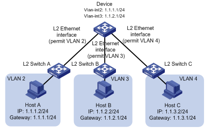
As shown in Figure 1, Host A belongs to VLAN 2, Host B belongs to VLAN 3, and Host C belongs to VLAN 4. Create VLAN-interface 2 and VLAN-interface 3 on the device, and specify Host A's gateway IP address as 1.1.1.1/24 and Host B's gateway IP address as 1.1.2.1/24. With the configuration, Host A and Host B can communicate at Layer 3 through VLAN interfaces. When VLAN-interface 2 receives a packet from Host A, the interface removes the VLAN tag 2 of the packet and forwards the packet to VLAN-interface 3. VLAN-interface 3 then tags the packet with VLAN 3 and forwards it to Host B. The packet sent from Host B to Host A is processed in the same way.
Because VLAN-interface 4 is not created on the device, the device cannot terminate packets from Host C. As a result, Host C cannot communicate with Host A or Host B.
Figure 1 VLAN termination for inter-VLAN communication
LAN-WAN communication
Most packets sent out of LANs carry VLAN tags, but some WAN protocols such as ATM, Frame Relay, and PPP cannot recognize VLAN-tagged packets. Therefore, before sending VLAN-tagged packets to a WAN, the sending port must locally record VLAN information and remove VLAN tags from the packets. VLAN termination can help implement this purpose. You can configure VLAN interfaces to enable LAN-WAN communication.
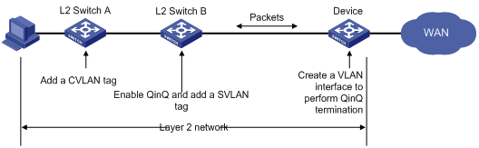
As shown in Figure 2, the VLANs of the customer network are called customer VLANs (CVLANs), and the VLANs of the service provider network are called service provider VLANs (SVLANs). When a packet carrying a CVLAN tag enters the service provider network, it is tagged with a SVLAN tag, and forwarded based on the SVLAN tag. When the packet is to be forwarded to an external WAN, the gateway (Device) must perform VLAN termination for the packet and remove the two layers of VLAN tags from the packet before sending the packet to the WAN.
Figure 2 VLAN termination enables LAN-WAN communication
VLAN termination networking solutions
The following QinQ termination networking solutions are available.
Traditional solution
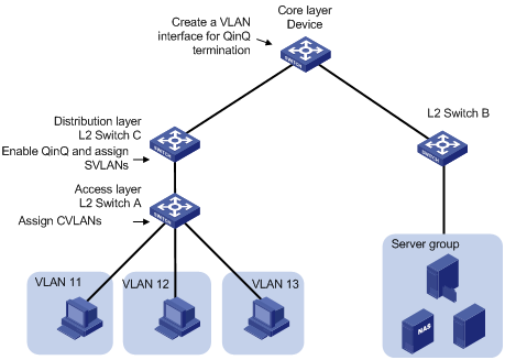
As shown in Figure 3, configure the QinQ feature on the distribution layer devices and configure QinQ termination on core layer devices. In a configuration example, the traditional networking solution is used unless the lite solution is marked for the configuration example.
Figure 3 Traditional QinQ termination networking solution
Lite solution
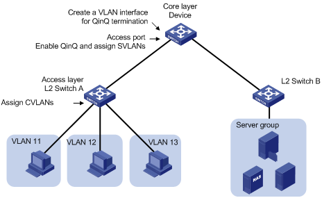
As shown in Figure 4, configure both the QinQ feature and QinQ termination on core layer devices, and you do not need to configure the distribution layer devices. When you use the lite solution and create a VLAN interface on the core layer devices for QinQ termination, make sure the inner VLAN IDs (CVLAN IDs) to be terminated do not include the VLAN interface number.
Figure 4 Lite QinQ termination networking solution
VLAN termination configuration task list
|
Task |
Remarks |
|
|
Use at least one method. |
||
|
Enabling a VLAN termination-enabled interface to transmit broadcast and multicast packets |
Optional. |
|
|
Optional. |
||
Configuring QinQ termination
QinQ termination includes both unambiguous and ambiguous QinQ termination. Unambiguous QinQ termination allows you to specify only one VLAN ID to be added to packets as the inner VLAN tag. Ambiguous QinQ termination allows you to specify a range of VLAN IDs, in which a VLAN can be added to packets as the inner VLAN tag.
QinQ termination enables a VLAN interface to terminate packets whose outermost VLAN tag matches the VLAN interface number, and to prohibit any other VLAN-tagged packets from passing through.
When QinQ termination is configured, the interface uses the following procedures to process packets:
· When the interface receives a packet, it removes the outermost two layers of VLAN tags of the packet.
· When the interface sends out a packet, it tags the packet with two layers of VLAN IDs. The outer VLAN ID is the VLAN interface number. The inner VLAN ID is determined based on the packet types.
· The interface determines the inner VLAN ID by using the following rules:
¡ For a DHCP relay packet, the interface searches the DHCP relay agent bindings to obtain the inner VLAN ID.
¡ For an IPv4 or MPLS packet, the interface searches the ARP table with a specified destination IP address to obtain the inner VLAN ID.
· If the obtained VLAN ID matches the inner VLAN ID specified in the QinQ termination, the interface adds the matched inner VLAN tag to the packet.
|
|
IMPORTANT: To obtain the correct VLAN ID, make sure the Layer 2 physical interface to which the VLAN interface is bound maintains the most recent ARP entries. To do that, execute the reset arp interface command in user view on the Layer 2 physical interface when the QinQ termination configuration on the VLAN interface is changed. For more information about this command, see Layer 3—IP Services Command Reference. |
Configuring unambiguous QinQ termination
|
Step |
Command |
Remarks |
|
1. Enter system view. |
system-view |
N/A |
|
2. Enter VLAN interface view. |
interface vlan-interface interface-number |
N/A |
|
3. Enable QinQ termination on the interface and specify the VLAN ID that the interface adds to packets as the inner VLAN tag before sending them out. |
second-dot1q vlan-id |
By default, QinQ termination is disabled and the interface processes only the outermost VLAN tag of packets. A VLAN interface always adds its interface number as the outer VLAN tag to the packets it sends out. |
Configuring ambiguous QinQ termination
|
Step |
Command |
Remarks |
|
1. Enter system view. |
system-view |
N/A |
|
2. Enter VLAN interface view. |
interface vlan-interface interface-number |
N/A |
|
3. Enable QinQ termination on the interface and specify a list of VLAN IDs that the interface can add to packets as the inner VLAN tag before sending them out. |
second-dot1q { vlan-list | any } |
By default, QinQ termination is disabled and the interface processes only the outermost VLAN tag of packets. A VLAN interface always adds its interface number as the outer VLAN tag to the packets it sends out. |
Enabling a VLAN termination-enabled interface to transmit broadcast and multicast packets
By default, an ambiguous QinQ termination-enabled interface drops broadcast and multicast packets they receive, instead of transmitting them. You can enable an interface configured with ambiguous QinQ termination to transmit broadcast and multicast packets.
To enable a VLAN termination-enabled interface to transmit broadcast and multicast packets:
|
Step |
Command |
Remarks |
|
1. Enter system view. |
system-view |
N/A |
|
2. Enter VLAN interface view. |
interface vlan-interface interface-number |
N/A |
|
3. Enable the interface to transmit broadcast and multicast packets. |
vlan-termination broadcast enable |
By default, an ambiguous QinQ termination-enabled interface does not transmit broadcast and multicast packets. |
Configuring the TPID for VLAN-tagged packets
To configure VLAN termination on a VLAN interface, set the TPID value in the outermost VLAN tag of packets received and sent by the Layer 2 physical interface bound to that VLAN interface. With the configuration, the VLAN interface checks the TPID value in the outermost VLAN tag of each received packet, and then processes the packet as a VLAN-tagged packet only when the TPID value matches the configured value.
If the TPID is not specified, the TPID value in the outermost VLAN tag of packets has a default value of 0x8100. For information about setting the TPID value in the VLAN tag of packets on a Layer 2 physical interface, see "Configuring QinQ."
You can set a non-default TPID value only for a QinQ termination network only in the lite solution. For more information, see "Lite solution."
VLAN termination configuration examples
|
|
NOTE: By default, Ethernet interfaces, VLAN interfaces, and aggregate interfaces are in DOWN state. To configure such an interface, use the undo shutdown command to bring it up first. |
Unambiguous QinQ termination configuration example
Network requirements
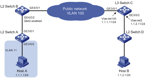
As shown in Figure 5, Host A connects to Layer 2 Switch A and belongs to VLAN 11. Host B connects to Layer 2 Switch D, which supports only single VLAN-tagged packets. With QinQ enabled, Layer 2 Switch B adds an outer VLAN tag 100 to packets whose inner VLAN ID is 11 before forwarding the packets.
Configure QinQ termination so that Host A can communicate with Host B.
Configuration considerations
Configure unambiguous QinQ termination to enable Layer 3 communication between Host A Host B through VLAN interfaces. The following process briefly describes how unambiguous QinQ termination is used for packet transmission between Host A and Host B:
1. When a packet from Host A is sent to Layer 3 Switch C by Layer 2 Switch B, it includes the outer VLAN tag 100 and the inner VLAN tag 11.
2. When the packet arrives at VLAN-interface 100 on Layer 3 Switch C, the interface removes the two VLAN tags before it forwards the packet at Layer 3.
3. When a packet from Host B arrives at Layer 3 Switch C, VLAN-interface 100 adds its interface number as the outer VLAN tag to the packet. VLAN-interface 100 also adds the inner VLAN tag to the packet if the inner VLAN ID specified by the second-dot1q command matches the VLAN ID that is associated with the destination IP address of Host A in the ARP table. This example uses VLAN 11 as the inner VLAN tag.
4. On Layer 2 Switch B, GigabitEthernet 4/0/2 is a trunk port and the PVID is 100. When the packet is received, the interface removes the outer VLAN tag and sends the single-tagged packet to Layer 2 Switch A.
Configuration procedure
1. Configure Host A and Host B:
¡ Configure Host A's IP address as 1.1.1.1/24, and gateway IP address as 1.1.1.11/24.
¡ Configure Host B's IP address as 1.1.2.1/24, and gateway IP address as 1.1.2.11/24.
2. Configure Layer 2 Switch A:
# Assign GigabitEthernet 3/0/2 to VLAN 11.
<L2_SwitchA> system-view
[L2_SwitchA] vlan 11
[L2_SwitchA-vlan11] port GigabitEthernet 3/0/2
[L2_SwitchA-vlan11] quit
# Configure GigabitEthernet 3/0/1 as a hybrid port and assign the port to VLAN 11 as a tagged member.
[L2_SwitchA] interface GigabitEthernet 3/0/1
[L2_SwitchA-GigabitEthernet3/0/1] port link-type hybrid
[L2_SwitchA-GigabitEthernet3/0/1] port hybrid vlan 11 tagged
3. Configure Layer 2 Switch B:
# Configure GigabitEthernet 4/0/2 as a trunk port and assign the port to VLAN 100.
<L2_SwitchB> system-view
[L2_SwitchB] interface GigabitEthernet 4/0/2
[L2_SwitchB-GigabitEthernet4/0/2] port link-type trunk
[L2_SwitchB-GigabitEthernet4/0/2] port trunk permit vlan 100
# Configure VLAN 100 as the PVID of GigabitEthernet 4/0/2, enable QinQ on the port to add outer VLAN tag 100 to the received packets.
[L2_SwitchB-GigabitEthernet4/0/2] port trunk pvid vlan 100
[L2_SwitchB-GigabitEthernet4/0/2] qinq enable
[L2_SwitchB-GigabitEthernet4/0/2] quit
# Configure GigabitEthernet 4/0/1 as a trunk port and assign the port to VLAN 100.
[L2_SwitchB] interface GigabitEthernet 4/0/1
[L2_SwitchB-GigabitEthernet4/0/1] port link-type trunk
[L2_SwitchB-GigabitEthernet4/0/1] port trunk permit vlan 100
4. Configure Layer 3 Switch C:
# Create VLAN-interface 100 and assign an IP address to the interface.
<L3_SwitchC> system-view
[L3_SwitchC] vlan 100
[L3_SwitchC-vlan100] quit
[L3_SwitchC] interface vlan-interface 100
[L3_SwitchC-Vlan-interface100] ip address 1.1.1.11 255.255.255.0
# Enable QinQ termination on VLAN-interface 100 to remove the outermost two layers of VLAN tags for packets whose outermost VLAN tag is 100, and configure the interface to add inner VLAN tag 11 to packets before sending them out.
[L3_SwitchC-Vlan-interface100] second-dot1q 11
[L3_SwitchC-Vlan-interface100] quit
# Configure GigabitEthernet 3/0/1 as a trunk port, and assign the port to VLAN 100.
[L3_SwitchC] interface GigabitEthernet 3/0/1
[L3_SwitchC-GigabitEthernet3/0/1] port link-type trunk
[L3_SwitchC-GigabitEthernet3/0/1] port trunk permit vlan 100
[L3_SwitchC-GigabitEthernet3/0/1] quit
# Create VLAN-interface 2 and assign an IP address to the interface.
[L3_SwitchC] vlan 2
[L3_SwitchC-vlan2] quit
[L3_SwitchC] interface vlan-interface 2
[L3_SwitchC-Vlan-interface2] ip address 1.1.2.11 255.255.255.0
[L3_SwitchC-Vlan-interface2] quit
# Assign GigabitEthernet 3/0/2 to VLAN 2.
[L3_SwitchC] interface GigabitEthernet 3/0/2
[L3_SwitchC-GigabitEthernet3/0/2] port access vlan 2
5. Use the factory configuration of Layer 2 Switch D.
Ambiguous QinQ termination configuration example
Network requirements
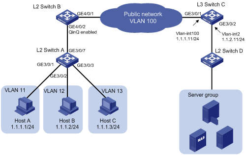
As shown in Figure 6, Host A, Host B, and Host C belong to VLAN 11, VLAN 12, and VLAN 13, respectively. The server group is connected to Switch C. QinQ is enabled on Switch B.
Configure QinQ termination, so that Host A, Host B, and Host C can communicate with the server group.
Configuration procedure
1. Configure Host A, Host B, and Host C:
¡ Configure the IP addresses of Host A, Host B, and Host C as 1.1.1.1/24, 1.1.1.2/24, and 1.1.1.3/24, respectively.
¡ Configure the gateway address as 1.1.1.11/24 for the hosts.
2. Configure Layer 2 Switch A:
# Assign GigabitEthernet 3/0/1 to VLAN 11.
<L2_SwitchA> system-view
[L2_SwitchA] vlan 11
[L2_SwitchA-vlan11] port GigabitEthernet 3/0/1
[L2_SwitchA-vlan11] quit
# Assign GigabitEthernet 3/0/2 to VLAN 12.
[L2_SwitchA] vlan 12
[L2_SwitchA-vlan12] port GigabitEthernet 3/0/2
[L2_SwitchA-vlan12] quit
# Assign GigabitEthernet 3/0/3 to VLAN 13.
[L2_SwitchA] vlan 13
[L2_SwitchA-vlan13] port GigabitEthernet 3/0/3
[L2_SwitchA-vlan13] quit
# Configure GigabitEthernet 3/0/7 as a hybrid port and assign the port to VLANs 11 through 13 as a tagged member.
[L2_SwitchA] interface GigabitEthernet 3/0/7
[L2_SwitchA-GigabitEthernet3/0/7] port link-type hybrid
[L2_SwitchA-GigabitEthernet3/0/7] port hybrid vlan 11 to 13 tagged
3. Configure Layer 2 Switch B:
# Configure GigabitEthernet 4/0/2 as a trunk port, and assign the port to VLAN 100.
<L2_SwitchB> system-view
[L2_SwitchB] interface GigabitEthernet 4/0/2
[L2_SwitchB-GigabitEthernet4/0/2] port link-type trunk
[L2_SwitchB-GigabitEthernet4/0/2] port trunk permit vlan 100
# Configure VLAN 100 as the PVID of GigabitEthernet 4/0/2, enable QinQ on the port to add outer VLAN tag 100 to the received packets.
[L2_SwitchB-GigabitEthernet4/0/2] port trunk pvid vlan 100
[L2_SwitchB-GigabitEthernet4/0/2] qinq enable
[L2_SwitchB-GigabitEthernet4/0/2] quit
# Configure GigabitEthernet 4/0/1 as a trunk port and assign the port to VLAN 100.
[L2_SwitchB] interface GigabitEthernet 4/0/1
[L2_SwitchB-GigabitEthernet4/0/1] port link-type trunk
[L2_SwitchB-GigabitEthernet4/0/1] port trunk permit vlan 100
4. Configure Layer 3 Switch C:
# Create VLAN-interface 100 and assign an IP address to the interface.
<L3_SwitchC> system-view
[L3_SwitchC] vlan 100
[L3_SwitchC-vlan100] quit
[L3_SwitchC] interface vlan-interface 100
[L3_SwitchC-Vlan-interface100] ip address 1.1.1.11 255.255.255.0
# Configure VLAN-interface 100 to remove the outermost two layers of VLAN tags for packets whose outermost VLAN tag is 100, and configure the interface to add inner VLAN tag 11, 12, or 13 to packets before sending them out.
[L3_SwitchC-Vlan-interface100] second-dot1q 11 to 13
[L3_SwitchC-Vlan-interface100] quit
# Configure GigabitEthernet 3/0/1 as a trunk port, and assign the port to VLAN 100.
[L3_SwitchC] interface GigabitEthernet 3/0/1
[L3_SwitchC-GigabitEthernet3/0/1] port link-type trunk
[L3_SwitchC-GigabitEthernet3/0/1] port trunk permit vlan 100
[L3_SwitchC-GigabitEthernet3/0/1] quit
# Create VLAN-interface 2 and assign an IP address to the interface.
[L3_SwitchC] vlan 2
[L3_SwitchC-vlan2] quit
[L3_SwitchC] interface vlan-interface 2
[L3_SwitchC-Vlan-interface2] ip address 1.1.2.11 255.255.255.0
[L3_SwitchC-Vlan-interface2] quit
# Assign GigabitEthernet 3/0/2 to VLAN 2.
[L3_SwitchC] interface GigabitEthernet 3/0/2
[L3_SwitchC-GigabitEthernet3/0/2] port access vlan 2
5. Use the factory configuration of Layer 2 Switch D.
6. Assign each server in the server group an IP address on the network segment 1.1.2.0/24 and configure the gateway IP address as 1.1.2.11/24.
Ambiguous QinQ termination configuration example (lite solution)
In this example, customer network VLANs (CVLANs), also called inner VLANs, refer to the VLANs that a customer uses on the private network. Service provider network VLANs (SVLANs), also called outer VLANs, refer to the VLANs that a service provider uses to carry VLAN tagged traffic for customers.
Network requirements
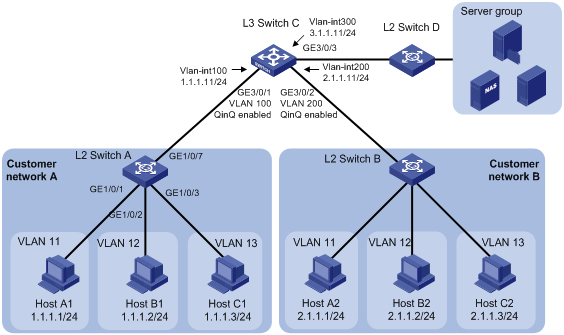
As shown in Figure 7, Layer 3 Switch C is a core network device of a service provider. It connects to Layer 2 Switch A and Layer 2 Switch B through access ports GigabitEthernet 3/0/1 and GigabitEthernet 3/0/2, respectively.
Layer 3 Switch C also connects to a server group through Layer 2 Switch D. Layer 2 Switch D can process only single-tagged VLAN packets.
On customer networks A and B, Host A1 and Host A2 are assigned to CVLAN 11, Host B1 and Host B2 are assigned to CVLAN 12, and Host C2 and Host C2 are assigned to CVLAN 13.
Enable QinQ on GigabitEthernet 3/0/1 and GigabitEthernet 3/0/2 of Layer 3 Switch C to add SVLAN 100 and SVLAN 200 to packets carrying CVLANs 11 through 13 as the outermost VLAN tag, respectively, so the packets are isolated at Layer 2.
Configure QinQ termination on the VLAN interfaces of Layer 3 Switch C to enable all hosts on the customer networks to communicate with the server group and to enable hosts on customer network A to communicate with hosts on customer network B at Layer 3.
Configuration considerations and guidelines
Make sure the number of the current VLAN interface is excluded from the inner VLAN ID range. For example, when you configure the second-dot1q { vlan-list | any } command on VLAN-interface 100, make sure vlan-list does not include 100 and do not use the any keyword.
The following process describes how a packet is transmitted from Host A1 to Host B2:
· Host A1 sends out the packet.
· Layer 2 Switch A adds VLAN 11 to the packet and forwards the single-tagged packet to Layer 3 Switch C.
· Layer 3 Switch C receives the packet on GigabitEthernet 3/0/1, adds VLAN 100 to the packet as the outer VLAN tag, and forwards the double-tagged packet to VLAN-interface 100, which is the gateway of Host A1.
· VLAN-interface 100 removes the two layers of VLAN tags of the packet and forwards the packet to the gateway of Host B2, which is VLAN-interface 200.
· VLAN-interface 200 searches the ARP table for the VLAN ID (VLAN 12) mapped to Host B2, adds outer VLAN tag 200 and inner VLAN tag 12 to the packet, and forwards the double-tagged packet to the access port GigabitEthernet 3/0/2.
· Port GigabitEthernet 3/0/2 removes the default VLAN tag (VLAN 200) of the packet and forwards the packet tagged with VLAN 12 to Layer 2 Switch B.
· Layer 2 Switch B forwards the packet to Host B2 in VLAN 12.
Configuration procedure
1. Configure hosts:
¡ Configure Host A1's IP address as 1.1.1.1/24, Host B1's IP address as 1.1.1.2/24, Host C1's IP address as 1.1.1.3/24, and their gateway IP address as 1.1.1.11/24.
¡ Configure Host A2's IP address as 2.1.1.1/24, Host B2's IP address as 2.1.1.2/24, Host C2's IP address as 2.1.1.3/24, and their gateway IP address as 2.1.1.11/24.
2. Configure Layer 2 Switch A:
# Assign GigabitEthernet 1/0/1 to VLAN 11.
<L2_SwitchA> system-view
[L2_SwitchA] vlan 11
[L2_SwitchA-vlan11] port GigabitEthernet 1/0/1
[L2_SwitchA-vlan11] quit
# Assign GigabitEthernet 1/0/2 to VLAN 12.
[L2_SwitchA] vlan 12
[L2_SwitchA-vlan12] port GigabitEthernet 1/0/2
[L2_SwitchA-vlan12] quit
# Assign GigabitEthernet 1/0/3 to VLAN 13.
[L2_SwitchA] vlan 13
[L2_SwitchA-vlan13] port GigabitEthernet 1/0/3
[L2_SwitchA-vlan13] quit
# Configure GigabitEthernet 1/0/7 as a trunk port and assign the port to VLANs 11 through 13.
[L2_SwitchA] interface GigabitEthernet 1/0/7
[L2_SwitchA-GigabitEthernet1/0/7] port link-type trunk
[L2_SwitchA-GigabitEthernet1/0/7] port trunk permit vlan 11 to 13
3. Configure Layer 2 Switch B in the same way Layer 2 Switch A is configured.
4. Configure Layer 3 Switch C:
# Assign GigabitEthernet 3/0/1 to VLAN 100 and enable QinQ on the interface to tag the received packets with the PVID.
[L3_SwitchC] vlan 100
[L3_SwitchC-vlan100] quit
[L3_SwitchC] interface GigabitEthernet 3/0/1
[L3_SwitchC-GigabitEthernet3/0/1] port access vlan 100
[L3_SwitchC-GigabitEthernet3/0/1] qinq enable
[L3_SwitchC-GigabitEthernet3/0/1] quit
# Create VLAN-interface 100, assign an IP address to the interface, enable QinQ termination on the interface, and specify VLANs 11 through 13 as the inner VLAN tags that can be added to packets.
[L3_SwitchC] interface vlan-interface 100
[L3_SwitchC-Vlan-interface100] ip address 1.1.1.11 255.255.255.0
[L3_SwitchC-Vlan-interface100] second-dot1q 11 to 13
[L3_SwitchC-Vlan-interface100] quit
# Assign GigabitEthernet 3/0/2 to VLAN 200, and enable QinQ on the interface to tag the received packets with the PVID.
[L3_SwitchC] vlan 200
[L3_SwitchC-vlan200] quit
[L3_SwitchC] interface GigabitEthernet 3/0/2
[L3_SwitchC-GigabitEthernet3/0/2] port access vlan 200
[L3_SwitchC-GigabitEthernet3/0/2] qinq enable
[L3_SwitchC-GigabitEthernet3/0/2] quit
# Create VLAN-interface 200, assign an IP address to the interface, enable QinQ termination on the interface, and specify VLANs 11 through 13 as the inner VLAN tags that can be added to packets.
[L3_SwitchC] interface vlan-interface 200
[L3_SwitchC-Vlan-interface200] ip address 2.1.1.11 255.255.255.0
[L3_SwitchC-Vlan-interface200] second-dot1q 11 to 13
[L3_SwitchC-Vlan-interface200] quit
# Assign GigabitEthernet 3/0/3 to VLAN 300.
[L3_SwitchC] vlan 300
[L3_SwitchC-vlan300] interface GigabitEthernet 3/0/3
[L3_SwitchC-vlan300] quit
# Create VLAN-interface 300 and assign an IP address to the interface.
[L3_SwitchC] interface vlan-interface 300
[L3_SwitchC-Vlan-interface300] ip address 3.1.1.11 255.255.255.0
[L3_SwitchC-Vlan-interface300] quit
5. Use the factory configuration of Layer 2 Switch D.
6. Assign each server in the server group an IP address on the network segment 3.1.1.0/24 and configure the gateway IP address as 3.1.1.11/24.
Configuration example for QinQ termination supporting DHCP relay
Network requirements
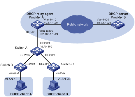
As shown in Figure 8:
· Provider A and Provider B are edge devices on the service provider network.
· DHCP client A and DHCP client B are devices on the customer networks.
· Provider A is the DHCP relay agent and Provider B is the DHCP server.
· Provider A and Provider B communicate with each other through Layer 3 interfaces.
The expected results after the configuration are:
· DHCP relay agent Provider A receives double-tagged packets sent from DHCP clients, terminates these packets by removing their inner and outer VLAN tags, and forwards the packets to DHCP server Provider B through the service provider network.
· DHCP client A and client B can apply for IP addresses and related network configuration parameters from Provider B through the service provider network.
Configuration procedure
1. Configure DHCP relay agent Provider A:
# Enable DHCP service.
<ProviderA> system-view
[ProviderA] dhcp enable
# Create the DHCP server group.
[ProviderA] dhcp relay server-group 1 ip 10.2.1.1
# Create VLAN-interface 100.
[ProviderA] vlan 100
[ProviderA-vlan100] quit
[ProviderA] interface vlan-interface 100
# Enable QinQ termination on the interface and specify VLANs 10 and 20 as the inner VLAN tags that can be added to packets.
[ProviderA-Vlan-interface100] second-dot1q 10 20
# Enable the VLAN interface to transmit broadcast and multicast packets.
[ProviderA-Vlan-interface100] vlan-termination broadcast enable
# Enable DHCP relay on the VLAN interface, select a DHCP server group, and enable address check on the relay agent.
[ProviderA-Vlan-interface100] dhcp select relay
[ProviderA-Vlan-interface100] dhcp relay server-select 1
[ProviderA-Vlan-interface100] dhcp relay address-check enable
# Assign an IP address to the VLAN interface.
[ProviderA-Vlan-interface100] ip address 192.168.1.1 24
[ProviderA-Vlan-interface100] quit
# Configure GigabitEthernet 3/0/1 as a trunk port and assign it to VLAN 100.
[ProviderA] interface GigabitEthernet 3/0/1
[ProviderA-GigabitEthernet3/0/1] port link-type trunk
[ProviderA-GigabitEthernet3/0/1] port trunk permit vlan 100
[ProviderA-GigabitEthernet3/0/1] quit
# Assign an IP address to the interface connecting to the DHCP server.
[ProviderA] interface vlan-interface 10
[ProviderA-Vlan-interface10] ip address 10.1.1.1 24
[ProviderA-Vlan-interface10] quit
# Configure a static route to the DHCP server.
[ProviderA] ip route-static 10.2.1.1 24 10.1.1.1
2. Configure DHCP server Provider B:
# Assign an IP address to the DHCP server.
<ProviderB> system-view
[ProviderB] interface vlan-interface 20
[ProviderB-Vlan-interface20] ip address 10.2.1.1 24
[ProviderB-Vlan-interface20] quit
# Enable DHCP.
[ProviderB] dhcp enable
# Configure an IP address pool on the DHCP server.
[ProviderB] dhcp server ip-pool 1
[ProviderB-dhcp-pool-1] network 192.168.1.0 24
[ProviderB-dhcp-pool-1] gateway-list 192.168.1.1
[ProviderB-dhcp-pool-1] quit
# Configure a static route to VLAN-interface 100.
[ProviderB] ip route-static 192.168.1.1 24 10.1.1.1
3. Configure Switch A:
# Enable QinQ on uplink port GigabitEthernet 2/0/1 and configure it as a trunk port.
<SwitchA> system-view
[SwitchA] interface GigabitEthernet 2/0/1
[SwitchA-GigabitEthernet2/0/1] port link-type trunk
# Assign trunk port GigabitEthernet 2/0/1 to VLAN 100.
[SwitchA-GigabitEthernet2/0/1] port trunk permit vlan 100
[SwitchA-GigabitEthernet2/0/1] quit
# Enable QinQ on downlink port GigabitEthernet 2/0/2.
[SwitchA] interface GigabitEthernet 2/0/2
[SwitchA-GigabitEthernet2/0/2] qinq enable
[SwitchA-GigabitEthernet2/0/2] quit
# Enable QinQ on downlink port GigabitEthernet 2/0/3.
[SwitchA] interface GigabitEthernet 2/0/3
[SwitchA-GigabitEthernet2/0/3] qinq enable
[SwitchA-GigabitEthernet2/0/3] quit
# Assign GigabitEthernet 2/0/2 and GigabitEthernet 2/0/3 to VLAN 100.
[SwitchA] vlan 100
[SwitchA-vlan100] port GigabitEthernet 2/0/2
[SwitchA-vlan100] port GigabitEthernet 2/0/3
4. Configure Switch B:
# Add GigabitEthernet 2/0/2 to VLAN 10.
<SwitchB> system-view
[SwitchB] vlan 10
[SwitchB-vlan10] port GigabitEthernet 2/0/2
[SwitchB-vlan10] quit
# Configure GigabitEthernet 2/0/1 as a trunk port and assign it to VLAN 10.
[SwitchB] interface GigabitEthernet 2/0/1
[SwitchB-GigabitEthernet2/0/1] port link-type trunk
[SwitchB-GigabitEthernet2/0/1] port trunk permit vlan 10
5. Configure Switch C:
# Add GigabitEthernet 2/0/2 to VLAN 20.
<SwitchC> system-view
[SwitchC] vlan 20
[SwitchC-vlan20] port GigabitEthernet 2/0/2
[SwitchC-vlan20] quit
# Configure GigabitEthernet 2/0/1 as a trunk port and assign it to VLAN 20.
[SwitchC] interface GigabitEthernet 2/0/1
[SwitchC-GigabitEthernet2/0/1] port link-type trunk
[SwitchC-GigabitEthernet2/0/1] port trunk permit vlan 20
Verifying the configuration
With the previous configuration, DHCP client A and DHCP client B can obtain their respective IP addresses from the DHCP server. You can view information about the DHCP relay agent bindings on Provider A by using the display dhcp relay security command.