- Table of Contents
-
- 04-Layer 2 - LAN Switching Configuration Guide
- 00-Preface
- 01-VLAN Configuration
- 02-MAC Address Table Configuration
- 03-Spanning Tree Configuration
- 04-Ethernet Link Aggregation Configuration
- 05-Port Isolation Configuration
- 06-QinQ Configuration
- 07-VLAN Mapping Configuration
- 08-BPDU Tunneling Configuration
- 09-GVRP Configuration
- 10-Loopback Detection Configuration
- 11-VLAN Termination Configuration
- 12-MAC-in-MAC Configuration
- 13-LLDP Configuration
- 14-MVRP Configuration
- Related Documents
-
| Title | Size | Download |
|---|---|---|
| 10-Loopback Detection Configuration | 115.96 KB |
Contents
Configuring loopback detection
Basic concepts in loopback detection
Loopback detection configuration task list
Enabling loopback detection in system view
Enabling loopback detection in VLAN view
Configuring the loopback detection action
Configuring the loopback detection interval
Displaying and maintaining loopback detection
Loopback detection configuration example
Overview
Basic concepts in loopback detection
Loopback detection frame
The switch detects loops by sending loopback detection frames and then checking whether or not these frames return (not necessarily to the sending ports). If a port on the switch receives a loopback detection frame sent by the switch, the port is considered looped.
Loopback detection is usually VLAN based; however, incorrect QinQ or VLAN mapping configurations might also cause loops. Even though the VLAN information carried in loopback detection frames returned to the switch is changed, the switch still considers the receiving ports looped. For more information about QinQ and VLAN switching, see "Configuring QinQ" and "Configuring VLAN mapping."
Figure 1 Ethernet header of a loopback detection frame
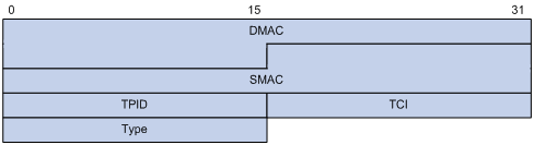
Figure 1 shows the format of the Ethernet header of a loopback detection frame. The Ethernet header contains the following fields:
· DMAC—Destination MAC address of the loopback detection frame, which is the multicast MAC address 010F-E200-0007. When a loopback detection-enabled switch receives a frame with this destination MAC address, it sends the frame to the CPU and broadcasts the frame in the VLAN from which the frame was originally received.
· SMAC—Source MAC address of the loopback detection frame, which is the bridge MAC address of the sending switch.
· TPID—Tag Protocol Identifier, type of the VLAN tag, with the value of 0x8100.
· TCI—Tag Control Information, information of the VLAN tag, including the priority and VLAN ID.
· Type—Protocol type, with the value of 0x8918.
Figure 2 Inner header of a loopback detection frame
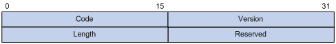
Figure 2 shows the format of the inner header of a loopback detection frame. The inner header contains the following fields:
· Code—Protocol sub-type, with the value of 0x0001, indicating the loopback detection protocol.
· Version—Protocol version, with the value of 0x0000, which is reserved.
· Length—Length of the loopback detection frame, including the inner header, but not the Ethernet header.
· Reserved—This field is reserved.
Loopback detection frames are constructed in the form of TLV (type/length/value) triplets. Table 1 lists the required and optional TLVs supported by the loopback detection mechanism.
Table 1 TLVs supported by the loopback detection mechanism
|
TLV |
Description |
Remarks |
|
End of PDU |
TLV that indicates the end of a PDU. |
Optional. |
|
Device ID |
TLV that indicates the bridge MAC address of the sending switch. |
Required. |
|
Port ID |
TLV that indicates the ID of the PDU sending port. |
Optional. |
|
Port Name |
TLV that indicates the name of the PDU sending port. |
Optional. |
|
System Name |
TLV that indicates the switch name. |
Optional. |
|
Chassis ID |
TLV that indicates the chassis ID of the sending port. |
Optional. |
|
Slot ID |
TLV that indicates the slot ID of the sending port. |
Optional. |
Loopback detection interval
How loopback detection works
Loopback detection actions
Loopback detection actions refer to the actions taken by the system when detecting loops. The following actions are available:
· None—When detecting a looped port, the system takes no action on the port except printing log information and sending trap messages. If no loopback detection frames are received within three loopback detection intervals, the system determines that the loop is already removed, and again prints log information to notify the user.
· Shutdown—When detecting a looped port, besides printing log information and sending trap messages, the system also shuts down the port to disable it from receiving and sending frames (including loopback detection frames). After the port status detection timer (set by the shutdown-interval command) expires, the system will bring up the port. For more information about the port status detection timer, see Fundamentals Configuration Guide.
Loop status auto recovery
After the switch detects a loop on a port, the switch continues to monitor the loopback detection frames. If no loopback detection frame is received within three times the loopback detection interval, the switch concludes that the loop is removed and notifies the users of this event. This process is known as loop status auto recovery.
Loop status auto recovery applies only when the loopback detection action is none. When the loopback detection action is shutdown, the switch automatically shuts down looped ports and thus removes the loop. After the port status detection timer (set by the shutdown-interval command) expires, the system will bring up the port. If the loop still exists, the system shuts down the port again.
When a network loop occurs, the switch discards some of the frames to reduce the load. If the loopback detection frames are among the discarded frames, the loop status auto recovery function on the switch will erroneously conclude that the loop has already been removed. To avoid this, set the loopback detection action to shutdown, or manually remove the loop when the switch reports the occurrence of the loop if you set the loopback detection action to none.
Loopback detection configuration task list
|
Task |
Remarks |
|
Required. |
|
|
Optional. |
|
|
Optional. |
Enabling loopback detection
You can enable the loopback detection function in system view or VLAN view. After you enable loopback detection for a VLAN, the system performs loopback detection on all the ports in the VLAN.
Enabling loopback detection in system view
In system view, you can bulk enable loopback detection for multiple or all VLANs.
To enable loopback detection in system view:
|
Step |
Command |
Remarks |
|
1. Enter system view. |
system-view |
N/A |
|
2. Enable loopback detection. |
loopback-detection enable vlan { vlan-list | all } |
By default, this function is disabled. |
Enabling loopback detection in VLAN view
In VLAN view, you can enable loopback detection only for the current VLAN.
To enable loopback detection in VLAN view:
|
Step |
Command |
Remarks |
|
1. Enter system view. |
system-view |
N/A |
|
2. Enter VLAN view. |
vlan vlan-id |
N/A |
|
3. Enable loopback detection. |
loopback-detection enable |
By default, this function is disabled. |
|
|
NOTE: H3C recommends not configuring the port mirroring function on the member ports of a loopback detection-enabled VLAN. For more information about port mirroring, see Network Management and Monitoring Configuration Guide. |
Configuring the loopback detection action
You can set the loopback detection action to none or shutdown.
To set the loopback detection action:
|
Step |
Command |
Remarks |
|
1. Enter system view. |
system-view |
N/A |
|
2. Configure the loopback detection action. |
loopback-detection action { none | shutdown } |
By default, the loopback detection action is none. |
Configuring the loopback detection interval
With loopback detection enabled, the switch sends loopback detection frames at a specified interval. The shorter this interval is, the faster the system can detect loops, but the more system resources will be used. You must consider both the system performance and loopback detection speed for choosing a correct interval.
To configure the loopback detection interval:
|
Step |
Command |
Remarks |
|
1. Enter system view. |
system-view |
N/A |
|
2. Configure the loopback detection interval. |
loopback-detection interval-time interval |
The default setting is 30 seconds. |
Displaying and maintaining loopback detection
|
Task |
Command |
Remarks |
|
Display the status of loopback detection. |
display loopback-detection [ | { begin | exclude | include } regular-expression ] |
Available in any view. |
Loopback detection configuration example
By default, Ethernet, VLAN, and aggregate interfaces are in DOWN state. Before configuring these interfaces, use the undo shutdown command to bring them up.
Network requirements
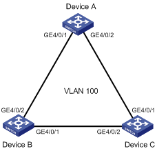
As shown in Figure 3, the network administrator typically shuts down GigabitEthernet 4/0/1 of Device B to prevent loops in the network.
Configure loopback detection on Device A so that when a loop resulting from incorrect configuration occurs, Device A can automatically shut down the looped port and remind the user to check the network connections by printing log information and sending trap messages.
Configuration procedure
Configuring Device A
# Create VLAN 100, and then enable loopback detection on it.
<DeviceA> system-view
[DeviceA] vlan 100
[DeviceA-vlan100] loopback-detection enable
[DeviceA–vlan100] quit
# Configure GigabitEthernet 4/0/1 and GigabitEthernet 4/0/2 as trunk ports, and assign the ports to VLAN 100.
[DeviceA] interface GigabitEthernet 4/0/1
[DeviceA-GigabitEthernet4/0/1] port link-type trunk
[DeviceA-GigabitEthernet4/0/1] port trunk permit vlan 100
[DeviceA-GigabitEthernet4/0/1] quit
[DeviceA] interface GigabitEthernet 4/0/2
[DeviceA-GigabitEthernet4/0/2] port link-type trunk
[DeviceA-GigabitEthernet4/0/2] port trunk permit vlan 100
[DeviceA-GigabitEthernet4/0/2] quit
# Set the loopback detection action to shutdown.
[DeviceA] loopback-detection action shutdown
# Set the loopback detection interval to 35 seconds.
[DeviceA] loopback-detection interval-time 35
Configuring Device B
# Create VLAN 100.
<DeviceB> system-view
[DeviceB] vlan 100
[DeviceB–vlan100] quit
# Configure GigabitEthernet 4/0/1 and GigabitEthernet 4/0/2 as trunk ports, and assign the ports to VLAN 100.
[DeviceB] interface GigabitEthernet 4/0/1
[DeviceB-GigabitEthernet4/0/1] port link-type trunk
[DeviceB-GigabitEthernet4/0/1] port trunk permit vlan 100
[DeviceB-GigabitEthernet4/0/1] quit
[DeviceB] interface GigabitEthernet 4/0/2
[DeviceB-GigabitEthernet4/0/2] port link-type trunk
[DeviceB-GigabitEthernet4/0/2] port trunk permit vlan 100
[DeviceB-GigabitEthernet4/0/2] quit
# Shut down GigabitEthernet 4/0/1 to prevent loops.
[DeviceB] interface GigabitEthernet 4/0/1
[DeviceB-GigabitEthernet4/0/1] shutdown
[DeviceB-GigabitEthernet4/0/1] quit
Configuring Device C
# Create VLAN 100.
<DeviceC> system-view
[DeviceC] vlan 100
[DeviceC–vlan100] quit
# Configure GigabitEthernet 4/0/1 and GigabitEthernet 4/0/2 as trunk ports, and assign the ports to VLAN 100.
[DeviceB] interface GigabitEthernet 4/0/1
[DeviceB-GigabitEthernet4/0/1] port link-type trunk
[DeviceB-GigabitEthernet4/0/1] port trunk permit vlan 100
[DeviceB-GigabitEthernet4/0/1] quit
[DeviceB] interface GigabitEthernet 4/0/2
[DeviceB-GigabitEthernet4/0/2] port link-type trunk
[DeviceB-GigabitEthernet4/0/2] port trunk permit vlan 100
[DeviceB-GigabitEthernet4/0/2] quit
Verifying the configuration
Use the display loopback-detection command to check the status of loopback detection on each device.
# Display the loopback detection status on Device A.
[DeviceA] display loopback-detection
Loopback-detection is running.
Detection interval is 30 second(s).
Action mode: Shutdown
Loopback-detection is enabled on the following VLAN(s):
100
No loopback is detected on any interface.
The output shows that loopback detection is enabled on Device A, and no looped ports are detected.
# Display the loopback detection status on Device B.
[DeviceB] display loopback-detection
Loopback-detection is not running.
# Display the loopback detection status on Device C.
[DeviceC] display loopback-detection
Loopback-detection is not running.
The output shows that loopback detection is not enabled on Device B or Device C.
GigabitEthernet 4/0/1 of Device B is brought up by the network administrator by mistake. Within a loopback detection interval, Device A will detect a loop on ports GigabitEthernet 4/0/1 and GigabitEthernet 4/0/2. Consequently, it automatically shuts down the ports and prints the following log information:
[DeviceA]
%Feb 24 15:04:29:663 2013 DeviceA LPDT/4/LOOPED:Slot=4;
Loopback exists on GigabitEthernet4/0/1 in VLAN 100.
%Feb 24 15:04:29:667 2013 DeviceA LPDT/4/LOOPED:Slot=1;
Loopback exists on GigabitEthernet4/0/2 in VLAN 100.
%Feb 24 15:04:44:243 2013 DeviceA LPDT/4/RECOVERED:Slot=4;
Loopback on GigabitEthernet4/0/1 recovered.
%Feb 24 15:04:44:248 2013 DeviceA LPDT/4/RECOVERED:Slot=1;
Loopback on GigabitEthernet4/0/2 recovered.
When you see the log information above, use the display loopback-detection command again to display the loopback detection status on Device A.
# Display the loopback detection operating status on Device A.
[DeviceA] display loopback-detection
Loopback-detection is running.
Detection interval is 35 second(s).
Action mode: Shutdown
Loopback-detection is enabled on the following VLAN(s):
100
No loopback is detected on any interface.
The output shows that no loop is detected on GigabitEthernet 4/0/1 and GigabitEthernet 4/0/2. The reason is that the loopback detection action is set to shutdown, in which case, the two ports are automatically shut down when a loop occurs on them. The shutdown action removes the loop. Use the display interface command to display the status information of GigabitEthernet 4/0/1 and GigabitEthernet 4/0/2 on Device A:
# Display the status information of GigabitEthernet 4/0/1 on Device A.
[DeviceA] display interface gigabitethernet 4/0/1
GigabitEthernet 4/0/1 current state: DOWN ( Loopback detection-protected )
...
# Display the status information of GigabitEthernet 4/0/2 on Device A.
[DeviceA] display interface gigabitethernet 4/0/2
GigabitEthernet 4/0/2 current state: DOWN ( Loopback detection-protected )
...
The output above shows that GigabitEthernet 4/0/1 and GigabitEthernet 4/0/2 have already been shut down by the loopback detection module.