- Table of Contents
-
- 01-Fundamentals Configuration Guide
- 00-Preface
- 01-CLI Configuration
- 02-Login Management Configuration
- 03-FTP and TFTP Configuration
- 04-File System Management
- 05-Configuration File Management Configuration
- 06-Software Upgrade Configuration
- 07-ISSU Configuration
- 08-Device Management Configuration
- 09-Automatic Configuration
- 10-Management with BootWare
- Related Documents
-
| Title | Size | Download |
|---|---|---|
| 08-Device Management Configuration | 247.26 KB |
Contents
Enabling displaying the copyright statement
Configuring the exception handling method
Configuring the system operating mode
Scheduling a job by using the non-modular method
Scheduling a job by using the modular method
Scheduled job configuration example
Configuring the port status detection timer
Enabling power supply management
Powering on and powering off a card·
Allocating IDs for AC power supplies
Configuring temperature thresholds for a card
Isolating and diagnosing a card
Configuring in-service hardware failure diagnosis and failure protection
Configuring the size of shared buffers on an interface card
Clearing unused 16-bit interface indexes
Enabling automatic forwarding path check
Enabling port recovery for the switch
Verifying and diagnosing transceiver modules
Diagnosing transceiver modules
Displaying and maintaining device management
Device management includes monitoring the operating status of devices and configuring their running parameters.
Storage media include Flash, compact Flash (CF), and universal serial bus (USB). Flash is exemplified in this document.
The configuration tasks in this document are all optional and independent from one another.
Configuring the device name
A device name identifies a device in a network and works as the user view prompt at the CLI. For example, if the device name is Sysname, the user view prompt is <Sysname>.
To configure the device name:
|
Step |
Command |
Remarks |
|
1. Enter system view. |
system-view |
N/A |
|
2. Configure the device name. |
sysname sysname |
Optional. By default, the device name is H3C. |
Changing the system time
You must synchronize your device with a trusted time source by using NTP or changing the system time before you run it on the network. Network management depends on an accurate system time setting, because the timestamps of system messages and logs use the system time.
In a small-sized network, you can manually set the system time of each device.
Configuration guidelines
You can change the system time by configuring the relative time, time zone, and daylight saving time. The configuration result depends on their configuration order (see Table 1). In the first column of this table, 1 represents the clock datetime command, 2 represents the clock timezone command, and 3 represents the clock summer-time command. To verify the system time setting, use the display clock command. This table assumes that the original system time is 2005/1/1 1:00:00.
Table 1 System time configuration results
|
Command |
Effective system time |
Configuration example |
System time |
|
1 |
date-time |
01:00:00 UTC Mon 01/01/2007. |
|
|
2 |
Original system time ± zone-offset |
02:00:00 zone-time Sat 01/01/2005. |
|
|
1, 2 |
date-time ± zone-offset |
03:00:00 zone-time Fri 02/02/2007. |
|
|
2, 1 |
date-time |
03:00:00 zone-time Sat 03/03/2007. |
|
|
3 |
The original system time outside the daylight saving time range: The system time does not change until it is in the daylight saving time range. |
01:00:00 UTC Sat 01/01/2005. |
|
|
The original system time in the daylight saving time range: The system time increases by summer-offset. |
03:00:00 ss Sat 01/01/2005. NOTE: If the original system time plus summer-offset is beyond the daylight saving time range, the original system time does not change. After you disable the daylight saving setting, the system time automatically decreases by summer-offset. |
||
|
1, 3 |
date-time outside the daylight saving time range: date-time |
01:00:00 UTC Mon 01/01/2007. |
|
|
date-time in the daylight saving time range: date-time + summer-offset |
10:00:00 ss Mon 01/01/2007. NOTE: If the date-time plus summer-offset is outside the daylight saving time range, the system time equals date-time. After you disable the daylight saving setting, the system time automatically decreases by summer-offset. |
||
|
3, 1 (date-time outside the daylight saving time range) |
date-time |
01:00:00 UTC Tue 01/01/2008. |
|
|
3, 1 (date-time in the daylight saving time range) |
date-time – summer-offset outside the daylight saving time range: date-time – summer-offset |
23:30:00 UTC Sun 12/31/2006. |
|
|
date-time – summer-offset in the daylight saving time range: date-time |
03:00:00 ss Mon 01/01/2007. |
||
|
2, 3 or 3, 2 |
Original system clock ± zone-offset outside the daylight saving time range: Original system clock ± zone-offset |
02:00:00 zone-time Sat 01/01/2005. |
|
|
Original system clock ± zone-offset outside the daylight saving time range: Original system clock ± zone-offset + summer-offset |
System clock configured: 04:00:00 ss Sat 01/01/2005. |
||
|
1, 2 , 3 or 1, 3, 2 |
date-time ± zone-offset outside the daylight saving time range: date-time ± zone-offset |
02:00:00 zone-time Mon 01/01/2007. |
|
|
date-time ± zone-offset outside the daylight saving time range: date-time ± zone-offset + summer-offset |
04:00:00 ss Mon 01/01/2007. |
||
|
2, 3, 1 or 3, 2, 1 |
date-time outside the daylight saving time range: date-time |
01:00:00 zone-time Mon 01/01/2007. |
|
|
date-time in the daylight saving time range, but date-time – summer-offset outside the summer-time range: date-time – summer-offset |
23:30:00 zone-time Mon 12/31/2007. |
||
|
Both date-time and date-time – summer-offset in the daylight saving time range: date-time |
03:00:00 ss Tue 01/01/2008. |
Configuration procedure
To change the system time:
|
Step |
Command |
Remarks |
|
1. Set the time and date. |
clock datetime time date |
Optional. Available in user view. |
|
2. Enter system view. |
system-view |
N/A |
|
3. Set the time zone. |
clock timezone zone-name { add | minus } zone-offset |
Optional. Universal time coordinated (UTC) time zone by default. |
|
4. Set a daylight saving time scheme. |
· Set a non-recurring scheme: · Set a recurring scheme: |
Optional. Use either command. By default, daylight saving time is disabled, and the UTC time zone applies. |
Enabling displaying the copyright statement
The device by default displays the copyright statement when a Telnet or SSH user logs in, or when a console user quits user view. You can disable or enable the function as needed. The following is a sample copyright statement:
**************************************************************************
* Copyright (c) 2004-2011 Hangzhou H3C Tech. Co., Ltd. All rights reserved.*
* Without the owner's prior written consent, *
* no decompiling or reverse-engineering shall be allowed. * **************************************************************************
To enable displaying the copyright statement:
|
Step |
Command |
Remarks |
|
1. Enter system view. |
system-view |
N/A |
|
2. Enable displaying the copyright statement. |
copyright-info enable |
Optional. Enabled by default. |
Configuring banners
Banners are messages that the system displays during user login.
The system supports the following banners:
· Legal banner—Appears after the copyright or license statement. To continue login, the user must enter Y or press Enter. To quit the process, the user must enter N. Y and N are case-insensitive.
· Message of the Day (MOTD) banner—Appears after the legal banner and before the login banner.
· Login banner—Appears only when password or scheme authentication has been configured.
· Incoming banner—Appears for Modem users.
· Shell banner—Appears for non-Modem users.
Banner input modes
You can configure a single-line banner or a multi-line banner:
· Single-line banner.
A single-line banner must be input in the same line as the command. The start and end delimiters for the banner can be any printable character, but they must be the same and must not be included in the banner. The input text, including the command keywords and the delimiters, cannot exceed 510 characters. Do not press Enter before you input the end delimiter.
For example, you can configure the shell banner "Have a nice day." as follows:
<System> system-view
[System] header shell %Have a nice day.%
· Multi-line banner.
A multi-line banner can be up to 2000 characters. To input a multi-line banner, use one of the following methods:
¡ Method 1—Press Enter after the final command keyword. At the system prompt, enter the banner message and end with the delimiter character %. For example, you can configure the banner “Have a nice day. Please input the password.” as follows:
<System> system-view
[System] header shell
Please input banner content, and quit with the character '%'.
Have a nice day.
Please input the password.%
¡ Method 2—After you type the final command keyword, type any character as the start delimiter for the banner message and press Enter. At the system prompt, type the banner message and end the final line with a delimiter that is the same as the start delimiter. For example, you can configure the banner “Have a nice day. Please input the password.” as follows:
<System> system-view
[System] header shell A
Please input banner content, and quit with the character 'A'.
Have a nice day.
Please input the password.A
¡ Method 3—After you type the final keyword, type the start delimiter and part of the banner message and press Enter. At the system prompt, enter the rest of the banner and end the final line with a delimiter that is the same as the start delimiter. Using this method, you can use any character as the start and end delimiters but must make sure that it is not the same as the end character of the message text in the first line. For example, you can configure the banner “Have a nice day. Please input the password.” as follows:
<System> system-view
[System] header shell AHave a nice day.
Please input banner content, and quit with the character 'A'.
Please input the password.A
Configuration procedure
To configure a banner:
|
Step |
Command |
Remarks |
|
1. Enter system view. |
system-view |
N/A |
|
2. Configure the incoming banner. |
header incoming text |
Optional. |
|
3. Configure the login banner. |
header login text |
Optional. |
|
4. Configure the legal banner. |
header legal text |
Optional. |
|
5. Configure the shell banner. |
header shell text |
Optional. |
|
6. Configure the MOTD banner. |
header motd text |
Optional. |
Configuring the exception handling method
In standalone mode, when the system detects any software abnormality on the active main processing unit (MPU), it handles the situation with one of the following methods:
· reboot—The device automatically reboots the failed active MPU to recover from the error condition.
· maintain—The device stays in the error condition so you can collect complete data, including error messages, for diagnosis. Using this method, you must manually reboot the device.
The system always reboots a card or the auxiliary CPU system when an exception occurs to them.
To configure the exception handling method:
|
Step |
Command |
Remarks |
|
1. Enter system view. |
system-view |
N/A |
|
2. Configure the exception handling method of the MPUs. |
system-failure { maintain | reboot } |
Optional. By default, an MPU reboots when an exception occurs to it. |
In IRF mode, when the system detects any software abnormality on the active MPU on an IRF member device, it handles the situation with one of the following two methods:
· reboot—The device automatically reboots the failed active MPU to recover from the error condition.
· maintain—The device stays in the error condition so you can collect complete data, including error messages, for diagnosis. Using this method, you must manually reboot the device.
The system always reboots a card or the auxiliary CPU system when an exception occurs to them.
The exception handling method is effective only for the failed card, and does not influence the functions of other cards or the IRF fabric.
To configure the exception handling method:
|
Step |
Command |
Remarks |
|
1. Enter system view. |
system-view |
N/A |
|
2. Configure the exception handling method of the MPUs. |
system-failure { maintain | reboot } |
By default, an MPU reboots when an exception occurs to it. |
Rebooting the switch
|
|
CAUTION: Device reboot can interrupt network services. |
You can reboot the switch in one of the following ways to recover from an error condition:
· Reboot the switch immediately at the CLI.
· At the CLI, schedule a reboot to occur at a specific time and date or after a delay.
· Power off and then re-power on the switch. This method might cause data loss and hardware damage, and is the least preferred method.
Reboot at the CLI enables easy remote device maintenance.
Configuration guidelines
· To avoid data loss, use the save command to save the current configuration before a reboot.
· Use the display startup and display boot-loader commands to check that you have correctly set the startup configuration file and the main system software image file. If the main system software image file has been corrupted or does not exist, the device cannot reboot. You must re-specify a main system software image file, or power off the device and then power it on so the system can reboot with the backup system software image file.
· If the switch has only one MPU, rebooting the MPU causes the device to reboot. If the switch has two MPUs, rebooting the active MPU causes the active MPU to reboot and an active/standby switchover. You cannot use the reboot command to reboots a standby MPU. To reboot a standby MPU, use the slave restart command (see High Availability Command Reference).
Configuration procedure
To reboot a switch, perform one of these commands in user view:
|
Task |
Command |
Remarks |
|
Reboot a switch. |
· Reboot a card, or the whole system immediately
(in standalone mode):
· Reboot a card, a member switch, or the whole
system immediately (in IRF mode): |
Use either command. |
To schedule a device reboot, perform one of the following commands in user view:
|
Task |
Command |
Remarks |
|
Schedule a reboot. |
· Schedule a reboot to occur at a specific time
and date: · Schedule a reboot to occur after a delay: |
Use either command. The scheduled reboot function is disabled by default. NOTE: Changing any clock setting can cancel the reboot schedule. |
For data security, if you are performing file operations at the reboot time, the system does not reboot.
Configuring the system operating mode
With different system operating modes, the system adjusts the hardware resources to meet the requirements of different services. The switch has the following system operating modes:
· advance—Advanced mode
· bridgee—Enhanced L2 mode
· routee—Enhanced L3 mode
· standard—Standard mode
H3C recommends that you restart the switch immediately to make this configuration take effect.
To configure the system operating mode:
|
Step |
Command |
Remarks |
|
1. Enter system view. |
system-view |
N/A |
|
2. Configure the system operating mode. |
system working mode { advance | bridgee | routee | standard } |
By default, the system operating mode is standard. |
Support for the system operating modes depends on the card type. The following table illustrates the correspondence.
|
System operating mode |
EB card |
EC card |
EF card |
OAA card |
|
standard |
Supported |
Supported |
Supported |
Supported |
|
bridgee |
Not supported |
Supported |
Supported |
Supported |
|
routee |
Not supported |
Supported |
Supported |
Supported |
|
advance |
Not supported |
Not supported |
Supported |
Not supported |
An EB card has a silkscreen ended with EB, for example, LST1GT48LEB1. An EC or EF card has a silkscreen ended with EC or EF.
The default parameters of some commands vary with system operating modes. Those parameters that do not vary with different system operating modes are not listed in the table. The following table illustrates the details.
|
Command |
Argument |
Operating mode and default value |
|||
|
Standard |
Bridgee |
Routee |
Advance |
||
|
multicast-vlan ipv6 entry-limit limit |
limit |
511 |
4095 |
4095 |
4095 |
|
multicast-vlan entry-limit limit |
limit |
2047 |
4096 |
16384 |
30720 |
|
mac-table limit mac-limit-num |
mac-limit-num |
Not supported |
131072 |
65536 |
131072 |
|
multicast forwarding-table route-limit limit |
limit |
2047 |
4096 |
16384 |
30720 |
|
mld group-limit limit |
limit |
2048 |
8192 |
8192 |
8192 |
|
ip verify source max-entries number |
number |
1536 |
7680 (without the acl ipv6 enable command configured) 3584 (with the acl ipv6 enable command configured) |
7680 (without the acl ipv6 enable command configured) 3584 (with the acl ipv6 enable command configured) |
32256 (without the acl ipv6 enable command configured) 15872 (with the acl ipv6 enable command configured) |
|
number |
1536 |
3584 |
3584 |
15872 |
|
Scheduling jobs
You can schedule a job to automatically run a command or a set of commands without administrative interference. The commands in a job are polled every minute. When the scheduled time for a command is reached, the job automatically executes the command. If a confirmation is required while the command is running, the system automatically enters Y or Yes. If characters are required, the system automatically enters a default character string or an empty character string when no default character string is available.
Job configuration methods
You can configure jobs using a non-modular or modular method. Use the non-modular method for a one-time command execution and use non-modular method for complex maintenance work.
Table 2 A comparison of non-modular and modular methods
|
Comparison item |
||
|
Configuration method |
Configure all elements in one command. |
Separate job, view, and time settings. |
|
Can multiple scheduled jobs be configured? |
No. |
Yes. |
|
Can a job contain multiple commands? |
No. If you use the schedule job command multiple times, the most recent configuration takes effect. |
Yes. You can use the time command in job view to configure commands to be executed at different time points. |
|
Supported views |
User view and system view. In the schedule job command, shell represents user view, and system represents system view. |
All views. In the time command, monitor represents user view. |
|
Supported commands |
Commands in user view and system view. |
Commands in all views. |
|
Can a job be repeatedly executed? |
No. |
Yes. |
|
Can a job be saved? |
No. |
Yes. |
|
Can a job be backed up to the standby MPUs? |
No. |
Yes. |
Configuration guidelines
· To have a job successfully run a command, check that the specified view and command are valid. The system does not verify their validity.
· The configuration interface, view, and user status that you have before job execution restores even if the job has run a command that changes the user interface (for example, telnet, ftp, and ssh2), the view (for example, system-view and quit), or the user status (for example, super).
· The jobs run in the background without displaying any messages except log, trap and debugging messages.
· Using the modular method:
¡ Every job can have only one view and up to 10 commands. If you specify multiple views, the view specified most recently takes effect.
¡ Input a view name in its complete form. Most commonly used view names include monitor for user view, system for system view, GigabitEthernet x/x/x for Ethernet interface view, and Vlan-interfacex for VLAN interface view.
¡ The time ID (time-id) must be unique in a job. If two time and command bindings have the same time ID, the binding configured most recently takes effect.
Scheduling a job by using the non-modular method
To schedule a job, perform one of the following commands in user view:
|
Task |
Command |
Remarks |
|
Schedule a job. |
· Schedule a job to run a command at a specific time: · Schedule a job to run a command after a delay: |
Use either command. NOTE: · If you execute the schedule job command multiple times, the most recent configuration takes effect. · Changing any clock setting can cancel the job set by using the schedule job command. |
Scheduling a job by using the modular method
|
Step |
Command |
Remarks |
|
1. Enter system view. |
system-view |
N/A |
|
2. Create a job and enter job view. |
job job-name |
N/A |
|
3. Specify the view in which the commands in the job run. |
view view-name |
You can specify only one view for a job. The job executes all commands in the specified view. |
|
4. Add commands to the job. |
· Configure a command to run at a specific time and date: · Configure a command to run at a specific time: · Configure a command to run after a delay: |
Use any of the commands. NOTE: Changing a clock setting does not affect the schedule set by using the time at or time delay command. |
Scheduled job configuration example
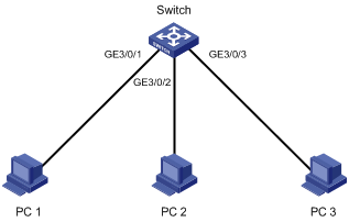
Network requirements
Configure scheduled jobs on the device to enable interfaces GigabitEthernet 3/0/1, GigabitEthernet 3/0/2, and GigabitEthernet 3/0/3 at 8:00 and disabled them at 18:00 on working days every week, to control the access of the PCs connected to these interfaces.
Figure 1 Network diagram
Configuration procedure
# Enter system view.
<Sysname> system-view
# Create scheduled job pc1, and enter its view.
[Sysname] job pc1
# Configure the job to be executed in the view of GigabitEthernet 3/0/1.
[Sysname-job-pc1] view GigabitEthernet 3/0/1
# Configure the device to start GigabitEthernet 3/0/1 at 8:00 on working days every week.
[Sysname-job-pc1] time 1 repeating at 8:00 week-day mon tue wed thu fri command undo shutdown
# Configure the device to shut down GigabitEthernet 3/0/1 at 18:00 on working days every week.
[Sysname-job-pc1] time 2 repeating at 18:00 week-day mon tue wed thu fri command shutdown
[Sysname-job-pc1] quit
# Create scheduled job pc2, and enter its view.
[Sysname] job pc2
# Configure the job to be executed in the view of GigabitEthernet 3/0/2.
[Sysname-job-pc2] view GigabitEthernet 3/0/2
# Configure the device to start GigabitEthernet 3/0/2 at 8:00 on working days every week.
[Sysname-job-pc2] time 1 repeating at 8:00 week-day mon tue wed thu fri command undo shutdown
# Configure the device to shut down GigabitEthernet 3/0/2 at 18:00 on working days every week.
[Sysname-job-pc2] time 2 repeating at 18:00 week-day mon tue wed thu fri command shutdown
[Sysname-job-pc2] quit
# Create scheduled job pc3, and enter its view.
[Sysname] job pc3
# Configure the job to be executed in the view of GigabitEthernet 3/0/3.
[Sysname-job-pc3] view GigabitEthernet 3/0/3
# Configure the device to start GigabitEthernet 3/0/3 at 8:00 on working days every week.
[Sysname-job-pc3] time 1 repeating at 8:00 week-day mon tue wed thu fri command undo shutdown
# Configure the device to shut down GigabitEthernet 3/0/3 at 18:00 on working days every week.
[Sysname-job-pc3] time 2 repeating at 18:00 week-day mon tue wed thu fri command shutdown
[Sysname-job-pc3] quit
# Display information about scheduled jobs.
[Sysname] display job
Job name: pc1
Specified view: GigabitEthernet3/0/1
Time 1: Execute command undo shutdown at 08:00 Mondays Tuesdays Wednesdays Thursdays Fridays
Time 2: Execute command shutdown at 18:00 Mondays Tuesdays Wednesdays Thursdays Fridays
Job name: pc2
Specified view: GigabitEthernet3/0/2
Time 1: Execute command undo shutdown at 08:00 Mondays Tuesdays Wednesdays Thursdays Fridays
Time 2: Execute command shutdown at 18:00 Mondays Tuesdays Wednesdays Thursdays Fridays
Job name: pc3
Specified view: GigabitEthernet3/0/3
Time 1: Execute command undo shutdown at 08:00 Mondays Tuesdays Wednesdays Thursdays Fridays
Time 2: Execute command shutdown at 18:00 Mondays Tuesdays Wednesdays Thursdays Fridays
Configuring the port status detection timer
Some protocols might shut down ports under specific circumstances. For example, MSTP shuts down a BPDU guard-enabled port when the port receives a BPDU, and the loop detection function in shutdown mode shuts down a port when a loop is detected on the port. You can set the port status detection timer so the device restores the port to its original physical status if the port is still down when the timer expires.
To configure the port status detection timer:
|
Step |
Command |
Remarks |
|
1. Enter system view. |
system-view |
N/A |
|
2. Configure the port status detection timer. |
shutdown-interval time |
Optional. 30 seconds by default. |
Managing power supplies
This section describes how to manage power supplies.
|
|
IMPORTANT: After you remove a power supply, wait 30 seconds before installing it again. Otherwise, the power supply might fail. |
Enabling power supply management
With the power supply management function, the system monitors the available power and system loads in real time. When the power module is about to be overloaded, and before hardware protection is performed, the system takes protective measures, for example, sending a message or limiting power supply to the interface cards. Power supply management applies to the following scenarios:
· When you insert an interface card, if power supply management is not enabled, the system directly provides power supply to the card. This might result in insufficient power supply and the system stops power supply to the entire frame. If power supply management is enabled, the system compares the maximum power consumption of the inserted interface card with the system available power. If the former is not greater than the latter, the system provides power supply to the interface card. Otherwise, the system uses the redundant power supplies. If the system still cannot provide enough power, the system does not provide power supply to the interface card.
· When the power supply is insufficient because a power supply fails or is removed, if power supply management is not enabled, the system performs self hardware protection. If power supply management is enabled, the system starts the redundant power supplies. If no redundant power supply is available, the system starts self hardware protection.
Redundant power supplies are reserved for power supply backup. For example, if you insert three power supplies, you can set one of them as a redundant power supply. With power supply management, the system starts a redundant power supply automatically when a power supply fails or is removed, or when power consumption increases. Use the display power-supply command to view the power supply of the device.
If power supply management is disabled, the system does not reserve any redundant power supply. In this case, you can also use the power-supply policy redundant command to configure the number of redundant power supplies, and this configuration will take effect after power supply management is enabled.
To enable power supply management:
|
Step |
Command |
Remarks |
|
1. Enter system view. |
system-view |
N/A |
|
2. Enable power supply management. |
· In standalone mode: · In IRF mode: |
Use either command. Enabled by default. |
|
3. Configure the number of redundant power supplies. |
· In standalone mode: · In IRF mode: |
Use either command. By default, the number of redundant power supplies depends on the reserved power, which you can display with the display power-supply command. |
Powering on and powering off a card
You can manually power on and power off a card to adjust the system available power. The power supply status can be displayed with the display power-supply command.
Configuration guidelines
Before configuring to start power supply to a card, confirm whether the power supply is overloaded after supplying power to the new card. If the maximum power consumption of the system is greater than the available power after powering on the new card:
· With the power supply management enabled, the system does not supply power to this card because of the self protection mechanism.
· With the power supply management disabled, the system becomes unstable or the switch reboots because of overloading of the power supply.
For more information of power supply management, see "Enabling power supply management."
Configuration procedure
To power on a card, perform one of these commands in user view:
|
Task |
Command |
Remarks |
|
Power on a card. |
· In standalone mode: · In IRF mode: |
Optional. Use either command. The specified card cannot be a MPU or a switching fabric module. |
To power off a card, perform one of these commands in user view:
|
Task |
Command |
Remarks |
|
Power off a card. |
· In standalone mode: · In IRF mode: |
Optional. Use either command. The specified card cannot be a MPU or a switching fabric module. |
Allocating IDs for AC power supplies
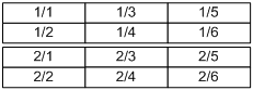
After the system starts up, each AC power supply is allocated a unique local ID randomly. The randomly allocated ID is not convenient for device management, daily maintenance, and fault location because the randomly allocated ID is not related with the slot in which the AC power supply resides. You must manually allocate IDs for the AC power supplies after the installation of the switch for future management. H3C recommends that you allocate IDs for AC power supplies the same as the IDs of the slots where the power supplies reside, as shown in Figure 2 and Figure 3. You can allocate IDs for only PSE9000 AC power supplies. To view the model of a power supply, use the display power-supply command.
For PSE9000-A and PSE9000-D, the switch automatically allocates the ID of the slot where a power supply resides as the power supply ID.
To avoid allocating one ID to multiple AC power supplies, follow these guidelines:
· After installing an AC power supply, wait at least three minutes before installing another.
· After removing an AC power supply, wait at least 15 seconds before installing or removing another.
Figure 2 Power supply slot numbers for the S12508
![]()
Figure 3 Power supply slot numbers for the S12518
After the power-supply led-blink command is executed, the LED of the corresponding power supply blinks for a period of time to show you the location of the power supply. You can configure the time when the LED blinks and how long the LED keeps blinking. If you execute the command without specifying the power supply ID, the LEDs of all power supplies blink one by one in the ascending order of the power supply IDs.
After you allocate IDs to the AC power supplies, and reboot the switch after a period of time, the following rules apply:
· If the locations of the AC power supplies do not change or some AC power supplies are removed during this period of time, the IDs of the AC power supplies do not change after the switch reboots;
· If the locations of the AC power supplies are changed or some new AC power supplies are installed during this period of time, the AC power supplies are allocated new IDs randomly after the switch reboots.
To allocate IDs for AC power supplies:
|
Step |
Command |
Remarks |
|
1. Enter system view. |
system-view |
N/A |
|
2. Configure the time when the LED of the specified power supply blinks and how long the LED keeps blinking. |
· In standalone mode: · In IRF mode: |
Optional. Use either command. By default, the LED blinks for 3 seconds as soon as the command is executed. |
|
3. Allocate new IDs for the specified AC power supplies. |
· In standalone mode: · In IRF mode: |
Use either command. By default, the system allocates IDs for AC power supplies randomly. Each AC power supply can be allocated with only one ID, but different AC power supplies cannot have the same ID. |
The following gives an AC power supply ID allocation configuration example.
The configuration requirements are as follows:
· The switch has three AC power supplies. The system has allocated IDs for the AC power supplies randomly.
· Follow the allocation scheme as shown in Figure 4 to allocate IDs for the AC power supplies manually.
![]()
The configuration procedure is as follows:
1. Execute the power-supply led-blink command to identify the correspondence between the randomly allocated IDs and the AC power supplies.
# Identify the location of the AC power supply with ID 1.
<Sysname> system-view
[Sysname] power-supply led-blink module 1 blink-time 5 delay-time 10
After the command is executed, you can see that the power supply in slot 3 blinks, and thus the ID of the power supply in slot 3 is 1. Execute the power-supply led-blink command to identify the correspondence between the other two AC power supplies and their IDs. The result is shown in Figure 5.
Figure 5 Randomly allocated AC power supply IDs
![]()
2. Use the power-supply module new-id to allocate IDs for AC power supplies according to Figure 4.
<Sysname> system-view
[Sysname] power-supply module 3 1 2 new-id 1 3 5
Configuring temperature thresholds for a card
You can set the temperature threshold to monitor the temperature of a card.
The switch supports lower temperature threshold, warning temperature threshold, and alarming temperature threshold.
· When the card temperature drops below the lower temperature threshold or reaches the warning threshold, the device logs the event and outputs a log message and a trap.
· When the card temperature reaches the alarming threshold, the device logs the event and outputs a log message and a trap repeatedly, and alerts users through the LED on the device panel.
To configure temperature thresholds for a card:
|
Step |
Command |
Remarks |
|
1. Enter system view. |
system-view |
N/A |
|
2. Configure temperature thresholds for a card. |
· In standalone mode: · In IRF mode: |
Optional. |
Isolating and diagnosing a card
When the switch detects a card failure or upgrades the logic of the CPU daughter card on an interface card, you can isolate the faulty card or the CPU daughter card to prevent it from forwarding data packets. This operation allows for convenient on-site diagnosis or upgrading while causing no interference on the operation of the system and services of other cards.
After isolating a card, you can use the test diag-offline command to collect the diagnosis information of the card.
Configuration guidelines
· When you upgrade the logic of an interface card, isolate the interface card first.
· You can use the display device command to view whether a card is isolated, that is, whether the card is in the offline state.
· To minimize the interference on the system operation, H3C recommends that you force a network interface card that is operating correctly offline before you remove it.
· When you execute the test diag-offline command, the path where the diagnosis information is saved is also displayed following the diagnosis information on the terminal. For example, you can see flash:/diag_slot3_20080522_103458.txt.
· H3C recommends that you send the diagnosis information to qualified engineers for analysis.
Configuration procedure
To isolate and diagnose a card:
|
Step |
Command |
Remarks |
|
1. Enter system view. |
system-view |
N/A |
|
2. Isolate a card. |
· In standalone mode: · In IRF mode: |
Use either command. No card is isolated by default. The active MPU cannot be isolated. If only one switching fabric module is working on the switch, it cannot be isolated. |
|
3. Diagnose the card problem. |
· In standalone mode: · In IRF mode: |
Use either command. The diagnosis information will be displayed and saved in logs under the root directory of the flash. Each log is named in the format of diag_slot_time, where slot indicates where the card is located and time indicates when the diagnosis operation is performed. This command can be executed for only isolated cards. Other commands cannot take effect for such a card. |
Configuring in-service hardware failure diagnosis and failure protection
|
|
CAUTION: Before configuring the hardware-failure-protection auto-down command on a port, make sure that a backup link exists to avoid service interruption in case the port is shut down. |
A hardware failure might cause traffic forwarding failures and service interruption. To improve the automatic failure detection and handling capabilities of the switch, you can configure in-service hardware failure diagnosis and failure protection.
The in-service hardware failure diagnosis and failure protection feature covers:
· In-service hardware failure detection for chips, cards, and the forwarding service, and automatic fix actions taken for the detected failures.
· Failure protection for ports. When a hardware failure is detected on a port, the switch automatically shuts down the port.
· Failure protection for aggregation groups. When a hardware failure is detected on a member port of an aggregation group, if the member port is not configured with the hardware-failure-protection auto-down command but it is not the final port in up state in the aggregation group, the port is shut down automatically; if the member port is not configured with the command and it is the final port in up state in the aggregation group, the port will not be shut down; if the member port is configured with the command, the port is shut down automatically no matter whether it is the final port in up state in the aggregation group.
Configuration guidelines
· Because hardware failure protection is enabled on member ports of an aggregation group, use the undo hardware-failure-protection auto-down command to disable this feature for the member ports of all aggregation groups before you enable hardware failure protection for the aggregation groups.
· If a port is automatically shut down due to hardware failure protection, its status displayed with the display interface command is Protect DOWN. To bring up the port, use the undo shutdown command on the port.
· If a card is isolated or its software is not allowed to be loaded due to hardware failure fix operations, you can remove the card and then install it to recover the card status.
· After configuring in-service diagnosis and failure protection, you can use the display hardware-failure-detection command to check the running information of the feature.
Configuration procedure
To configure in-service hardware failure diagnosis and failure protection:
|
Step |
Command |
Remarks |
|
1. Enter system view. |
system-view |
N/A |
|
2. Enable in-service hardware failure detection and configure fix actions taken in case of hardware failures.. |
hardware-failure-detection { chip | board | forwarding } { off | warning | reset | isolate } |
The fix actions taken in case of hardware failures include: · off: Takes no action. · warning: Sends warning messages. · reset: Resets the failed card. · isolate: Shuts down the failed port, isolates the failed card, prohibits the failed card from loaded, or powers off the failed card to reduce the impact of the failure to the system. By default, the fix action taken for all hardware failures is warning. |
|
3. Enable hardware failure protection for aggregation groups. |
hardware-failure-protection aggregation |
Optional. Disabled by default. This command is effective only when the fix action is configured as isolate. |
|
4. Enter Ethernet interface view. |
interface interface-type interface-number |
N/A |
|
5. Configure hardware failure protection for the port. |
hardware-failure-protection auto-down |
Optional. Enabled by default. This command is effective only when the fix action is configured as isolate. |
The hardware-failure-protection aggregation and hardware-failure-protection auto-down command do not take effect on a port in either of the following cases:
· The port is configured with the loopback { external | internal } command.
· The port is configured with the port up-mode command.
· The port is configured as an IRF physical port.
For information about IRF physical ports, see IRF Configuration Guide.
Configuring the size of shared buffers on an interface card
An interface card uses a buffer with a fixed size to buffer the packets received and sent. A buffer comprises multiple storage units. It is divided into two areas: fixed buffer and shared buffer. The fixed buffer is allocated to the interfaces according to a certain algorithm, and the shared buffer is shared by all interfaces. When the traffic of an interface becomes heavy, and the fixed buffer cannot provide sufficient memory, the shared buffer provides temporary memory for the interface.
By default, the fixed buffer and the shared buffer contain a fixed number of storage units. You can configure the number of storage units in the shared buffer as needed. Because the total number of storage units in a buffer is fixed, the number of storage units in the fixed buffer will change after your configuration. You can tune the shared buffer area depending on traffic patterns. If transient large traffic bursts occur on some interfaces, you can expand the shared buffer to accommodate the bursts to prevent traffic loss. If transient small traffic bursts often occur on the interfaces, you can decrease the shared buffer so that each port can get more dedicated buffer memory.
To set the size in blocks of the receive or transmit buffer shared by all interfaces on an interface card:
|
Step |
Command |
Remarks |
|
1. Enter system view. |
system-view |
N/A |
|
2. Set the size in blocks of the receive or transmit buffer shared by all interfaces on an interface card. |
· In standalone mode: · In IRF mode: |
Optional. Use either command. By default, the size in blocks of the shared receive buffer is 1024, and that of the shared transmit buffer is 4096. Only the LST1XP16LEC1, LST1XP16LEC2, and LST1XP16LEB1 cards support the ingress keyword. That is, you can modify the size of the shared receive buffer for these cards. |
Clearing unused 16-bit interface indexes
The device must maintain persistent 16-bit interface indexes and keep one interface index match one interface name for network management. After deleting a logical interface, the device retains its 16-bit interface index so the same index can be assigned to the interface at interface re-creation.
To avoid index depletion causing interface creation failures, you can clear all 16-bit indexes that have been assigned but not in use. The operation does not affect the interface indexes of the interfaces that have been created but the indexes assigned to re-recreated interfaces might change.
A confirmation is required when you execute this command. If you fail to make a confirmation within 30 seconds or enter N to cancel the operation, the command is executed.
To clear unused 16-bit interface indexes:
|
Task |
Command |
Remarks |
|
Clear unused 16-bit interface indexes. |
reset unused porttag |
Available in user view. |
Enabling automatic forwarding path check
When the switch is operating, traffic forwarding exceptions might occur due to hardware failures or other reasons. You can enable automatic forwarding path check so that the switch gives prompts when a forwarding exception occurs. According to the prompts, you can troubleshoot the problem.
To enable automatic forwarding path check:
|
Step |
Command |
Remarks |
|
1. Enter system view. |
system-view |
N/A |
|
2. Enable automatic forwarding path check. |
forward-path check { enable | disable } |
Enabled by default. |
Above the configuration, if a forwarding exception occurs, the switch gives prompts, for example:
%Aug 20 14:55:54:973 2010 H3C DIAG/3/ERROR: -Slot=8; Forwarding fault: slot 5 to slot 8
%Aug 20 14:55:55:084 2010 H3C DIAG/3/ERROR: -Slot=6; Forwarding fault: slot 6 to slot 6
The output shows that a forwarding exception exists between the cards in slot 8 and slot 5, and an exception in internal data forwarding exists on the card in slot 6.
Enabling port recovery for the switch
On an S12518 switch, if the switching fabric module LST1SF18B1 is configured and a 8-port or 32-port 10GE optical Ethernet interface card is installed in any of slots 16 to 19, it might cause some ports on some interface cards unavailable. Table 3 lists the ports that might be affected.
|
Card |
Unavailable port |
|
LST1XP8LEB1 LST1XP8LEC1 LST1XP8LEF1 LST2XP8LEB1 LST2XP8LEC1 LST2XP8LEC2 LST2XP8LEF1 LST3XP8LEB1 LST3XP8LEC1 |
Ports 1, 2, 7 and 8 |
|
LST1XP32REB1 LST1XP32REC1 LST2XP32REB1 LST2XP32REC1 LST2XP32REC2 |
Ports whose IDs are odd numbers |
For port details, see H3C S12500 Product 10GE Optical Ethernet Interface Card Datasheet.
To make these ports operate correctly, use any of the following methods:
· Replace all switching fabric modules with LST2SF18C1 one by one without interrupting services, remove the configuration on the unavailable ports, enable port recovery for the ports, and then configure the ports as needed.
· Power off the switch, replace LST1SF18B1 with LST2SF18C1, and power on the switch.
To enable port recovery for the switch:
|
Step |
Command |
Remarks |
|
1. Enter system view. |
system-view |
N/A- |
|
2. Enable port recovery for the switch. |
In standalone mode: In IRF mode: |
By default, port recovery is disabled. |
Verifying and diagnosing transceiver modules
Table 4 lists the commonly used transceiver modules. They can be further divided into optical transceivers and electrical transceivers based on transmission medium.
Table 4 Commonly used transceiver modules
|
Transceiver type |
Application environment |
Whether can be an optical transceiver |
Whether can be an electrical transceiver |
|
SFP (Small Form-factor Pluggable) |
Generally used for 100M/1000M Ethernet interfaces or POS 155M/622M/2.5G interfaces |
Yes |
Yes |
|
SFP+ (Enhanced 8.5 and 10 Gigabit Small Form-factor Pluggable) |
Generally used for 10G Ethernet interfaces |
Yes |
Yes |
|
XFP (10-Gigabit small Form-factor Pluggable) |
Generally used for 10G Ethernet interfaces |
Yes |
No |
Verifying transceiver modules
You can verify the genuineness of a transceiver module in the following ways:
· Display the key parameters of a transceiver module, including its transceiver type, connector type, central wavelength of the transmit laser, transfer distance and vendor name.
· Display its electronic label. The electronic label is a profile of the transceiver module and contains the permanent configuration including the serial number, manufacturing date, and vendor name. The data is written to the storage component during debugging or testing.
To identify transceiver modules:
|
Task |
Command |
|
Display key parameters of the transceiver modules. |
display transceiver interface [ interface-type interface-number ] [ | { begin | exclude | include } regular-expression ] |
|
Display transceiver modules’ electrical label information. |
display transceiver manuinfo interface [ interface-type interface-number ] [ | { begin | exclude | include } regular-expression ] |
Diagnosing transceiver modules
The device provides the alarm function and the digital diagnosis function for transceiver modules. The digital diagnosis function monitors key transceiver module parameters, including the temperature, voltage, laser bias current, TX power, and RX power.
To diagnose transceiver modules:
|
Task |
Command |
|
Display alarms present on transceiver modules. |
display transceiver alarm interface [ interface-type interface-number ] [ | { begin | exclude | include } regular-expression ] |
|
Display the measured values of the digital diagnosis parameters for transceiver modules. |
display transceiver diagnosis interface [ interface-type interface-number ] [ | { begin | exclude | include } regular-expression ] |
Displaying and maintaining device management
For diagnosis or troubleshooting, you can use separate display commands to collect running status data module by module, or use the display diagnostic-information command to bulk collect running data for multiple modules.
|
Task |
Command |
Remarks |
|
Display alarm information (in standalone mode). |
display alarm [ slot slot-number ] [ | { begin | exclude | include } regular-expression ] |
Available in any view. |
|
Display alarm information (in IRF mode). |
display alarm [ chassis chassis-number slot slot-number ] [ | { begin | exclude | include } regular-expression ] |
Available in any view. |
|
Display the system version information. |
display version [ | { begin | exclude | include } regular-expression ] |
Available in any view. |
|
Display the system time information. |
display clock [ | { begin | exclude | include } regular-expression ] |
Available in any view. |
|
Display clipboard information. |
display clipboard [ | { begin | exclude | include } regular-expression ] |
Available in any view. |
|
Display or save statistics of the running status of multiple modules. |
display diagnostic-information [ | { begin | exclude | include } regular-expression ] |
Available in any view. |
|
Display the configuration of the shared buffer on an interface card (in standalone mode). |
display buffer-manage configuration [ slot slot-number ] [ | { begin | exclude | include } regular-expression ] |
Available in any view. |
|
Display the configuration of the shared buffer on an interface card (in IRF mode). |
display buffer-manage configuration [ chassis chassis-number slot slot-number ] [ | { begin | exclude | include } regular-expression ] |
Available in any view. |
|
Display the statistics of the CPU usage (in standalone mode). |
display cpu-usage [ slot slot-number [ cpu cpu-number ] ] [ | { begin | exclude | include } regular-expression ] display cpu-usage entry-number [ offset ] [ verbose ] [ slot slot-number [ cpu cpu-number ] ] [ from-device ] [ | { begin | exclude | include } regular-expression ] |
Available in any view. |
|
Display the statistics of the CPU usage (in IRF mode). |
display cpu-usage [ chassis chassis-number slot slot-number [ cpu cpu-number ] ] [ | { begin | exclude | include } regular-expression ] display cpu-usage entry-number [ offset ] [ verbose ] [ chassis chassis-number slot slot-number [ cpu cpu-number ] ] [ from-device ] [ | { begin | exclude | include } regular-expression ] |
Available in any view. |
|
Display history statistics of the CPU usage in a chart (in standalone mode). |
display cpu-usage history [ task task-id ] [ slot slot-number [ cpu cpu-number ] ] [ | { begin | exclude | include } regular-expression ] |
Available in any view. |
|
Display history statistics of the CPU usage in a chart (in IRF mode). |
display cpu-usage history [ task task-id ] [ chassis chassis-number slot slot-number [ cpu cpu-number ] ] [ | { begin | exclude | include } regular-expression ] |
Available in any view. |
|
Display device information (in standalone mode). |
display device [ cf-card ] [ slot slot-number [ subslot subslot-number ] | verbose ] [ | { begin | exclude | include } regular-expression ] |
Available in any view. |
|
Display device information (in IRF mode). |
display device [ cf-card ] [ [ chassis chassis-number [ slot slot-number [ subslot subslot-number ] ] ] | verbose ] [ | { begin | exclude | include } regular-expression ] |
Available in any view. |
|
Display the electrical label information of the cards and power monitoring modules on the switch (in standalone mode). |
display device manuinfo [ slot slot-number ] [ | { begin | exclude | include } regular-expression ] |
Available in any view. |
|
Display the electrical label information of the cards and power monitoring modules on the member switch (in IRF mode). |
display device manuinfo [ chassis chassis-number [ slot slot-number ] ] [ | { begin | exclude | include } regular-expression ] |
Available in any view. |
|
Display the electrical label information of the specified chassis backplane (in standalone mode). |
display device manuinfo chassis-only [ | { begin | exclude | include } regular-expression ] |
Available in any view. |
|
Display the electrical label information of the specified chassis backplane (in IRF mode). |
display device manuinfo chassis chassis-number chassis-only [ | { begin | exclude | include } regular-expression ] |
Available in any view. |
|
Display the electrical label information of the specified fan (in standalone mode). |
display device manuinfo fan fan-id [ | { begin | exclude | include } regular-expression ] |
Available in any view. |
|
Display the electrical label information of the specified fan (in IRF mode). |
display device manuinfo chassis chassis-number fan fan-id [ | { begin | exclude | include } regular-expression ] |
Available in any view. |
|
Display the electrical label information of the specified power supply (in standalone mode). |
display device manuinfo power power-id [ | { begin | exclude | include } regular-expression ] |
Available in any view. |
|
Display the electrical label information of the specified power supply (in IRF mode). |
display device manuinfo chassis chassis-number power power-id [ | { begin | exclude | include } regular-expression ] |
Available in any view. |
|
Display the electronic label of the specified power monitor module (in standalone mode). |
display device manuinfo power-monitor pmu-id [ | { begin | exclude | include } regular-expression ] |
Available in any view. |
|
Display the electronic label of the specified power monitor module (in IRF mode). |
display device manuinfo chassis chassis-number power-monitor pmu-id [ | { begin | exclude | include } regular-expression ] |
Available in any view. |
|
Display the temperature information of the switch (in standalone mode). |
display environment [ slot slot-number ] [ | { begin | exclude | include } regular-expression ] |
|
|
Display the temperature information of an member switch (in IRF mode). |
display environment [ chassis chassis-number [ slot slot-number ] ] [ | { begin | exclude | include } regular-expression ] |
Available in any view. |
|
Display the operating state of fans in the switch (in standalone mode). |
display fan [ verbose ] [ | { begin | exclude | include } regular-expression ] |
Available in any view. |
|
Display the operating state of fans in an IRF member switch (in IRF mode). |
display fan [ chassis chassis-number ] [ verbose ] [ | { begin | exclude | include } regular-expression ] |
Available in any view. |
|
Display the automatic speed adjustment mode of fans in the switch (in standalone mode). |
display fan auto-control-mode [ | { begin | exclude | include } regular-expression ] |
Available in any view. |
|
Display the automatic speed adjustment mode of fans in an IRF member switch (in IRF mode). |
display fan auto-control-mode chassis chassis-number [ | { begin | exclude | include } regular-expression ] |
Available in any view. |
|
Display hardware failure detection and fix operation records. |
display hardware-failure-detection [ | { begin | exclude | include } regular-expression ] |
Available in any view. |
|
Display hardware failure protection information. |
display hardware-failure-protection [ | { begin | exclude | include } regular-expression ] |
Available in any view. |
|
Display the usage of the memory of the switch (in standalone mode). |
display memory [ slot slot-number [ cpu cpu-number ] ] [ | { begin | exclude | include } regular-expression ] |
Available in any view. |
|
Display the usage of the memory of an IRF member switch (in IRF mode). |
display memory [ chassis chassis-number slot slot-number [ cpu cpu-number ] ] [ | { begin | exclude | include } regular-expression ] |
Available in any view. |
|
Display the power state of the switch (in standalone mode). |
display power-supply [ verbose ] [ | { begin | exclude | include } regular-expression ] |
Available in any view. |
|
Display the power state of an IRF member switch (in IRF mode). |
display power-supply [ chassis chassis-number ] [ verbose ] [ | { begin | exclude | include } regular-expression ] |
Available in any view. |
|
Display the configuration of the scheduled job configured by the schedule job command. |
display schedule job [ | { begin | exclude | include } regular-expression ] |
Available in any view. |
|
Display the reboot time of the switch. |
display schedule reboot [ | { begin | exclude | include } regular-expression ] |
Available in any view. |
|
Display brief information about the hardware configuration file. |
display system config file [ file-url ] [ | { begin | exclude | include } regular-expression ] |
Available in any view. |
|
Display the system operating mode. |
display system working mode [ | { begin | exclude | include } regular-expression ] |
Available in any view. |
|
Display the configuration of scheduled jobs configured by the job command. |
display job [ job-name ] [ | { begin | exclude | include } regular-expression ] |
Available in any view. |
The display commands discussed above are for the global configuration. For the display command for specific protocol and interface, see corresponding sections.