- Table of Contents
-
- 07-Layer 3 - IP Routing Configuration Guide
- 00-Preface
- 01-Basic IP Routing Configuration
- 02-Static Routing Configuration
- 03-RIP Configuration
- 04-OSPF Configuration
- 05-IS-IS Configuration
- 06-BGP Configuration
- 07-Policy-Based Routing Configuration
- 08-Guard Route Configuration
- 09-IPv6 Static Routing Configuration
- 10-RIPng Configuration
- 11-OSPFv3 Configuration
- 12-IPv6 IS-IS Configuration
- 13-IPv6 BGP Configuration
- 14-IPv6 Policy-Based Routing Configuration
- 15-Routing Policy Configuration
- 16-Tunnel End Packets Policy Routing Configuration
- Related Documents
-
| Title | Size | Download |
|---|---|---|
| 04-OSPF Configuration | 934.69 KB |
Contents
Configuring OSPF network types
Configuring the broadcast network type for an interface
Configuring the NBMA network type for an interface
Configuring the P2MP network type for an interface
Configuring the P2P network type for an interface
Configuring OSPF route control
Configuring OSPF route summarization
Configuring OSPF inbound route filtering
Configuring ABR Type-3 LSA filtering
Configuring an OSPF cost for an interface
Configuring the maximum number of ECMP routes
Configuring OSPF route redistribution
Tuning and optimizing OSPF networks
Configuring OSPF packet timers
Specifying an LSA transmission delay
Specifying SPF calculation interval
Specifying the LSA arrival interval
Specifying the LSA generation interval
Disabling interfaces from receiving and sending OSPF packets
Configuring OSPF authentication
Adding the interface MTU into DD packets
Configuring the maximum number of external LSAs in LSDB
Enabling compatibility with RFC 1583
Logging neighbor state changes
Configuring OSPF network management
Enabling the advertisement and reception of opaque LSAs
Configuring OSPF to give priority to receiving and processing hello packets
Configuring the LSU transmit rate
Configuring OSPF Graceful Restart
Configuring the OSPF GR restarter
Configuring the OSPF GR helper
Triggering OSPF Graceful Restart
Configuring bidirectional control detection
Configuring single-hop echo detection
Displaying and maintaining OSPF
Configuring OSPF route redistribution
Configuring OSPF to advertise a summary route
Configuring OSPF virtual links
OSPF Graceful Restart configuration example
OSPF NSR configuration example
Troubleshooting OSPF configuration
No OSPF neighbor relationship established
Open Shortest Path First (OSPF) is a link state interior gateway protocol developed by the OSPF working group of the Internet Engineering Task Force (IETF). OSPF version 2 is used for IPv4. Unless otherwise noted, OSPF refers to OSPFv2 throughout this chapter.
Introduction to OSPF
OSPF has the following features:
· Wide scope—Supports various networks sizes and up to several hundred routers in an OSPF routing domain.
· Fast convergence—Advertises routing updates instantly upon network topology changes.
· Loop free—Computes routes with the SPF algorithm to avoid routing loops.
· Area-based network partition—Splits an AS into multiple areas to facilitate management. This feature reduces the lSDB size on routers to save memory and CPU resources, and reduces route updates transmitted between areas to save bandwidth.
· Equal-cost multi-path (ECMP) routing—Supports multiple equal-cost routes to a destination.
· Routing hierarchy—Supports a 4-level routing hierarchy that prioritizes routes into intra-area, inter-area, external Type-1, and external Type-2 routes.
· Authentication— Supports area- and interface-based packet authentication to ensure the security of packet exchange.
· Support for multicasting—Multicasts protocol packets on some types of links to avoid impacting other devices.
Basic concepts
Autonomous system
A group of routers running the same routing protocol constitute an autonomous system (AS).
Route calculation
OSPF computes routes as follows:
· Each router generates Link State Advertisements (LSAs) based on the network topology around itself, and sends them to other routers in update packets.
· Each OSPF router collects LSAs from other routers to compose a link state database (LSDB). An LSA describes the network topology around a router, and the LSDB describes the entire network topology of the area.
· Each router transforms the LSDB to a weighted directed graph that shows the topology of the area. All the routers within the area have the same graph.
· Each router uses the SPF algorithm to compute a shortest path tree that shows the routes to the nodes in the area. The router itself is the root of the tree.
Router ID
An OSPF process running on a router must have its own router ID, which is a 32-bit unsigned integer, the unique identifier of the router in the AS.
OSPF packets
OSPF uses the following packet types:
· Hello—Periodically sent to find and maintain neighbors, containing the values of some timers, information about the DR, BDR, and known neighbors.
· Database description (DD)—Describes the digest of each LSA in the LSDB, exchanged between two routers for data synchronization.
· Link state request (LSR)—Requests needed LSAs from the neighbor. After exchanging the DD packets, the two routers know which LSAs of the neighbor are missing from their LSDBs. They then send an LSR packet to each other, requesting the missing LSAs. The LSA packet contains the digest of the missing LSAs.
· Link state update (LSU)—Transmits the requested LSAs to the neighbor.
· Link state acknowledgment (LSAck)—Acknowledges received LSU packets. It contains the headers of received LSAs (an LSAck packet can acknowledge multiple LSAs).
LSA types
OSPF advertises routing information in LSAs. The following describes some commonly used LSAs:
· Router LSA—Type-1 LSA, originated by all routers, flooded throughout a single area only. This LSA describes the collected states of the router's interfaces to an area.
· Network LSA—Type-2 LSA, originated for broadcast and NBMA networks by the designated router, flooded throughout a single area only. This LSA contains the list of routers connected to the network.
· Network Summary LSA—Type-3 LSA, originated by Area Border Routers ABRs (ABRs), and flooded throughout the LSA's associated area. Each summary-LSA describes a route to a destination outside the area, yet still inside the AS (an inter-area route).
· ASBR Summary LSA—Type-4 LSA, originated by ABRs and flooded throughout the LSA's associated area. Type 4 summary-LSAs describe routes to Autonomous System Boundary Router (ASBR).
· AS External LSA—Type-5 LSA, originated by ASBRs, and flooded throughout the AS (except stub and NSSA areas). Each AS-external-LSA describes a route to another AS.
· NSSA LSA—Type-7 LSA, as defined in RFC 1587, originated by ASBRs in Not-So-Stubby Areas (NSSAs) and flooded throughout a single NSSA. NSSA LSAs describe routes to other ASs.
· Opaque LSA—A proposed type of LSA, the format consisting of a standard LSA header and application specific information. Opaque LSAs are used by the OSPF protocol or by some application to distribute information into the OSPF routing domain. The opaque LSA includes three types, Type 9, Type 10, and Type 11, which are used to flood into different areas. The Type 9 opaque LSA is flooded into the local subnet, the Type 10 is flooded into the local area, and the Type 11 is flooded throughout the AS.
Neighbor and adjacency
In OSPF, neighbor and adjacency are different concepts.
Neighbor—After startup, OSPF sends a hello packet on each OSPF interface. A router that receives the hello packet checks parameters in the packet. If the parameters match its own, the router considers the sending router an OSPF neighbor.
Adjacency—Two OSPF neighbors establish an adjacency relationship to synchronize their LSDBs. Any two neighbors not exchanging route information will not establish an adjacency.
OSPF areas
Network partition
In a large OSPF routing domain, SPF route computations consume too many storage and CPU resources, and enormous OSPF packets generated for route synchronization occupy excessive bandwidth.
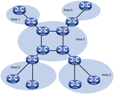
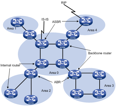
To solve these problems, OSPF splits an AS into multiple areas. Each area is identified by an area ID. The boundaries between areas are routers rather than links. A network segment (or a link) can only reside in one area, as shown in Figure 1.
You can configure route summarization on ABRs to reduce the number of LSAs advertised to other areas and minimize the effect of topology changes.
Figure 1 Area based OSPF network partition
Backbone area and virtual links
Each AS has a backbone area that distributes routing information between non-backbone areas. Routing information between non-backbone areas must be forwarded by the backbone area. Therefore, OSPF requires the following:
· All non-backbone areas must maintain connectivity to the backbone area.
· The backbone area itself must maintain connectivity.
In practice, the requirements might not be met due to lack of physical links. OSPF virtual links can solve this problem.
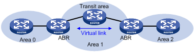
A virtual link is established between two ABRs through a non-backbone area and is configured on both ABRs to take effect. The non-backbone area is called a transit area.
In Figure 2, Area 2 has no direct physical link to the backbone area 0. You can configure a virtual link between the two ABRs to connect Area 2 to the backbone area.
Figure 2 Virtual link application 1
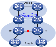
Virtual links can also be used to provide redundant links. If the backbone area cannot maintain internal connectivity due to the failure of a physical link, you can configure a virtual link to replace the failed physical link, as shown in Figure 3.
Figure 3 Virtual link application 2
The virtual link between the two ABRs acts as a point-to-point connection. You can configure interface parameters, such as hello packet interval, on the virtual link as they are configured on physical interfaces.
The two ABRs on the virtual link exchange OSPF packets with each other directly, and the OSPF routers in between simply convey these OSPF packets as normal IP packets.
Stub area
A stub area does not distribute Type-5 LSAs to reduce the routing table size and amount of routing information in this area.
To further reduce the routing table size and the amount of routing information in this area, you can configure the stub area as a totally stub area. The ABR of a totally stub area does not advertise inter-area routes or AS-external routes.
(Totally) stub area configuration is optional, and not every area is eligible to be a stub area. In general, a stub area resides on the border of the AS. The ABR of a stub area advertises a default route in a Type-3 LSA so that the routers in the area can reach external networks through the default route.
Note the following when you configure a (totally) stub area:
· You cannot configure the backbone area as a (totally) stub area.
· To configure an area as a stub area, issue the stub command on routers attached to the area.
· To configure an area as a totally stub area, issue the stub command on routers attached to the area, and issue the stub [ no-summary ] command on the ABR of the area.
· A (totally) stub area cannot have an ASBR because AS external routes cannot be distributed into the stub area.
· Virtual links cannot transit (totally) stub areas.
NSSA area
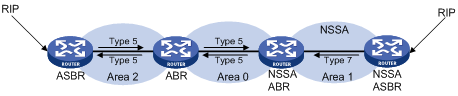
Similar to a stub area, an NSSA area does not import AS external LSA (Type-5 LSA) but can import Type-7 LSAs generated by the NSSA ASBR. The NSSA ABR translates Type-7 LSAs into Type-5 LSAs and advertises the Type-5 LSAs to other areas.
In Figure 4, the OSPF AS contains three areas: Area 1, Area 2, and Area 0. The other two ASs run RIP. Area 1 is an NSSA area where the ASBR redistributes RIP routes in Type-7 LSAs into Area 1. Upon receiving these Type-7 LSAs, the NSSA ABR translates them to Type-5 LSAs, and then advertises the Type-5 LSAs to Area 0.
The ASBR of Area 2 redistributes RIP routes in Type-5 LSAs into the OSPF routing domain. However, Area 1 does not receive these Type-5 LSAs because it is an NSSA area.
Virtual links cannot transit NSSA areas.
Comparison between the areas
Figure 5 Comparison between the areas
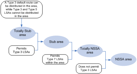
Figure 5 shows the following comparison of the areas:
· In a totally stub area, the ABR can distribute a Type-3 default route, while it does not distribute external routes and inter-area routes.
· Compared with a totally stub area, a stub area can import inter-area routes.
· Compared with a stub area, an NSSA area can import external routes through Type-7 LSAs advertised by the ASBR.
· Compared with an NSSA area, a totally NSSA area does not import inter-area routes.
Router types
Router classification
OSPF classifies routers into the following types based on their positions in the AS:
· Internal router—All interfaces on an internal router belong to one OSPF area.
· Area Border Router (ABR)—Belongs to more than two areas, one of which must be the backbone area. An ABR connects the backbone area to a non-backbone area. An ABR and the backbone area can be connected through a physical or logical link.
· Backbone router—At least one interface of a backbone router must reside in the backbone area. All ABRs and internal routers in area 0 are backbone routers.
· Autonomous System Boundary Router (ASBR)—Exchanges routing information with another AS. An ASBR might not reside on the border of the AS. It can be an internal router or ABR.
Figure 6 OSPF router types
Route types
OSPF prioritizes routes into the following levels:
· Intra-area route
· Inter-area route
· Type-1 external route
· Type-2 external route
The intra-area and inter-area routes describe the network topology of the AS. The external routes describe routes to external ASs.
OSPF classifies external routes into the following types: Type-1 and Type-2. A Type-1 external route has high credibility. The cost from a router to the destination of the Type-1 external route = the cost from the router to the corresponding ASBR+ the cost from the ASBR to the destination of the external route.
A Type-2 external route has low credibility. OSPF considers the cost from the ASBR to the destination of the Type-2 external route is much greater than the cost from the ASBR to an OSPF internal router. The cost from the internal router to the destination of the Type-2 external route = the cost from the ASBR to the destination of the Type-2 external route. If two routes to the same destination have the same cost, OSPF takes the cost from the router to the ASBR into consideration to determine the best route.
OSPF network classification
OSPF network types
OSPF classifies networks into the following types depending on different link layer protocols:
· Broadcast—If the link layer protocol is Ethernet or FDDI, OSPF considers the network type as broadcast by default. On a broadcast network, hello, LSU, and LSAck packets are multicast to 224.0.0.5 that identifies all OSPF routers or 224.0.0.6 that identifies the DR, while DD packets and LSR packets are unicast.
· NBMA (Non-Broadcast Multi-Access)—If the link layer protocol is Frame Relay, ATM, or X.25, OSPF considers the network type as NBMA by default. OSPF packets are unicast on a NBMA network.
· P2MP (point-to-multipoint)—By default, OSPF considers no link layer protocol as P2MP, which is a conversion from other network types such as NBMA. On a P2MP network, OSPF packets are multicast to 224.0.0.5.
· P2P (point-to-point)—If the link layer protocol is PPP or HDLC, OSPF considers the network type as P2P. On a P2P network, OSPF packets are multicast to 224.0.0.5.
NBMA network configuration guidelines
Typical NBMA networks include ATM and Frame Relay networks.
Because NBMA interfaces cannot broadcast hello packets, you must specify neighbors manually and configure DR priorities for the neighbors.
An NBMA network is fully meshed, which means any two routers in the NBMA network have a direct virtual circuit for communication. If direct connections are not available between some routers, the network type of interfaces associated should be configured as P2MP. If such an interface has only one neighbor, configure its network type as P2P.
The following are the differences between NBMA and P2MP networks:
· NBMA networks are fully meshed, non-broadcast, and multi access. P2MP networks are not required to be fully meshed.
· NBMA networks require DR and BDR election. P2MP networks do not have DR or BDR.
· NBMA is the default network type. P2MP is a conversion from another network type, such as NBMA.
· On a NBMA network, OSPF packets are unicast, and neighbors are configured manually on routers. On a P2MP network, OSPF packets are multicast.
DR and BDR
On a broadcast or NBMA network, any two routers must establish an adjacency to exchange routing information with each other. If n routers are present on the network, n(n-1)/2 adjacencies are required. Any topology change on the network results in an increase in traffic for route synchronization, consuming many system and bandwidth resources.
The DR and BDR mechanisms can solve the problem.
· DR—Elected to advertise routing information among other routers. If the DR fails, routers on the network must elect another DR and synchronize information with the new DR. Using this mechanism alone is time-consuming and prone to route calculation errors.
· BDR—Elected along with the DR to establish adjacencies with all other routers. When the DR fails, the BDR immediately becomes the new DR, and other routers elect a new BDR.
Routers other than the DR and BDR are called "DrOthers." They do not establish adjacencies with one another, so the number of adjacencies is reduced.
The role of a router is subnet (or interface) specific. It might be a DR on one interface and a BDR or DROther on another interface.
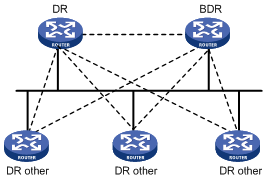
In Figure 7, solid lines are Ethernet physical links, and dashed lines represent OSPF adjacencies. With the DR and BDR, only seven adjacencies are established.
Figure 7 DR and BDR in a network
DR and BDR election
DR election is performed on broadcast or NBMA networks but not on P2P or P2MP networks.
Routers in a broadcast or NBMA network elect the DR and BDR by router priorities and router IDs. Routers with a router priority value higher than 0 are candidates for DR and BDR election.
The election votes are hello packets. Each router sends the DR elected by itself in a hello packet to all the other routers. If two routers on the network declare themselves as the DR, the router with the higher router priority wins. If router priorities are the same, the router with the higher router ID wins. In addition, a router with the router priority 0 cannot become the DR or BDR.
If a router with a higher router priority is added to the network after DR and BDR election, the router cannot become the DR or BDR immediately because no DR election is performed for it. Therefore, the DR of a network might not be the router with the highest priority, and the BDR might not be the router with the second highest priority.
OSPF packet formats
OSPF packets are directly encapsulated into IP packets. OSPF uses the IP protocol number 89. The format of an OSPF LSU packet format is shown in Figure 8.
![]()
OSPF packet header
OSPF packets are classified into five types that have the same packet header, as shown in Figure 9.
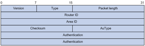
Major fields of the OSPF packet header are as follows:
· Version—OSPF version number, which is 2 for OSPFv2.
· Type—OSPF packet type from 1 to 5, corresponding to hello, DD, LSR, LSU, and LSAck.
· Packet length—Total length of the OSPF packet in bytes, including the header.
· Router ID—ID of the advertising router.
· Area ID—ID of the area where the advertising router resides.
· Checksum—Checksum of the message.
· AuType—Authentication type from 0 to 2, corresponding to non-authentication, simple (plaintext) authentication, and MD5 authentication.
· Authentication—Information determined by authentication type. It is not defined for authentication type 0. It is defined as password information for authentication type 1, and defined as Key ID, MD5 authentication data length, and sequence number for authentication type 2.
|
|
NOTE: MD5 authentication data is added following an OSPF packet rather than contained in the Authentication field. |
Hello packet
A router sends hello packets periodically to find and maintain neighbor relationships, and to elect the DR or BDR. A hello packet includes information about values of timers, DR, BDR, and neighbors already known.
Figure 10 Hello packet format

Major fields of the hello packet are as follows:
· Network mask—Network mask associated with the router's sending interface. If two routers have different network masks, they cannot become neighbors.
· HelloInterval—Interval for sending hello packets. If two routers have different intervals, they cannot become neighbors.
· Rtr Pri—Router priority. A value of 0 means the router cannot become the DR or BDR.
· RouterDeadInterval—Time before declaring a silent router down. If two routers have different dead intervals, they cannot become neighbors.
· Designated router—IP address of the DR.
· Backup designated router—IP address of the BDR.
· Neighbor—Router ID of the neighbor router.
DD packet
Two routers exchange database description (DD) packets describing their LSDBs for database synchronization. A DD packet contains only the headers of LSAs to reduce traffic between routers.
Figure 11 DD packet format
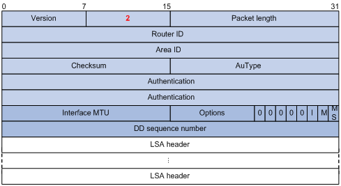
Major fields of the DD packets are as follows:
· Interface MTU—Specifies the largest IP datagram in bytes that the interface can send without fragmentation.
· I (Initial)—The Init bit, which is set to 1 if the packet is the first DD packet, and set to 0 if not.
· M (More)—The More bit, which is set to 0 if the packet is the last DD packet, and set to 1 if more DD packets are to follow.
· MS (Master/Slave)—The Master/Slave bit. When set to 1, it indicates that the router is the master during the database exchange process. Otherwise, the router is the slave router.
· DD sequence number—Used to sequence the collection of DD packets. The initial value is set by the master. The DD sequence number then increments until the complete database description has been sent.
LSR packet
After exchanging DD packets, two routers know which LSAs of the peer are missing from the local LSDB. Then, they send LSR (link state request) packets to request the missing LSAs. An LSR packet contains the digests of the missing LSAs.
Figure 12 LSR packet format
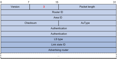
Major fields of the LSR packets are as follows:
· LS type—Type of the LSA to be requested. Type 1, for example, indicates the Router LSA.
· Link state ID—Determined by LSA type.
· Advertising router—ID of the router that sent the LSA.
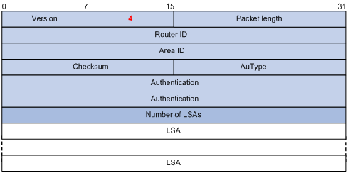
LSU packet
LSU (Link State Update) packets are used to send the requested LSAs to the peer. Each packet carries a collection of LSAs.
Figure 13 LSU packet format
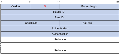
LSAck packet
Link State Acknowledgment (LSAck) packets are used to acknowledge received LSU packets. An LSAck packet carries the headers of LSAs to be acknowledged.
Figure 14 LSAck packet format
LSA header format
All LSAs have the same header.
Figure 15 LSA header format
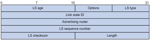
Major fields of the LSA header are as follows:
· LS age—Time (in seconds) elapsed since the LSA was originated. An LSA ages in the LSDB (added by one per second), but does not age in transmission.
· LS type—Type of the LSA.
· Link state ID—The contents of this field depend on the LSA's type.
· Advertising router—ID of the router that originates the LSA.
· LS sequence number—Used by other routers to judge new and old LSAs.
· LS checksum—Checksum of the LSA except the LS age field.
· Length—Length (in bytes) of the LSA, including the LSA header.
LSAs formats
· Router LSA
Figure 16 Router LSA format
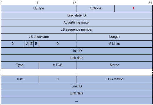
Major fields of the Router LSA are as follows:
¡ Link state ID—ID of the router originating the LSA.
¡ V (Virtual Link)—Set to 1 if the router originating the LSA is a virtual link endpoint.
¡ E (External)—Set to 1 if the router originating the LSA is an ASBR.
¡ B (Border)—Set to 1 if the router originating the LSA is an ABR.
¡ # Links—Number of router links (interfaces) to the area, as described in the LSA.
¡ Link ID—Determined by link type.
¡ Link data—Determined by link type.
¡ Type—Link type. A value of 1 indicates a point-to-point link to a remote router; a value of 2 indicates a link to a transit network; a value of 3 indicates a link to a stub network; and a value of 4 indicates a virtual link.
¡ #TOS—Number of different TOS metrics given for this link. If no TOS metric is given for the link, this field is set to 0. TOS is not supported in RFC 2328. The #TOS field is reserved for early versions of OSPF.
¡ Metric—Cost of using this router link.
¡ TOS—IP Type of Service that this metric refers to.
¡ TOS metric—TOS-specific metric information.
· Network LSA
A Network LSA is originated by the DR on a broadcast or NBMA network. The LSA describes all routers attached to the network.
Figure 17 Network LSA format
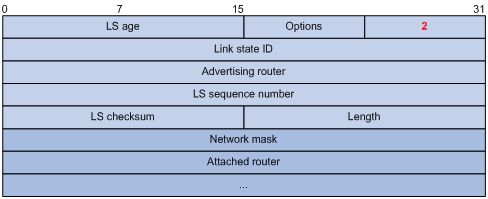
Major fields of the Network LSA are as follows:
¡ Link state ID—The interface address of the DR.
¡ Network mask—The mask of the network (a broadcast or NBMA network).
¡ Attached router—The IDs of the routers, which are adjacent to the DR, including the DR itself.
· Summary LSA
Network summary LSAs (Type-3 LSAs) and ASBR summary LSAs (Type-4 LSAs) are originated by ABRs. Except for the Link state ID field, the formats of Type-3 and Type-4 summary LSAs are identical.
Figure 18 Summary LSA format
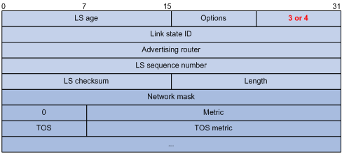
Major fields of the Summary LSA are as follows:
¡ Link state ID—For a Type-3 LSA, it is an IP address outside the area. For a Type-4 LSA, it is the router ID of an ASBR outside the area.
¡ Network mask—The network mask for the Type-3 LSA. It is set to 0.0.0.0 for the Type-4 LSA.
¡ Metric—The metric to the destination.
|
|
NOTE: A Type-3 LSA can be used to advertise a default route if the Link state ID and Network mask are set to 0.0.0.0. |
· AS external LSA
An AS external LSA originates from an ASBR, and describes routing information to a destination outside the AS.
Figure 19 AS external LSA format
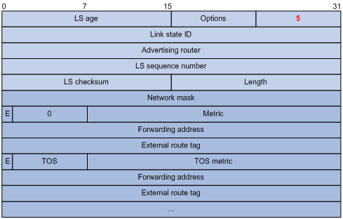
Major fields of the AS external LSA are as follows:
¡ Link state ID—he IP address of another AS to be advertised. When describing a default route, the Link state ID is always set to default destination (0.0.0.0) and the network mask is set to 0.0.0.0.
¡ Network mask—The IP address mask for the advertised destination.
¡ E (External Metric)—The type of the external metric value, which is set to 1 for type 2 external routes, and set to 0 for type 1 external routes. For description of external route types, see "Route types."
¡ Metric—The metric to the destination.
¡ Forwarding address—Data traffic for the advertised destination is forwarded to this address.
¡ External route tag—A tag attached to each external route. This is not used by OSPF. It can be used to manage external routes.
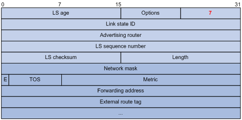
· NSSA external LSA
An NSSA external LSA originates from the ASBR in an NSSA, and is flooded in the NSSA area only. It has the same format as the AS external LSA.
Figure 20 NSSA external LSA format
· Grace LSA
Originating from the GR restarter, a Grace LSA is sent to GR helpers, notifying them of a Graceful Restart.
Figure 21 Grace LSA format
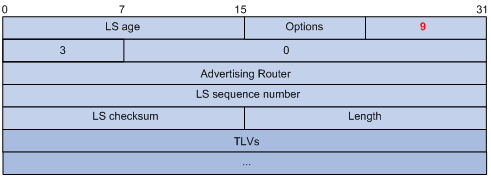
Major field of the Grace LSA is as follows:
TLVs—The defined TLV information includes the length of the grace period (with Type value 1), the reason for the graceful restart (with Type value 2), and the IP interface address of the restarting router (with Type value 3).
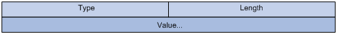
Figure 22 TLV format
Supported OSPF features
Multiprocess
With multiprocess support, multiple OSPF processes can run on a router simultaneously and independently. Routing information interactions between different processes seem like interactions between different routing protocols. Multiple OSPF processes can use the same router ID.
An interface of a router can only belong to a single OSPF process.
Authentication
OSPF can authenticate OSPF packets. Only packets that pass the authentication are received. If an incoming hello packet cannot pass authentication, the neighbor relationship cannot be established.
The authentication type for interfaces attached to a single area must be identical. Authentication types include non-authentication, plaintext authentication, and MD5 ciphertext authentication. The authentication password for interfaces attached to a network segment must be identical.
Active/Standby failover
OSPF backs up necessary information from the active main processing unit (MPU) to the standby MPU. Once the active MPU fails, the standby MPU begins to work to ensure the normal operation of OSPF.
OSPF provides the following backup modes:
· Non-stop Routing (NSR), which backs up all OSPF data to the standby MPU to make sure that OSPF recovers immediately upon an active/standby switchover.
· Graceful Restart (GR), which backs up only the OSPF configuration information to the standby MPU. Once an active/standby switchover occurs, OSPF performs GR to synchronize the LSDB with neighbors.
OSPF GR
GR ensures the continuity of packet forwarding when a routing protocol restarts or an active/standby switchover occurs:
· GR restarter—Graceful restarting router. It must have GR capability.
· GR helper—A neighbor of the GR restarter. It helps the GR restarter to complete the GR process.
After an OSPF GR restarter restarts, it must perform the following tasks:
· Obtain OSPF neighbor information.
· Obtain the LSDB.
Before restart, the GR restarter negotiates GR capability with GR helpers. During the restart of the GR restarter, GR helpers still advertise their adjacencies with the GR restarter. After restart, the GR restarter sends GR helpers an OSPF GR signal so that the GR helpers do not reset their neighbor relationships with the GR restarter. Upon receiving responses from neighbors, the GR restarter creates the neighbor relationships.
After that, the GR restarter synchronizes the LSDB with GR-capable neighbors, updates its routing table and forwarding table, and removes stale routes.
OSPF NSR
With OSPF NSR, the active MPU and the standby MPU have consistent data information, which includes the system operational data, and OSPF-related static and dynamic data. Upon an active/standby switchover, the standby MPU takes over all services from the active MPU seamlessly without impacting other services.
TE and DS-TE
OSPF Traffic Engineering (TE) provides for the establishment and maintenance of Label Switched Paths (LSPs) of TE.
When establishing Constraint-based Routed LSPs (CR LSPs), MPLS obtains the TE information of links in the area through OSPF.
OSPF has a new LSA, Opaque LSA, which can be used for carrying TE information.
DiffServ Aware TE (DS-TE) provides for network resource optimization and allocation, flow classification, and indication of network bandwidth consumption of each flow in a link. TE is implemented on the classified type (thin granularity summarization type) rather than the summarized type (thick granularity summarization type) to improve performance and bandwidth utilization.
To support DS-TE application in MPLS, OSPF supports Local Overbooking Multiplier TLV and Bandwidth Constraint (BC) TLV.
For OSPF TE configuration, see MPLS Configuration Guide.
IGP shortcut and forwarding adjacency
IGP shortcut and forwarding adjacency enable OSPF to use an LSP as the output interface for a destination. Without them, OSPF cannot use the LSP as the output interface.
Differences between IGP shortcut and forwarding adjacency:
· If forwarding adjacency is enabled only, OSPF can also use an LSP as the output interface for a destination
· If IGP shortcut is enabled only, only the router enabled with it can use LSPs for routing.
For configuration of this feature, see MPLS Configuration Guide.
VPN support
OSPF supports VPN, which can run on PEs in VPN networks.
In BGP MPLS VPNs, multiple sites in the same VPN can use OSPF as the internal routing protocol, but they are treated as different ASs. An OSPF route learned by a site will be forwarded to another site as an external route, which leads to heavy OSPF routing traffic and management issues.
To solve this problem, domain IDs are used to differentiate VPNs. Sites in the same VPN are considered as directly connected. PE routers can exchange OSPF routing information like on a dedicated line, so network management and OSPF operation efficiency are improved.
For configuration of this feature, see MPLS Configuration Guide.
OSPF sham link
An OSPF sham link is a point-to-point link between two PE routers on the MPLS VPN backbone.
In general, BGP peers exchange routing information on the MPLS VPN backbone by using the BGP extended community attributes. OSPF running on the remote PE uses the routing information to originate Type-3 summary LSAs (inter-area routes) transmitted to CEs.
If a CE has an intra-area route (backdoor route) to another CE, VPN traffic will always travel on the backdoor route rather than the corresponding inter-area route because an intra-area route has a higher priority than an inter-area route. To avoid this, establish an OSPF sham link between PEs to connect the CEs through an intra-area route over the backbone area. For more information about sham link, see MPLS Configuration Guide.
BFD Bidirectional forwarding detection (BFD) provides a single mechanism to quickly detect and monitor the connectivity of links between OSPF neighbors, thus reducing network convergence time. For more information about BFD, see High Availability Configuration Guide.
Protocols and standards
· RFC 1765, OSPF Database Overflow
· RFC 2328, OSPF Version 2
· RFC 3101, OSPF Not-So-Stubby Area (NSSA) Option
· RFC 3137, OSPF Stub Router Advertisement
· RFC 3630, Traffic Engineering Extensions to OSPF Version 2
· RFC 4811, OSPF Out-of-Band LSDB Resynchronization
· RFC 4812, OSPF Restart Signaling
· RFC 4813, OSPF Link-Local Signaling
OSPF configuration task list
Make a proper plan before configuring OSPF.
To run OSPF in a routing domain, you must first enable OSPF on the routers. Then you can either use the default settings of parameters such as the hello interval, LSA delay timer, and SPF calculation interval, or configure those parameters as needed. OSPF routers should be configured on an area basis. Wrong configurations might cause communication failures, routing information blocks, and routing loops.
Complete the following tasks to configure OSPF:
|
Task |
Remarks |
|
|
Required. |
||
|
Optional. |
||
|
Optional. |
||
|
Optional. |
||
|
Optional. |
||
|
Optional. |
||
|
Optional. |
||
|
Optional. |
||
|
Optional. |
||
|
Optional. |
||
|
Optional. |
||
|
Optional. |
||
|
Optional. |
||
|
Optional. |
||
|
Optional. |
||
|
Optional. |
||
|
Optional. |
||
|
Optional. |
||
|
Disabling interfaces from receiving and sending OSPF packets |
Optional. |
|
|
Optional. |
||
|
Optional. |
||
|
Optional. |
||
|
Optional. |
||
|
Optional. |
||
|
Optional. |
||
|
Optional. |
||
|
Optional. |
||
|
Optional. |
||
|
Configuring OSPF to give priority to receiving and processing hello packets |
Optional. |
|
|
Optional. |
||
|
Optional. |
||
|
Optional. |
||
|
Optional. |
||
|
Optional. |
||
|
Optional. |
||
|
Optional. |
||
|
Optional. |
||
Enabling OSPF
Enable OSPF before you can perform other OSPF configuration tasks.
Configuration prerequisites
Before you configure OSPF, complete the following tasks:
· Configure the link layer protocol.
· Configure IP addresses for interfaces to ensure IP connectivity between neighboring nodes.
Configuration guidelines
Complete the following tasks to enable an interface to run an OSPF process in an area:
· Enable the OSPF process.
· Create the area for the OSPF process.
· Add the network segment where the interface resides to the area. The OSPF process advertises the direct route of the interface.
· Specify a router ID, the unique identifier of the router in the AS.
Following is additional information about router IDs:
· You can specify a router ID when you create the OSPF process. Any two routers in an AS must have different router IDs. A typical practice is to specify the IP address of an interface as the router ID.
· If you specify no router ID when you create the OSPF process, the global router ID is used. H3C recommends specifying a router ID when you create the OSPF process.
OSPF can run multiple processes and supports VPNs as follows:
· To run multiple OSPF processes, you must specify an ID for each process. The process IDs take effect locally and has no influence on packet exchange between routers. Two routers with different process IDs can exchange packets.
· VPN support enables an OSPF process to run in a specified VPN.
Configuration procedure
To enable OSPF:
|
Step |
Command |
Remarks |
|
1. Enter system view. |
System-view |
N/A |
|
2. Configure a global router ID. |
router id router-id |
Optional. Not configured by default. If no global router ID is configured, the highest loopback interface IP address, if any, is used as the router ID. If no loopback interface IP address is available, the highest physical interface IP address is used, regardless of the interface status. |
|
3. Enable an OSPF process and enter OSPF view. |
ospf [ process-id | router-id router-id | vpn-instance vpn-instance-name ] * |
Not enabled by default. |
|
4. Configure a description for the OSPF process. |
description description |
Optional. Not configured by default. |
|
5. Configure an OSPF area and enter OSPF area view. |
area area-id |
Not configured by default. |
|
6. Configure a description for the area. |
description description |
Optional. Not configured by default. |
|
7. Specify a network to enable OSPF on the interface attached to the network. |
network ip-address wildcard-mask |
Not configured by default. A network segment can only belong to one area. |
Configuring OSPF areas
After you split an OSPF AS into multiple areas, you can configure some areas as stub areas or NSSA areas as needed.
If no connectivity can be achieved between the backbone and a non-backbone area, or within the backbone itself, configure virtual links to solve it.
Configuration prerequisites
Before you configure an OSPF area, complete the following tasks:
· Configure IP addresses for interfaces to ensure IP connectivity between neighboring nodes.
· Enable OSPF.
Configuring a stub area
You can configure a non-backbone area at an AS edge as a stub area. To do so, issue the stub command on all the routers attached to the area. The routing table size is reduced because Type-5 LSAs are not flooded within the stub area. The ABR generates a default route into the stub area so all packets destined outside of the AS are sent through the default route.
To further reduce the routing table size and routing information exchanged in the stub area, you can configure it as a totally stub area by using the stub no-summary command on the ABR. AS external routes and inter-area routes will not be distributed into the area. All the packets destined outside of the AS or area will be sent to the ABR for forwarding.
To configure OSPF areas:
|
Step |
Command |
Remarks |
|
1. Enter system view. |
system-view |
N/A |
|
2. Enter OSPF view. |
ospf [ process-id | router-id router-id | vpn-instance vpn-instance-name ] * |
N/A |
|
3. Enter area view. |
area area-id |
N/A |
|
4. Configure the area as a stub area. |
stub [ default-route-advertise-always | no-summary ] * |
Not configured by default. You cannot configure the backbone area as a stub or totally stub area. |
|
5. Specify a cost for the default route advertised to the stub area. |
default-cost cost |
Optional. Defaults to 1. The default-cost command only takes effect on the ABR of a stub area. |
|
|
NOTE: Virtual links cannot transit (totally) stub areas. |
Configuring an NSSA area
A stub area cannot redistribute routes, but an NSSA area can import external routes into the OSPF routing domain while keeping other characteristics of a stub area. To configure an NSSA area, issue the nssa command on all the routers attached to the area.
To configure an NSSA area:
|
Step |
Command |
Remarks |
|
1. Enter system view. |
system-view |
N/A |
|
2. Enter OSPF view. |
ospf [ process-id | router-id router-id | vpn-instance vpn-instance-name ] * |
N/A |
|
3. Enter area view. |
area area-id |
N/A |
|
4. Configure the area as an NSSA area. |
nssa [ default-route-advertise | no-import-route | no-summary | translate-always | translator-stability-interval value ] * |
Not configured by default. |
|
5. Specify a cost for the default route advertised to the NSSA area. |
default-cost cost |
Optional. Defaults to 1. The default-cost command is available only on the ABR/ASBR of an NSSA area. |
Configuring a virtual link
Non-backbone areas exchange routing information through the backbone area. Connectivity between the backbone and non-backbone areas and within the backbone must be available.
You can configure virtual links to ensure the connectivity when physical links are not enough.
To configure a virtual link:
|
Step |
Command |
Remarks |
|
1. Enter system view. |
system-view |
N/A |
|
2. Enter OSPF view. |
ospf [ process-id | router-id router-id | vpn-instance vpn-instance-name ] * |
N/A |
|
3. Enter area view. |
area area-id |
N/A |
|
4. Configure a virtual link. |
vlink-peer router-id [ hello seconds | retransmit seconds | trans-delay seconds | dead seconds | { simple [ cipher | plain ] password | { hmac-md5 | md5 } key-id [ cipher | plain ] password } ] * |
Configure this command on both ends of a virtual link. hello and dead intervals must be identical on both ends of the virtual link. |
|
|
NOTE: · Virtual links cannot transit a stub area, totally stub area, NSSA area, or totally NSSA area. · MD5/HMAC-MD5 authentication supports key rollover. For more information, see "Configuring OSPF authentication." |
Configuring OSPF network types
OSPF classifies networks into the following types: broadcast, NBMA, P2MP, and P2P, upon the link layer protocol.
· Broadcast—When the link layer protocol is Ethernet, OSPF considers the network type as broadcast by default.
· NBMA—When the link layer protocol is Frame Relay, OSPF considers the network type as NBMA by default.
· P2P—When the link layer protocol is PPP or HDLC, OSPF considers the network type as P2P by default.
Follow these guidelines when you change the network type of an interface:
· When an NBMA network becomes fully meshed (any two routers in the network have a direct virtual circuit in between), change the network type to broadcast to avoid manual configuration of the neighbors.
· If some routers in the broadcast network do not support multicasting, change the network type to NBMA.
· An NBMA network must be fully meshed. If it is partially meshed, you can change the network type to P2MP to simplify configuration and save costs.
· If a router on an NBMA network has only one neighbor, you can change the network type to P2P to save costs.
Two broadcast-, NBMA-, P2MP-type interfaces can establish a neighbor relationship only when they are on the same network segment.
Configuration prerequisites
Before you configure OSPF network types, complete the following tasks:
· Configure IP addresses for interfaces to ensure IP connectivity between neighboring nodes.
· Enable OSPF.
Configuring the broadcast network type for an interface
|
Step |
Command |
Remarks |
|
1. Enter system view. |
system-view |
N/A |
|
2. Enter interface view. |
interface interface-type interface-number |
N/A |
|
3. Configure the OSPF network type for the interface as broadcast. |
ospf network-type broadcast |
By default, the network type of an interface depends on the link layer protocol. |
|
4. Configure a router priority for the interface. |
ospf dr-priority priority |
Optional. The default router priority is 1. |
Configuring the NBMA network type for an interface
After you configure the network type of an interface as NBMA, you must specify neighbors and their router priorities because NBMA interfaces cannot find neighbors by broadcasting hello packets.
A router priority of 0 means the router does not have the DR election right. A router priority greater than 0 means the router has the DR election right.
The router priority configured with the ospf dr-priority command is for actual DR election. The priority configured with the peer command indicates whether a neighbor has the election right or not. If you configure the router priority for a neighbor as 0, the local router will consider the neighbor has no election right, and thus send no hello packets to this neighbor. However, if the local router is the DR or BDR, it still sends hello packets to the neighbor with priority 0 for neighbor establishment.
To configure the OSPF network type for an Interface as NBMA:
|
Step |
Command |
Remarks |
|
1. Enter system view. |
system-view |
N/A |
|
2. Enter interface view. |
interface interface-type interface-number |
N/A |
|
3. Configure the OSPF network type for the interface as NBMA. |
ospf network-type nbma |
By default, the network type of an interface depends on the link layer protocol. |
|
4. Configure a router priority for the interface. |
ospf dr-priority priority |
Optional. The default router priority is 1. |
|
5. Exit to system view. |
quit |
N/A |
|
6. Enter OSPF view. |
ospf [ process-id | router-id router-id | vpn-instance vpn-instance-name ] * |
N/A |
|
7. Specify a neighbor and its router priority. |
peer ip-address [ cost value | dr-priority dr-priority ] |
N/A |
Configuring the P2MP network type for an interface
|
Step |
Command |
Remarks |
|
1. Enter system view. |
system-view |
N/A |
|
2. Enter interface view. |
interface interface-type interface-number |
N/A |
|
3. Configure the OSPF network type for the interface as P2MP. |
ospf network-type p2mp [ unicast ] |
By default, the network type of an interface depends on the link layer protocol. After you configure the OSPF network type for an interface as P2MP unicast, all packets are unicast over the interface. The interface cannot broadcast hello packets to discover neighbors, so you must manually specify the neighbors. |
|
4. Return to system view. |
quit |
N/A |
|
5. Enter OSPF view. |
ospf [ process-id | router-id router-id | vpn-instance vpn-instance-name ] * |
N/A |
|
6. Specify a neighbor and its router priority on a P2MP unicast network. |
peer ip-address [ cost value | dr-priority dr-priority ] |
Optional. This step must be performed if the network type is P2MP unicast, and is optional if the network type is P2MP. |
Configuring the P2P network type for an interface
|
Step |
Command |
Remarks |
|
1. Enter system view. |
system-view |
N/A |
|
2. Enter interface view. |
interface interface-type interface-number |
N/A |
|
3. Configure the OSPF network type for the interface as P2P.. |
ospf network-type p2p [ peer-address-check ] |
By default, the network type of an interface depends on the link layer protocol. |
Configuring OSPF route control
This section describes how to control the advertisement and reception of OSPF routing information, as well as route redistribution from other protocols.
Configuration prerequisites
Before you configure this task, complete the following tasks:
· Configure IP addresses for interfaces to ensure IP connectivity between neighboring nodes.
· Enable OSPF.
· Configure filters if routing information filtering is needed.
Configuring OSPF route summarization
You can configure route summarization on an ABR or ASBR to summarize routes with the same prefix into a single route and distribute it to other areas.
Route summarization reduces the routing information exchanged between areas and the sizes of routing tables, improving routing performance.
Configuring route summarization on an ABR
If contiguous network segments are available in the area, you can summarize them into a single network segment. An ABR generates Type-3 LSAs on a per network segment basis for an attached non-backbone area. In this way, the ABR in the area distributes only the summary LSA to reduce the scale of LSDBs on routers in other areas and the influence of topology changes.
For example, in an area are three internal routes 19.1.1.0/24, 19.1.2.0/24, and 19.1.3.0/24. By configuring route summarization on the ABR, the three routes are summarized into the route 19.1.0.0/16 that is advertised to other areas.
To configure route summarization on an ABR:
|
Step |
Command |
Remarks |
|
1. Enter system view. |
system-view |
N/A |
|
2. Enter OSPF view. |
ospf [ process-id | router-id router-id | vpn-instance vpn-instance-name ] * |
N/A |
|
3. Enter OSPF area view. |
area area-id |
N/A |
|
4. Configure ABR route summarization. |
abr-summary ip-address { mask | mask-length } [ advertise | not-advertise ] [ cost cost ] |
Not configured by default. The command is available on an ABR only. |
Configuring route summarization on an ASBR
Without route summarization, an ASBR advertises each redistributed route in a separate ASE LSA. After a summary route is configured, the ASBR advertises only the summary route in an ASE LSA instead of more specific routes, reducing the number of LSAs in the LSDB.
The ASBR summarizes redistributed Type-5 LSAs within the specified address range. If the ASBR is in an NSSA area, it also summarizes Type-7 LSAs within the specified address range. If the ASBR is also the ABR, it summarizes Type-5 LSAs translated from Type-7 LSAs.
To configure route summarization when redistributing routes into OSPF on an ASBR:
|
Step |
Command |
Remarks |
|
1. Enter system view. |
system-view |
N/A |
|
2. Enter OSPF view. |
ospf [ process-id | router-id router-id | vpn-instance vpn-instance-name ] * |
N/A |
|
3. Configure ASBR route summarization. |
asbr-summary ip-address { mask | mask-length } [ cost cost | not-advertise | tag tag ] * |
The command is available on an ASBR only. Not configured by default. |
Configuring OSPF inbound route filtering
OSPF calculates routes by using LSAs. The calculated routes can be filtered and only permitted routes are installed into the OSPF routing table.
The filtering methods are as follows:
· Filtering routing information by destination address through ACLs and IP address prefixes
· Filtering routing information by next hop through the filtering criteria configured with the gateway keyword
· Filters routing information by destination address through ACLs and IP address prefixes and by next hop through the filtering criteria configured with the gateway keyword
· Filtering routing information by routing policy specified by the route-policy keyword
For more information about IP prefix list and routing policy, see "Configuring routing policies."
To configure inbound route filtering:
|
Step |
Command |
Remarks |
|
1. Enter system view. |
system-view |
N/A |
|
2. Enter OSPF view. |
ospf [ process-id | router-id router-id | vpn-instance vpn-instance-name ] * |
N/A |
|
3. Configure inbound route filtering. |
filter-policy { acl-number [ gateway ip-prefix-name ] | gateway ip-prefix-name | ip-prefix ip-prefix-name [ gateway ip-prefix-name ] | route-policy route-policy-name } import |
Not configured by default. |
Configuring ABR Type-3 LSA filtering
You can configure an ABR to filter Type-3 LSAs advertised to an area.
To configure Type-3 LSA filtering on an ABR:
|
Step |
Command |
Remarks |
|
1. Enter system view. |
system-view |
N/A |
|
2. Enter OSPF view. |
ospf [ process-id | router-id router-id | vpn-instance vpn-instance-name ] * |
N/A |
|
3. Enter area view. |
area area-id |
N/A |
|
4. Configure ABR Type-3 LSA filtering. |
filter { acl-number | ip-prefix ip-prefix-name } { import | export } |
Not configured by default. |
Configuring an OSPF cost for an interface
You can configure an OSPF cost for an interface by using either of the following methods:
· Configure the cost value in interface view.
· Configure a bandwidth reference value for the interface, and OSPF computes the cost with this formula: Interface OSPF cost = Bandwidth reference value (100 Mbps)/Interface bandwidth (Mbps). If the calculated cost is greater than 65,535, the value of 65,535 is used; if the calculated cost is less than 1, the value of 1 is used.
If no cost is configured for an interface, OSPF computes the interface cost automatically.
To configure an OSPF cost for an interface:
|
Step |
Command |
Remarks |
|
1. Enter system view. |
system-view |
N/A |
|
2. Enter interface view. |
interface interface-type interface-number |
N/A |
|
3. Configure an OSPF cost for the interface. |
ospf cost value |
Optional. The default cost depends on the interface type: 1 for a VLAN interface and 0 for a loopback interface, computed according to the bandwidth for other interfaces. |
To configure a bandwidth reference value:
|
Step |
Command |
Remarks |
|
1. Enter system view. |
system-view |
N/A |
|
2. Enter OSPF view. |
ospf [ process-id | router-id router-id | vpn-instance vpn-instance-name ] * |
N/A |
|
3. Configure a bandwidth reference value. |
bandwidth-reference value |
Optional. The value defaults to 100 Mbps. |
Configuring the maximum number of ECMP routes
Perform this task to implement load sharing over ECMP routes.
To configure the maximum number of ECMP routes:
|
Step |
Command |
Remarks |
|
1. Enter system view. |
system-view |
N/A |
|
2. Enter OSPF view. |
ospf [ process-id | router-id router-id | vpn-instance vpn-instance-name ] * |
N/A |
|
3. Configure the maximum number of ECMP routes. |
maximum load-balancing maximum |
Optional. By default, the maximum number of ECMP routes depends on the system operating mode: · The maximum number of ECMP routes is 32 when the switch operates in standard mode, enhanced Layer 2 mode, enhanced Layer 3 mode, or advanced mode. · The maximum number of ECMP routes is 16 when the switch operates in standard hybrid mode, enhanced Layer 2 hybrid mode, enhanced Layer 3 hybrid mode, or advanced hybrid mode. For more information about system operating modes, see Fundamentals Configuration Guide. |
Configuring OSPF preference
A router can run multiple routing protocols, and each protocol is assigned a preference. When the routing protocols find routes to the same destination, the route found by the protocol with the highest preference is selected as the best route.
To configure OSPF preference:
|
Step |
Command |
Remarks |
|
1. Enter system view. |
system-view |
N/A |
|
2. Enter OSPF view. |
ospf [ process-id | router-id router-id | vpn-instance vpn-instance-name ] * |
N/A |
|
3. Configure a preference for OSPF. |
preference [ ase ] [ route-policy route-policy-name ] value |
Optional. By default, the preference of OSPF internal routes is 10, and the preference of OSPF external routes is 150. |
Configuring OSPF route redistribution
This section describes configuring OSPF to redistribute manually configured routes or routes discovered by other routing protocols.
Only active routes can be redistributed. Use the display ip routing-table protocol command to view route state information.
Configuring OSPF to redistribute routes from other routing protocols
On a router running OSPF and other routing protocols, you can configure OSPF to redistribute routes from other protocols such as RIP, IS-IS, BGP, static, and direct routes, and advertise the redistributed routes in Type-5 LSAs or Type-7 LSAs. In addition, you can filter redistributed routes so that OSPF advertises only permitted routes in Type-5 LSAs or Type-7 LSAs.
To configure OSPF route redistribution:
|
Step |
Command |
Remarks |
|
1. Enter system view. |
system-view |
N/A |
|
2. Enter OSPF view. |
ospf [ process-id | router-id router-id | vpn-instance vpn-instance-name ] * |
N/A |
|
3. Configure OSPF to redistribute routes from another protocol. |
import-route protocol [ process-id | all-processes | allow-ibgp ] [ cost cost | type type | tag tag | route-policy route-policy-name ] * |
Not configured by default. |
|
4. Configure OSPF to filter redistributed routes before advertisement. |
filter-policy { acl-number | ip-prefix ip-prefix-name } export [ protocol [ process-id ] ] |
Optional. Not configured by default. |
Configuring OSPF to redistribute a default route
The import-route command cannot redistribute a default external route. Perform this task to redistribute a default external route.
To configure OSPF to redistribute a default external route:
|
Step |
Command |
Remarks |
|
1. Enter system view. |
system-view |
N/A |
|
2. Enter OSPF view. |
ospf [ process-id | router-id router-id | vpn-instance vpn-instance-name ] * |
N/A |
|
3. Redistribute a default route. |
default-route-advertise [ [ [ always | permit-calculate-other ] | cost cost | route-policy route-policy-name | type type ] * | summary cost cost ] |
Optional. Not redistributed by default. The default-route-advertise summary cost command is applicable only to VPN. The PE router advertises the default route in a Type-3 LSA to the CE router. |
Configuring the default parameters for redistributed routes
Perform this task to configure default parameters, such as the cost, tag, upper limit, and type for redistributed routes. Tags indicate information related to protocols. For example, when redistributing BGP routes, OSPF uses tags to identify AS IDs.
To configure the default parameters for redistributed routes:
|
Step |
Command |
Remarks |
|
1. Enter system view. |
system-view |
N/A |
|
2. Enter OSPF view. |
ospf [ process-id | router-id router-id | vpn-instance vpn-instance-name ] * |
N/A |
|
3. Configure the default parameters for redistributed routes (cost, upper limit, tag, and type). |
default { cost cost | limit limit | tag tag | type type } * |
Optional. The default cost is 1, the default maximum number of routes redistributed per time is 1000, the default tag is 1, and default type of redistributed routes is Type-2. |
Advertising a host route
|
Step |
Command |
Remarks |
|
1. Enter system view. |
system-view |
N/A |
|
2. Enter OSPF view. |
ospf [ process-id | router-id router-id | vpn-instance vpn-instance-name ] * |
N/A |
|
3. Enter area view. |
area area-id |
N/A |
|
4. Advertise a host route. |
host-advertise ip-address cost |
Not advertised by default. |
Tuning and optimizing OSPF networks
You can optimize an OSPF network in the following ways:
· Change OSPF packet timers to adjust the OSPF network convergence speed and network load. On low-speed links, consider the delay time for sending LSAs.
· Change the SPF calculation interval to reduce resource consumption caused by frequent network changes.
· Configure OSPF authentication to improve security.
· Configure OSPF network management functions, such as binding OSPF MIB with a process, sending trap information, and collecting log information.
Configuration prerequisites
Before you configure OSPF network optimization, complete the following tasks:
· Configure IP addresses for interfaces.
· Enable OSPF.
Configuring OSPF packet timers
You can configure the following timers on OSPF interfaces as needed:
· Hello timer—Interval for sending hello packets. It must be identical on OSPF neighbors. The longer the interval, the lower the convergence speed and the smaller the network load.
· Poll timer—Interval for sending hello packets to a neighbor that is down on the NBMA network. The poll interval is at least four times the hello interval.
· Dead timer—Interval within which if the interface receives no hello packet from the neighbor, it declares the neighbor is down. The dead interval should be at least four times the hello interval on an interface.
· LSA retransmission timer—Interval within which if the interface receives no acknowledgement packets after sending a LSA to the neighbor, it retransmits the LSA. An interval setting that is too small can cause unnecessary LSA retransmissions. This interval is typically set bigger than the round-trip time of a packet between two neighbors.
To configure timers for OSPF packets:
|
Step |
Command |
Remarks |
|
1. Enter system view. |
system-view |
N/A |
|
2. Enter interface view. |
interface interface-type interface-number |
N/A |
|
3. Specify the hello interval. |
ospf timer hello seconds |
Optional. The hello interval defaults to 10 seconds on P2P and broadcast interfaces, and defaults to 30 seconds on P2MP and NBMA interfaces. The default hello interval is restored when the network type for an interface is changed. |
|
4. Specify the poll interval. |
ospf timer poll seconds |
Optional. The poll interval defaults to 120 seconds. |
|
5. Specify the dead interval. |
ospf timer dead seconds |
Optional. The default dead interval is 40 seconds on P2P and broadcast interfaces and 120 seconds on P2MP and NBMA interfaces. The default dead interval is restored when the network type for an interface is changed. |
|
6. Specify the retransmission interval. |
ospf timer retransmit interval |
Optional. The retransmission interval defaults to 5 seconds. |
Specifying an LSA transmission delay
Each LSA in the LSDB has an age that is incremented by 1 every second, but the age does not change during transmission. It is necessary to add a transmission delay into the age time especially for low-speed links.
To specify the LSA transmission delay on an interface:
|
Step |
Command |
Remarks |
|
1. Enter system view. |
system-view |
N/A |
|
2. Enter interface view. |
interface interface-type interface-number |
N/A |
|
3. Specify the LSA transmission delay. |
ospf trans-delay seconds |
Optional. 1 second by default. |
Specifying SPF calculation interval
LSDB changes result in SPF calculations. When the topology changes frequently, a large amount of network and router resources are occupied by SPF calculation. You can adjust the SPF calculation interval to reduce the impact.
When network changes are not frequent, the minimum-interval is adopted. If network changes become frequent, the SPF calculation interval is incremented by incremental-interval × 2n-2 (n is the number of calculation times) each time a calculation occurs until the maximum-interval is reached.
To configure SPF calculation interval:
|
Step |
Command |
Remarks |
|
1. Enter system view. |
system-view |
N/A |
|
2. Enter OSPF view. |
ospf [ process-id | router-id router-id | vpn-instance vpn-instance-name ] * |
N/A |
|
3. Specify the SPF calculation interval. |
spf-schedule-interval maximum-interval [ minimum-interval [ incremental-interval ] ] |
Optional. By default, the interval is 5 seconds. |
Specifying the LSA arrival interval
After receiving the same LSA as the previously received LSA within the LSA arrival interval, OSPF discards the LSA.
To configure the LSA arrival interval:
|
Step |
Command |
Remarks |
|
1. Enter system view. |
system-view |
N/A |
|
2. Enter OSPF view. |
ospf [ process-id | router-id router-id | vpn-instance vpn-instance-name ] * |
N/A |
|
3. Configure the LSA arrival interval. |
lsa-arrival-interval interval |
Optional. 1000 milliseconds by default. Make sure this interval is smaller than or equal to the interval set with the lsa-generation-interval command. |
Specifying the LSA generation interval
You can adjust the LSA generation interval to protect network resources and routers from being over consumed by frequent network changes.
When network changes are not frequent, LSAs are generated at the minimum-interval. If network changes become frequent, the LSA generation interval is incremented by incremental-interval × 2n-2 (n is the number of generation times) each time a LSA generation occurs until the maximum-interval is reached.
To configure the LSA generation interval:
|
Step |
Command |
Remarks |
|
1. Enter system view. |
system-view |
N/A |
|
2. Enter OSPF view. |
ospf [ process-id | router-id router-id | vpn-instance vpn-instance-name ] * |
N/A |
|
3. Configure the LSA generation interval. |
lsa-generation-interval maximum-interval [ initial-interval [ incremental-interval ] ] |
Optional. By default, the maximum interval is 5 seconds, the minimum interval is 0 milliseconds, and the incremental interval is 5000 milliseconds. |
Disabling interfaces from receiving and sending OSPF packets
Follow these guidelines when you disable interfaces from receiving and sending OSPF packets:
· Different OSPF processes can disable the same interface from receiving and sending OSPF packets. The silent-interface command disables only the interfaces associated with the current process rather than interfaces associated with other processes.
· After an OSPF interface is set to "silent," other interfaces on the router can still advertise direct routes of the interface in Router LSAs, but the interface cannot send any packet. This configuration can enhance OSPF adaptability and reduce resource consumption.
To disable interfaces from receiving and sending routing information:
|
Step |
Command |
Remarks |
|
1. Enter system view. |
system-view |
N/A |
|
2. Enter OSPF view. |
ospf [ process-id | router-id router-id | vpn-instance vpn-instance-name ] * |
N/A |
|
3. Disable interfaces from receiving and sending OSPF packets. |
silent-interface { interface-type interface-number | all } |
Optional. Enabled by default. |
Configuring stub routers
A stub router is used for traffic control. It tells other OSPF routers to not use it to forward data.
The Router LSAs from the stub router might contain different link type values. A value of 3 means a link to a stub network, and the cost of the link will not be changed. A value of 1, 2 or 4 means a point-to-point link, a link to a transit network, or a virtual link. On such links, a maximum cost value of 65535 is used. Thus, neighbors find that the links to the stub router have such big costs that they will not send packets to the stub router for forwarding as long as another route with a smaller cost exists.
To configure a router as a stub router:
|
Step |
Command |
Remarks |
|
1. Enter system view. |
system-view |
N/A |
|
2. Enter OSPF view. |
ospf [ process-id | router-id router-id | vpn-instance vpn-instance-name ] * |
N/A |
|
3. Configure the router as a stub router. |
stub-router |
By default, the router is not a stub router in any OSPF process. |
Configuring OSPF authentication
Configure OSPF packet authentication to ensure the security of packet exchange.
After authentication is configured, OSPF only receives packets that pass the authentication. Failed packets cannot establish neighboring relationships.
To configure OSPF packet authentication, you must configure the same area authentication mode on all the routers in an area. In addition, the authentication mode and password for all routers on the same network segment must be identical.
OSPF authentication includes area authentication and interface authentication. Interface authentication has higher priority than area authentication. If you configure interface authentication and area authentication at the same time, the interface authentication configuration takes effect.
To configure OSPF authentication for an area:
|
Step |
Command |
Remarks |
|
1. Enter system view. |
system-view |
N/A |
|
2. Enter OSPF view. |
ospf [ process-id | router-id router-id | vpn-instance vpn-instance-name ] * |
N/A |
|
3. Enter OSPF area view. |
area area-id |
N/A |
|
4. Configure OSPF authentication for an area. |
· Configure the simple authentication mode for
the area: · Configure the MD5 authentication mode for the
area: |
Use either method. Not configured by default. |
In OSPF area authentication, to modify MD5/HMAC-MD5 authentication key ID without tearing down OSPF neighbor connections, perform the following key rollover configurations:
1. Configure a new MD5/HMAC-MD5 authentication key ID for the area. If the new key ID is not configured on neighbor devices, MD5 authentication key rollover is triggered. During key rollover, OSPF sends multiple packets that contain both the new and old MD5/HMAC-MD5 authentication key IDs to make sure all neighbor devices can pass the authentication.
2. Configure the new MD5/HMAC-MD5 authentication key ID on all neighbor devices. When the local device receives packets with the new key ID from all neighbor devices, it exits MD5 key rollover.
3. Delete the old MD5/HMAC-MD5 authentication key ID from the local device and all its neighbors.
H3C recommends not retaining multiple MD5/HMAC-MD5 authentication key IDs for an area. After you modify the MD5/HMAC-MD5 authentication key ID, delete the old key ID in time. This helps prevent attacks from devices that use the old key ID for communication and reduce system resources and bandwidth consumption caused by key rollover.
To configure OSPF authentication for an interface:
|
Step |
Command |
Remarks |
|
1. Enter system view. |
system-view |
N/A |
|
2. Enter interface view. |
interface interface-type interface-number |
N/A |
|
3. Configure OSPF authentication for an interface. |
· Configure the simple authentication mode for the interface: · Configure the MD5 authentication mode for the interface: |
Use either method. Not configured by default. |
In OSPF interface authentication, to modify MD5/HMAC-MD5 authentication key ID without tearing down OSPF neighbor connections, perform the following key rollover configurations:
1. Configure a new MD5/HMAC-MD5 authentication key ID for the interface. If the new key ID is not configured on neighbor devices, MD5 authentication key rollover is triggered. During key rollover, OSPF sends multiple packets that contain both the new and old MD5/HMAC-MD5 authentication key IDs to make sure all neighbor devices can pass the authentication.
2. Configure the new MD5/HMAC-MD5 authentication key ID on all neighbor devices. When the local device receives packets with the new key ID from all neighbor devices, it exits MD5 key rollover.
3. Delete the old MD5/HMAC-MD5 authentication key ID from the local device and all its neighbors.
H3C recommends not retaining multiple MD5/HMAC-MD5 authentication key IDs for an interface. After you modify the MD5/HMAC-MD5 authentication key ID, delete the old key ID in time. This helps prevent attacks from devices that use the old key ID for communication and reduce system resources and bandwidth consumption caused by key rollover.
Adding the interface MTU into DD packets
By default, an interface adds 0 into the interface MTU field of a DD packet to be sent rather than the interface MTU. You can enable an interface to add its MTU into DD packets.
To add the interface MTU into DD packets:
|
Step |
Command |
Remarks |
|
1. Enter system view. |
system-view |
N/A |
|
2. Enter interface view. |
interface interface-type interface-number |
N/A |
|
3. Enable the interface to add its MTU into DD packets. |
ospf mtu-enable |
Optional. Not enabled by default. |
Configuring the maximum number of external LSAs in LSDB
|
Step |
Command |
Remarks |
|
1. Enter system view. |
system-view |
N/A |
|
2. Enter OSPF view. |
ospf [ process-id | router-id router-id | vpn-instance vpn-instance-name ] * |
N/A |
|
3. Specify the maximum number of external LSAs in the LSDB. |
lsdb-overflow-limit number |
Optional. Not specified by default. |
Enabling compatibility with RFC 1583
RFC 1583 specifies a different method than RFC 2328 for selecting an external route from multiple LSAs This task enables RFC 2328 to be compatible with RFC 1583 so that the intra-area route in the backbone area is preferred. If they are not compatible, the intra-area route in a non-backbone area is preferred to reduce the burden of the backbone area.
To avoid routing loops, H3C recommends configuring all the routers to be either compatible or incompatible with RFC 1583.
To make them compatible:
|
Step |
Command |
Remarks |
|
1. Enter system view. |
system-view |
N/A |
|
2. Enter OSPF view. |
ospf [ process-id | router-id router-id | vpn-instance vpn-instance-name ] * |
N/A |
|
3. Enable compatibility with RFC 1583. |
rfc1583 compatible |
Optional. Enabled by default. |
Logging neighbor state changes
Perform this task to enable output of log information to the terminal upon neighbor state changes.
To enable the logging of neighbor state changes:
|
Step |
Command |
Remarks |
|
1. Enter system view. |
system-view |
N/A |
|
2. Enter OSPF view. |
ospf [ process-id | router-id router-id | vpn-instance vpn-instance-name ] * |
N/A |
|
3. Enable the logging of neighbor state changes. |
log-peer-change |
Optional. Enabled by default. |
Configuring OSPF network management
With trap generation enabled, OSPF generates traps to report important events. Traps include the following levels:
· Level-3—Fault traps
· Level-4—Alarm traps
· Level-5—Normal but important traps
· Level-6—Notification traps
The generated traps are sent to the information center of the router. The output rules of the traps such as whether to output the traps and the output direction, are determined according to the information center configuration. (For more information about information center, see Network Management and Monitoring Configuration Guide.)
To configure OSPF network management:
|
Command |
Remarks |
|
|
1. Enter system view. |
system-view |
N/A |
|
2. Bind OSPF MIB to an OSPF process. |
ospf mib-binding process-id |
Optional. By default, the OSPF process with the smallest process-id is bound with OSPF MIB. |
|
3. Enable OSPF trap generation. |
snmp-agent trap enable ospf [ process-id ] [ ifauthfail | ifcfgerror | ifrxbadpkt | ifstatechange | iftxretransmit | lsdbapproachoverflow | lsdboverflow | maxagelsa | nbrstatechange | originatelsa | vifcfgerror | virifauthfail | virifrxbadpkt | virifstatechange | viriftxretransmit | virnbrstatechange ] * |
Optional. Enabled by default. |
Enabling message logging
|
Step |
Command |
Remarks |
|
1. Enter system view. |
system-view |
N/A |
|
2. Enter OSPF view. |
ospf [ process-id | router-id router-id | vpn-instance vpn-instance-name ] * |
N/A |
|
3. Enable message logging. |
enable log [ config | error | state ] |
Not enabled by default. |
Enabling the advertisement and reception of opaque LSAs
With this feature enabled, OSPF can receive and advertise Type 9, Type 10, and Type 11 opaque LSAs.
To enable the advertisement and reception of opaque LSAs:
|
Step |
Command |
Remarks |
|
1. Enter system view. |
system-view |
N/A |
|
2. Enter OSPF view. |
ospf [ process-id | router-id router-id | vpn-instance vpn-instance-name ] * |
N/A |
|
3. Enable the advertisement and reception of opaque LSAs. |
opaque-capability enable |
Optional. Disabled by default. |
Configuring OSPF to give priority to receiving and processing hello packets
To ensure OSPF runs correctly, a router receives and processes hello packets and other protocol packets at the same time. When the router has established neighbor relationships with multiple routers, and the routing table size is big, the router must receive and process large numbers of packets. In this case, you can configure OSPF to give priority to receiving and processing Hello packets to ensure stable neighbor relationships.
To configure OSPF to give priority to receiving and processing Hello packets:
|
Step |
Command |
Remarks |
|
1. Enter system view. |
system-view |
N/A |
|
2. Configure OSPF to give priority to receiving and processing hello packets. |
ospf packet-process prioritized-treatment |
Not configured by default. |
Configuring the LSU transmit rate
Sending large numbers of LSU packets affects router performance and consumes too much network bandwidth. You can configure the router to send LSU packets at a proper interval and limit the maximum number of LSU packets sent out of an OSPF interface each time.
To configure the LSU transmit rate:
|
Step |
Command |
Remarks |
|
1. Enter system view. |
system-view |
N/A |
|
2. Enter OSPF view. |
ospf [ process-id | router-id router-id | vpn-instance vpn-instance-name ] * |
N/A |
|
3. Configure the LSU transmit rate. |
transmit-pacing interval interval count count |
Optional. By default, an OSPF interface sends up to three LSU packets every 20 milliseconds. |
Enabling OSPF ISPF
When a network topology is changed, Incremental Shortest Path First (ISPF) allows the system to recompute only the affected part of the shortest path tree (SPT), instead of the entire SPT.
To enable OSPF ISPF:
|
Step |
Command |
Remarks |
|
1. Enter system view. |
system-view |
N/A |
|
2. Enter OSPF view. |
ospf [ process-id | router-id router-id | vpn-instance vpn-instance-name ] * |
N/A |
|
3. Enable OSPF ISPF |
ispf enable |
Optional. Disabled by default. |
Configuring OSPF FRR
Introduction
A link or router failure on a path can cause packet loss and even routing loop until OSPF completes routing convergence based on the new network topology.
You can enable OSPF fast reroute (FRR) to solve this problem.
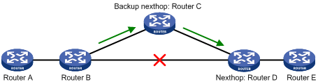
In Figure 23, after you enable FRR on Router B, OSPF automatically calculates or designates a backup next hop when a link failure is detected. Packets are directed to the backup next hop. At the same time, OSPF calculates the shortest path based on the new network topology, and forwards packets over the path after routing convergence.
You can either configure OSPF FRR to calculate a backup next hop automatically, or designate a backup next hop by using a routing policy.
Configuration prerequisites
Before you configure OSPF FRR, complete the following tasks:
· Configure network layer addresses for interfaces to ensure IP connectivity between neighboring nodes.
· Enable OSPF.
Configuration guidelines
· Do not use FRR and BFD at the same time. Otherwise, FRR might fail to take effect.
· Do not use the fast-reroute auto command together with the commands vlink-peer, sham-link, enable traffic-adjustment, and enable traffic-adjustment advertise (in MPLS Command Reference).
Configuring OSPF FRR to automatically calculate a backup next hop
|
Step |
Command |
Remarks |
|
1. Enter system view. |
system-view |
N/A |
|
2. Configure the source address of echo packets. |
bfd echo-source-ip ip-address |
Not configured by default. |
|
3. Enter OSPF view. |
ospf [ process-id | router-id router-id | vpn-instance vpn-instance-name ] * |
N/A |
|
4. Enable OSPF FRR to automatically calculate a backup next hop. |
fast-reroute auto [ abr-only ] |
Not configured by default. If abr-only is specified, the route to the ABR is selected as the backup path. |
Configuring OSPF FRR to designate a backup next hop with a routing policy
Before you configure this task, you need to use the apply fast-reroute backup-interface command to specify a backup next hop in the routing policy to be referenced. For more information about the apply fast-reroute backup-interface command and routing policy configurations, see "Configuring routing policies."
To configure OSPF FRR:
|
Step |
Command |
Remarks |
|
1. Enter system view. |
system-view |
N/A |
|
2. Configure the source address of echo packets. |
bfd echo-source-ip ip-address |
Not configured by default. |
|
3. Enter OSPF view. |
ospf [ process-id | router-id router-id | vpn-instance vpn-instance-name ] * |
N/A |
|
4. Enable OSPF FRR to designate a backup next hop by using a routing policy. |
fast-reroute route-policy route-policy-name |
Not configured by default. |
Configuring OSPF Graceful Restart
· IETF standard GR—Uses Opaque LSAs to implement GR.
· Non IETF standard GR—Uses link local signaling (LLS) to advertise GR capability and uses out of band synchronization to synchronize the LSDB.
A device can act as a GR restarter and GR helper at the same time.
Configuring the OSPF GR restarter
You can configure the IETF standard or non IETF standard OSPF GR restarter.
|
|
IMPORTANT: Do not configure OSPF NSR on a device that acts as GR restarter. |
Configuring the IETF standard OSPF GR restarter
|
Step |
Command |
Remarks |
|
1. Enter system view. |
system-view |
N/A |
|
2. Enable OSPF and enter its view. |
ospf [ process-id | router-id router-id | vpn-instance vpn-instance-name ] * |
N/A |
|
3. Enable opaque LSA advertisement capability. |
opaque-capability enable |
Disabled by default. |
|
4. Enable the IETF standard Graceful Restart capability. |
graceful-restart ietf |
Disabled by default. |
|
5. Configure the Graceful Restart interval. |
graceful-restart interval timer |
Optional. 120 seconds by default. |
Configuring the non-IETF standard OSPF GR restarter
|
Step |
Command |
Remarks |
|
1. Enter system view. |
system-view |
N/A |
|
2. Enable OSPF and enter its view. |
ospf [ process-id | router-id router-id | vpn-instance vpn-instance-name ] * |
N/A |
|
3. Enable the link-local signaling capability. |
enable link-local-signaling |
Disabled by default. |
|
4. Enable the out-of-band re-synchronization capability. |
enable out-of-band-resynchronization |
Disabled by default. |
|
5. Enable non-IETF standard Graceful Restart capability for OSPF. |
graceful-restart [ nonstandard ] |
Disabled by default. |
|
6. Configure Graceful Restart interval for OSPF. |
graceful-restart interval timer |
Optional. 120 seconds by default. |
Configuring the OSPF GR helper
You can configure the IETF standard or non IETF standard OSPF GR helper.
Configuring the IETF standard OSPF GR helper
|
Step |
Command |
Remarks |
|
1. Enter system view. |
system-view |
N/A |
|
2. Enable OSPF and enter its view. |
ospf [ process-id | router-id router-id | vpn-instance vpn-instance-name ] * |
N/A |
|
3. Enable opaque LSA reception and advertisement. |
opaque-capability enable |
Not enabled by default. |
|
4. Configure the neighbors for which the router can serve as a GR helper. |
graceful-restart help { acl-number | prefix prefix-list } |
Optional. The router can serve as a GR helper for any OSPF neighbor by default. |
Configuring the non-IETF standard OSPF GR helper
|
Step |
Command |
Remarks |
|
1. Enter system view. |
system-view |
N/A |
|
2. Enable OSPF and enter its view. |
ospf [ process-id | router-id router-id | vpn-instance vpn-instance-name ] * |
N/A |
|
3. Enable the link-local signaling capability. |
enable link-local-signaling |
Disabled by default. |
|
4. Enable the out-of-band re-synchronization capability. |
enable out-of-band-resynchronization |
Disabled by default. |
|
5. Configure the neighbors for which the router can serve as a GR helper. |
graceful-restart help { acl-number | prefix prefix-list } |
Optional. The router can serve as a GR helper for any OSPF neighbor by default. |
Triggering OSPF Graceful Restart
Performing an active/standby switchover on a device, or performing the following configuration on an OSPF switch, will trigger OSPF Graceful Restart.
To trigger OSPF Graceful Restart, perform the following command in user view:
|
Task |
Command |
|
Trigger OSPF Graceful Restart. |
reset ospf [ process-id ] process graceful-restart |
Configuring OSPF NSR
With OSPF NSR, the standby MPU backs up the link state information from the active MPU. Upon an active/standby switchover, the link state information can recover automatically and the routes can be regenerated without tearing down the adjacencies or impacting other services.
GR requires the cooperation of neighboring devices to recover routing information. NSR does not require that, and is more popular in practice.
|
|
NOTE: A device enabled with OSPF NSR cannot act as the GR restarter. |
To enable OSPF NSR:
|
Step |
Command |
Remarks |
|
1. Enter system view. |
system-view |
N/A |
|
2. Enable OSPF NSR. |
ospf non-stop-routing |
Optional. Disabled by default. |
Configuring BFD for OSPF
OSPF supports the following BFD detection methods:
· Bidirectional control detection, which requires BFD configuration to be made on both OSPF routers on the link.
· Single-hop echo detection, which requires BFD configuration to be made on one OSPF router on the link.
Configuring bidirectional control detection
Both ends of a BFD session must be on the same network segment and in the same area. One network segment can only belong to one area.
To enable BFD bidirectional control detection on an OSPF interface:
|
Step |
Command |
Remarks |
|
1. Enter system view. |
system-view |
N/A |
|
2. Enter interface view. |
interface interface-type interface-number |
N/A |
|
3. Enable BFD bidirectional control bidirectional detection on the interface. |
ospf bfd enable |
Not enabled by default. |
Configuring single-hop echo detection
|
Step |
Command |
Remarks |
|
1. Enter system view. |
system-view |
N/A |
|
2. Configure the source address of echo packets. |
bfd echo-source-ip ip-address |
Not configured by default. |
|
3. Enter interface view. |
interface interface-type interface-number |
N/A |
|
4. Enable single-hop echo detection on the interface. |
ospf bfd enable echo |
Not enabled by default. |
Displaying and maintaining OSPF
|
Task |
Command |
Remarks |
|
Display OSPF brief information. |
display ospf [ process-id ] brief [ | { begin | exclude | include } regular-expression ] |
Available in any view. |
|
Display OSPF statistics. |
display ospf [ process-id ] cumulative [ | { begin | exclude | include } regular-expression ] |
Available in any view. |
|
Display Link State Database information. |
display ospf [ process-id ] lsdb [ brief | [ { ase | router | network | summary | asbr | nssa | opaque-link | opaque-area | opaque-as } [ link-state-id ] ] [ originate-router advertising-router-id | self-originate ] ] [ | { begin | exclude | include } regular-expression ] |
Available in any view. |
|
Display OSPF neighbor information. |
display ospf [ process-id ] peer [ verbose ] [ interface-type interface-number ] [ neighbor-id ] [ | { begin | exclude | include } regular-expression ] |
Available in any view. |
|
Display neighbor statistics of OSPF areas. |
display ospf [ process-id ] peer statistics [ | { begin | exclude | include } regular-expression ] |
Available in any view. |
|
Display next hop information. |
display ospf [ process-id ] nexthop [ | { begin | exclude | include } regular-expression ] |
Available in any view. |
|
Display routing table information. |
display ospf [ process-id ] routing [ interface interface-type interface-number ] [ nexthop nexthop-address ] [ | { begin | exclude | include } regular-expression ] |
Available in any view. |
|
Display virtual link information. |
display ospf [ process-id ] vlink [ | { begin | exclude | include } regular-expression ] |
Available in any view. |
|
Display OSPF request queue information. |
display ospf [ process-id ] request-queue [ interface-type interface-number ] [ neighbor-id ] [ | { begin | exclude | include } regular-expression ] |
Available in any view. |
|
Display OSPF retransmission queue information. |
display ospf [ process-id ] retrans-queue [ interface-type interface-number ] [ neighbor-id ] [ | { begin | exclude | include } regular-expression ] |
Available in any view. |
|
Display OSPF ABR and ASBR information. |
display ospf [ process-id ] abr-asbr [ | { begin | exclude | include } regular-expression ] |
Available in any view. |
|
Display OSPF interface information. |
display ospf [ process-id ] interface [ all | interface-type interface-number ] [ | { begin | exclude | include } regular-expression ] |
Available in any view. |
|
Display OSPF error information. |
display ospf [ process-id ] error [ | { begin | exclude | include } regular-expression ] |
Available in any view. |
|
Display OSPF ASBR summarization information. |
display ospf [ process-id ] asbr-summary [ ip-address { mask | mask-length } ] [ | { begin | exclude | include } regular-expression ] |
Available in any view. |
|
Display the global router ID. |
display router id [ | { begin | exclude | include } regular-expression ] |
Available in any view. |
|
Clear OSPF statistics. |
reset ospf [ process-id ] counters [ neighbor [ interface-type interface-number ] [ router-id ] ] |
Available in user view. |
|
Reset an OSPF process. |
reset ospf [ process-id ] process [ graceful-restart ] |
Available in user view. |
|
Re-enable OSPF route redistribution. |
reset ospf [ process-id ] redistribution |
Available in user view. |
OSPF configuration examples
These configuration examples only cover OSPF configuration related commands.
By default, Ethernet, VLAN, and aggregate interfaces are down. Before configuring these interfaces, bring them up by using the undo shutdown command.
Configuring basic OSPF
Network requirements
As shown in Figure 24, all switches run OSPF. The AS is split into three areas, where Switch A and Switch B act as ABRs to forward routing information between areas.
After configuration, all switches can learn routes to every network segment in the AS.
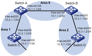
Configuration procedure
1. Configure IP addresses for interfaces. (Details not shown.)
2. Configure basic OSPF:
# Configure Switch A.
<SwitchA> system-view
[SwitchA] ospf
[SwitchA-ospf-1] area 0
[SwitchA-ospf-1-area-0.0.0.0] network 10.1.1.0 0.0.0.255
[SwitchA-ospf-1-area-0.0.0.0] quit
[SwitchA-ospf-1] area 1
[SwitchA-ospf-1-area-0.0.0.1] network 10.2.1.0 0.0.0.255
[SwitchA-ospf-1-area-0.0.0.1] quit
[SwitchA-ospf-1] quit
# Configure Switch B.
<SwitchB> system-view
[SwitchB] ospf
[SwitchB-ospf-1] area 0
[SwitchB-ospf-1-area-0.0.0.0] network 10.1.1.0 0.0.0.255
[SwitchB-ospf-1-area-0.0.0.0] quit
[SwitchB-ospf-1] area 2
[SwitchB-ospf-1-area-0.0.0.2] network 10.3.1.0 0.0.0.255
[SwitchB-ospf-1-area-0.0.0.2] quit
[SwitchB-ospf-1] quit
# Configure Switch C.
<SwitchC> system-view
[SwitchC] ospf
[SwitchC-ospf-1] area 1
[SwitchC-ospf-1-area-0.0.0.1] network 10.2.1.0 0.0.0.255
[SwitchC-ospf-1-area-0.0.0.1] network 10.4.1.0 0.0.0.255
[SwitchC-ospf-1-area-0.0.0.1] quit
[SwitchC-ospf-1] quit
# Configure Switch D.
<SwitchD> system-view
[SwitchD] ospf
[SwitchD-ospf-1] area 2
[SwitchD-ospf-1-area-0.0.0.2] network 10.3.1.0 0.0.0.255
[SwitchD-ospf-1-area-0.0.0.2] network 10.5.1.0 0.0.0.255
[SwitchD-ospf-1-area-0.0.0.2] quit
[SwitchD-ospf-1] quit
3. Verify the configuration:
# Display information about neighbors on Switch A.
[SwitchA] display ospf peer verbose
OSPF Process 1 with Router ID 10.2.1.1
Neighbors
Area 0.0.0.0 interface 10.1.1.1(Vlan-interface100)'s neighbors
Router ID: 10.3.1.1 Address: 10.1.1.2 GR State: Normal
State: Full Mode: Nbr is Master Priority: 1
DR: 10.1.1.1 BDR: 10.1.1.2 MTU: 0
Dead timer due in 37 sec
Neighbor is up for 06:03:59
Authentication Sequence: [ 0 ]
Neighbor state change count: 5
Neighbors
Area 0.0.0.1 interface 10.2.1.1(Vlan-interface200)'s neighbors
Router ID: 10.4.1.1 Address: 10.2.1.2 GR State: Normal
State: Full Mode: Nbr is Master Priority: 1
DR: 10.2.1.1 BDR: 10.2.1.2 MTU: 0
Dead timer due in 32 sec
Neighbor is up for 06:03:12
Authentication Sequence: [ 0 ]
Neighbor state change count: 5
# Display OSPF routing information on Switch A.
[SwitchA] display ospf routing
OSPF Process 1 with Router ID 10.2.1.1
Routing Tables
Routing for Network
Destination Cost Type NextHop AdvRouter Area
10.2.1.0/24 10 Transit 10.2.1.1 10.2.1.1 0.0.0.1
10.3.1.0/24 4 Inter 10.1.1.2 10.3.1.1 0.0.0.0
10.4.1.0/24 13 Stub 10.2.1.2 10.4.1.1 0.0.0.1
10.5.1.0/24 14 Inter 10.1.1.2 10.3.1.1 0.0.0.0
10.1.1.0/24 2 Transit 10.1.1.1 10.2.1.1 0.0.0.0
Total Nets: 5
Intra Area: 3 Inter Area: 2 ASE: 0 NSSA: 0
# Display the LSDB on Switch A.
[SwitchA] display ospf lsdb
OSPF Process 1 with Router ID 10.2.1.1
Link State Database
Area: 0.0.0.0
Type LinkState ID AdvRouter Age Len Sequence Metric
Router 10.2.1.1 10.2.1.1 1069 36 80000012 0
Router 10.3.1.1 10.3.1.1 780 36 80000011 0
Network 10.1.1.1 10.2.1.1 1069 32 80000010 0
Sum-Net 10.5.1.0 10.3.1.1 780 28 80000003 12
Sum-Net 10.2.1.0 10.2.1.1 1069 28 8000000F 10
Sum-Net 10.3.1.0 10.3.1.1 780 28 80000014 2
Sum-Net 10.4.1.0 10.2.1.1 769 28 8000000F 13
Area: 0.0.0.1
Type LinkState ID AdvRouter Age Len Sequence Metric
Router 10.2.1.1 10.2.1.1 769 36 80000012 0
Router 10.4.1.1 10.4.1.1 1663 48 80000012 0
Network 10.2.1.1 10.2.1.1 769 32 80000010 0
Sum-Net 10.5.1.0 10.2.1.1 769 28 80000003 14
Sum-Net 10.3.1.0 10.2.1.1 1069 28 8000000F 4
Sum-Net 10.1.1.0 10.2.1.1 1069 28 8000000F 2
Sum-Asbr 10.3.1.1 10.2.1.1 1069 28 8000000F 2
# Display OSPF routing information on Switch D.
[SwitchD] display ospf routing
OSPF Process 1 with Router ID 10.5.1.1
Routing Tables
Routing for Network
Destination Cost Type NextHop AdvRouter Area
10.2.1.0/24 22 Inter 10.3.1.1 10.3.1.1 0.0.0.2
10.3.1.0/24 10 Transit 10.3.1.2 10.3.1.1 0.0.0.2
10.4.1.0/24 25 Inter 10.3.1.1 10.3.1.1 0.0.0.2
10.5.1.0/24 10 Stub 10.5.1.1 10.5.1.1 0.0.0.2
10.1.1.0/24 12 Inter 10.3.1.1 10.3.1.1 0.0.0.2
Total Nets: 5
Intra Area: 2 Inter Area: 3 ASE: 0 NSSA: 0
# On Switch D, ping the IP address 10.4.1.1 to test connectivity.
[SwitchD] ping 10.4.1.1
PING 10.4.1.1: 56 data bytes, press CTRL_C to break
Reply from 10.4.1.1: bytes=56 Sequence=1 ttl=255 time=3 ms
Reply from 10.4.1.1: bytes=56 Sequence=2 ttl=255 time=2 ms
Reply from 10.4.1.1: bytes=56 Sequence=3 ttl=255 time=2 ms
Reply from 10.4.1.1: bytes=56 Sequence=4 ttl=255 time=2 ms
Reply from 10.4.1.1: bytes=56 Sequence=5 ttl=255 time=3 ms
--- 10.4.1.1 ping statistics ---
5 packet(s) transmitted
5 packet(s) received
0.00% packet loss
round-trip min/avg/max = 2/2/3 ms
Configuring OSPF route redistribution
Network requirements
All the switches Figure 25 run OSPF, and the AS is divided into three areas.
Switch A and Switch B act as ABRs to forward routes between areas.
Switch C is configured as an ASBR to redistribute external routes (static routes). Routing information is propagated correctly in the AS.
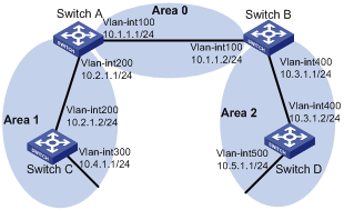
Configuration procedure
1. Configure IP addresses for interfaces. (Details not shown.)
2. Configure basic OSPF (see "Configuring basic OSPF").
3. Configure OSPF to redistribute routes:
# On Switch C, configure a static route destined for network 3.1.2.0/24.
<SwitchC> system-view
[SwitchC] ip route-static 3.1.2.1 24 10.4.1.2
# On Switch C, configure OSPF to redistribute static routes.
[SwitchC] ospf 1
[SwitchC-ospf-1] import-route static
4. Verify the configuration:
# Display the ABR/ASBR information of Switch D.
<SwitchD> display ospf abr-asbr
OSPF Process 1 with Router ID 10.5.1.1
Routing Table to ABR and ASBR
Type Destination Area Cost Nexthop RtType
Intra 10.3.1.1 0.0.0.2 10 10.3.1.1 ABR
Inter 10.4.1.1 0.0.0.2 22 10.3.1.1 ASBR
# Display the OSPF routing table on Switch D.
<SwitchD> display ospf routing
OSPF Process 1 with Router ID 10.5.1.1
Routing Tables
Routing for Network
Destination Cost Type NextHop AdvRouter Area
10.2.1.0/24 22 Inter 10.3.1.1 10.3.1.1 0.0.0.2
10.3.1.0/24 10 Transit 10.3.1.2 10.3.1.1 0.0.0.2
10.4.1.0/24 25 Inter 10.3.1.1 10.3.1.1 0.0.0.2
10.5.1.0/24 10 Stub 10.5.1.1 10.5.1.1 0.0.0.2
10.1.1.0/24 12 Inter 10.3.1.1 10.3.1.1 0.0.0.2
Routing for ASEs
Destination Cost Type Tag NextHop AdvRouter
3.1.2.0/24 1 Type2 1 10.3.1.1 10.4.1.1
Total Nets: 6
Intra Area: 2 Inter Area: 3 ASE: 1 NSSA: 0
Configuring OSPF to advertise a summary route
Network requirements
· Configure OSPF on Switch A and Switch B in AS 200.
· Configure OSPF on Switch C, Switch D, and Switch E in AS 100.
· Configure an EBGP connection between Switch B and Switch C. Configure Switch B and Switch C to redistribute OSPF routes and direct routes into BGP and BGP routes into OSPF.
· Configure Switch B to advertise only summary route 10.0.0.0/8 to Switch A.
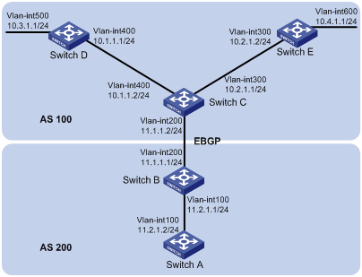
Configuration procedure
1. Configure IP addresses for interfaces. (Details not shown.)
2. Configure basic OSPF:
# Configure Switch A.
<SwitchA> system-view
[SwitchA] ospf
[SwitchA-ospf-1] area 0
[SwitchA-ospf-1-area-0.0.0.0] network 11.2.1.0 0.0.0.255
[SwitchA-ospf-1-area-0.0.0.0] quit
[SwitchA-ospf-1] quit
# Configure Switch B.
<SwitchB> system-view
[SwitchB] ospf
[SwitchB-ospf-1] area 0
[SwitchB-ospf-1-area-0.0.0.0] network 11.2.1.0 0.0.0.255
[SwitchB-ospf-1-area-0.0.0.0] quit
[SwitchB-ospf-1] quit
# Configure Switch C.
<SwitchC> system-view
[SwitchC] ospf
[SwitchC-ospf-1] area 0
[SwitchC-ospf-1-area-0.0.0.0] network 10.1.1.0 0.0.0.255
[SwitchC-ospf-1-area-0.0.0.0] network 10.2.1.0 0.0.0.255
[SwitchC-ospf-1-area-0.0.0.0] quit
[SwitchC-ospf-1] quit
# Configure Switch D.
<SwitchD> system-view
[SwitchD] ospf
[SwitchD-ospf-1] area 0
[SwitchD-ospf-1-area-0.0.0.0] network 10.1.1.0 0.0.0.255
[SwitchD-ospf-1-area-0.0.0.0] network 10.3.1.0 0.0.0.255
[SwitchD-ospf-1-area-0.0.0.0] quit
# Configure Switch E.
<SwitchE> system-view
[SwitchE] ospf
[SwitchE-ospf-1] area 0
[SwitchE-ospf-1-area-0.0.0.0] network 10.2.1.0 0.0.0.255
[SwitchE-ospf-1-area-0.0.0.0] network 10.4.1.0 0.0.0.255
[SwitchE-ospf-1-area-0.0.0.0] quit
[SwitchE-ospf-1] quit
3. Configure BGP to redistribute OSPF routes and direct routes:
# Configure Switch B.
[SwitchB] bgp 200
[SwitchB-bgp] peer 11.1.1.2 as 100
[SwitchB-bgp] import-route ospf
[SwitchB-bgp] import-route direct
[SwitchB-bgp] quit
# Configure Switch C.
[SwitchC] bgp 100
[SwitchC-bgp] peer 11.1.1.1 as 200
[SwitchC-bgp] import-route ospf
[SwitchC-bgp] import-route direct
[SwitchC-bgp] quit
4. Configure Switch B and Switch C to redistribute BGP routes into OSPF:
# Configure Switch B.
[SwitchB] ospf
[SwitchB-ospf-1] import-route bgp
# Configure Switch C.
[SwitchC] ospf
[SwitchC-ospf-1] import-route bgp
# Display the OSPF routing table on Switch A.
[SwitchA] display ip routing-table
Routing Tables: Public
Destinations : 8 Routes : 8
Destination/Mask Proto Pre Cost NextHop Interface
10.1.1.0/24 O_ASE 150 1 11.2.1.1 Vlan100
10.2.1.0/24 O_ASE 150 1 11.2.1.1 Vlan100
10.3.1.0/24 O_ASE 150 1 11.2.1.1 Vlan100
10.4.1.0/24 O_ASE 150 1 11.2.1.1 Vlan100
11.2.1.0/24 Direct 0 0 11.2.1.2 Vlan100
11.2.1.2/32 Direct 0 0 127.0.0.1 InLoop0
127.0.0.0/8 Direct 0 0 127.0.0.1 InLoop0
127.0.0.1/32 Direct 0 0 127.0.0.1 InLoop0
5. Configure route summarization:
Configure summary route 10.0.0.0/8 on Switch B and advertise it.
[SwitchB-ospf-1] asbr-summary 10.0.0.0 8
# Display the OSPF routing table on Switch A.
[SwitchA] display ip routing-table
Routing Tables: Public
Destinations : 5 Routes : 5
Destination/Mask Proto Pre Cost NextHop Interface
10.0.0.0/8 O_ASE 150 2 11.2.1.1 Vlan100
11.2.1.0/24 Direct 0 0 11.2.1.2 Vlan100
11.2.1.2/32 Direct 0 0 127.0.0.1 InLoop0
127.0.0.0/8 Direct 0 0 127.0.0.1 InLoop0
127.0.0.1/32 Direct 0 0 127.0.0.1 InLoop0
The output shows that only summary route 10.0.0.0/8 exists.
Configuring an OSPF stub area
Network requirements
Figure 27 shows an AS split into three areas, where all switches run OSPF. Switch A and Switch B act as ABRs to forward routing information between areas. Switch D acts as the ASBR to redistribute routes (static routes).
Configure Area 1 as a Stub area, reducing LSAs to this area without affecting route reachability.
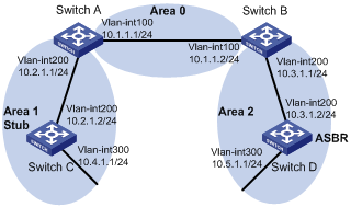
Configuration procedure
1. Configure IP addresses for interfaces. (Details not shown.)
2. Configure basic OSPF (see "Configuring basic OSPF").
3. Configure route redistribution:
Configure Switch D to redistribute static routes.
<SwitchD> system-view
[SwitchD] ip route-static 3.1.2.1 24 10.5.1.2
[SwitchD] ospf
[SwitchD-ospf-1] import-route static
[SwitchD-ospf-1] quit
# Display ABR/ASBR information on Switch C.
<SwitchC> display ospf abr-asbr
OSPF Process 1 with Router ID 10.4.1.1
Routing Table to ABR and ASBR
Type Destination Area Cost Nexthop RtType
Intra 10.2.1.1 0.0.0.1 3 10.2.1.1 ABR
Inter 10.3.1.1 0.0.0.1 5 10.2.1.1 ABR
Inter 10.5.1.1 0.0.0.1 7 10.2.1.1 ASBR
# Display OSPF routing table information on Switch C.
<SwitchC> display ospf routing
OSPF Process 1 with Router ID 10.4.1.1
Routing Tables
Routing for Network
Destination Cost Type NextHop AdvRouter Area
10.2.1.0/24 3 Transit 10.2.1.2 10.2.1.1 0.0.0.1
10.3.1.0/24 7 Inter 10.2.1.1 10.2.1.1 0.0.0.1
10.4.1.0/24 3 Stub 10.4.1.1 10.4.1.1 0.0.0.1
10.5.1.0/24 17 Inter 10.2.1.1 10.2.1.1 0.0.0.1
10.1.1.0/24 5 Inter 10.2.1.1 10.2.1.1 0.0.0.1
Routing for ASEs
Destination Cost Type Tag NextHop AdvRouter
3.1.2.0/24 1 Type2 1 10.2.1.1 10.5.1.1
Total Nets: 6
Intra Area: 2 Inter Area: 3 ASE: 1 NSSA: 0
The output shows that because Switch C resides in a normal OSPF area, its routing table contains an external route.
4. Configure Area 1 as a stub area:
# Configure Switch A.
<SwitchA> system-view
[SwitchA] ospf
[SwitchA-ospf-1] area 1
[SwitchA-ospf-1-area-0.0.0.1] stub
[SwitchA-ospf-1-area-0.0.0.1] quit
[SwitchA-ospf-1] quit
# Configure Switch C.
<SwitchA> system-view
[SwitchC] ospf
[SwitchC-ospf-1] area 1
[SwitchC-ospf-1-area-0.0.0.1] stub
[SwitchC-ospf-1-area-0.0.0.1] quit
[SwitchC-ospf-1] quit
# Display OSPF routing information on Switch C
[SwitchC] display ospf routing
OSPF Process 1 with Router ID 10.4.1.1
Routing Tables
Routing for Network
Destination Cost Type NextHop AdvRouter Area
0.0.0.0/0 4 Inter 10.2.1.1 10.2.1.1 0.0.0.1
10.2.1.0/24 3 Transit 10.2.1.2 10.2.1.1 0.0.0.1
10.3.1.0/24 7 Inter 10.2.1.1 10.2.1.1 0.0.0.1
10.4.1.0/24 3 Stub 10.4.1.1 10.4.1.1 0.0.0.1
10.5.1.0/24 17 Inter 10.2.1.1 10.2.1.1 0.0.0.1
10.1.1.0/24 5 Inter 10.2.1.1 10.2.1.1 0.0.0.1
Total Nets: 6
Intra Area: 2 Inter Area: 4 ASE: 0 NSSA: 0
When Switch C resides in the stub area, a default route replaces the external route.
# Filter Type-3 LSAs out of the stub area.
[SwitchA] ospf
[SwitchA-ospf-1] area 1
[SwitchA-ospf-1-area-0.0.0.1] stub no-summary
[SwitchA-ospf-1-area-0.0.0.1] quit
# Display OSPF routing information on Switch C.
[SwitchC] display ospf routing
OSPF Process 1 with Router ID 10.4.1.1
Routing Tables
Routing for Network
Destination Cost Type NextHop AdvRouter Area
0.0.0.0/0 4 Inter 10.2.1.1 10.2.1.1 0.0.0.1
10.2.1.0/24 3 Transit 10.2.1.2 10.4.1.1 0.0.0.1
10.4.1.0/24 3 Stub 10.4.1.1 10.4.1.1 0.0.0.1
Total Nets: 3
Intra Area: 2 Inter Area: 1 ASE: 0 NSSA: 0
The output shows that routing entries on the stub router are further reduced, containing only one default external route.
Configuring an OSPF NSSA area
Network requirements
Figure 28 shows an AS split into three areas, where all switches run OSPF. Switch A and Switch B act as ABRs to forward routing information between areas.
Configure Area 1 as an NSSA area and configure Switch C as the ASBR to redistribute static routes into the AS.
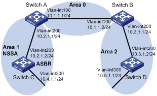
Configuration procedure
1. Configure IP addresses for interfaces.
2. Configure basic OSPF (see "Configuring basic OSPF").
3. Configure Area 1 as an NSSA area:
# Configure Switch A.
<SwitchA> system-view
[SwitchA] ospf
[SwitchA-ospf-1] area 1
[SwitchA-ospf-1-area-0.0.0.1] nssa default-route-advertise no-summary
[SwitchA-ospf-1-area-0.0.0.1] quit
[SwitchA-ospf-1] quit
# Configure Switch C.
<SwitchA> system-view
[SwitchC] ospf
[SwitchC-ospf-1] area 1
[SwitchC-ospf-1-area-0.0.0.1] nssa
[SwitchC-ospf-1-area-0.0.0.1] quit
[SwitchC-ospf-1] quit
|
|
NOTE: · To allow Switch C in the NSSA area to reach other areas within the AS, you must provide the keyword default-route-advertise for the nssa command on Switch A (an ABR) so that Switch C can obtain a default route. · Configuring the nssa command with the keyword no-summary on Switch A can reduce the routing table size on NSSA switches. On other NSSA switches, you only need to configure the nssa command. |
# Display OSPF routing information on Switch C.
[SwitchC] display ospf routing
OSPF Process 1 with Router ID 10.4.1.1
Routing Tables
Routing for Network
Destination Cost Type NextHop AdvRouter Area
0.0.0.0/0 65536 Inter 10.2.1.1 10.2.1.1 0.0.0.1
10.2.1.0/24 65535 Transit 10.2.1.2 10.4.1.1 0.0.0.1
10.4.1.0/24 3 Stub 10.4.1.1 10.4.1.1 0.0.0.1
Total Nets: 3
Intra Area: 2 Inter Area: 1 ASE: 0 NSSA: 0
4. Configure route redistribution:
# Configure Switch C to redistribute static routes.
[SwitchC] ip route-static 3.1.3.1 24 10.4.1.2
[SwitchC] ospf
[SwitchC-ospf-1] import-route static
[SwitchC-ospf-1] quit
# Display OSPF routing information on Switch D.
<SwitchD> display ospf routing
OSPF Process 1 with Router ID 10.5.1.1
Routing Tables
Routing for Network
Destination Cost Type NextHop AdvRouter Area
10.2.1.0/24 22 Inter 10.3.1.1 10.3.1.1 0.0.0.2
10.3.1.0/24 10 Transit 10.3.1.2 10.3.1.1 0.0.0.2
10.4.1.0/24 25 Inter 10.3.1.1 10.3.1.1 0.0.0.2
10.5.1.0/24 10 Stub 10.5.1.1 10.5.1.1 0.0.0.2
10.1.1.0/24 12 Inter 10.3.1.1 10.3.1.1 0.0.0.2
Routing for ASEs
Destination Cost Type Tag NextHop AdvRouter
3.1.3.0/24 1 Type2 1 10.3.1.1 10.2.1.1
Total Nets: 6
Intra Area: 2 Inter Area: 3 ASE: 1 NSSA: 0
The output shows an external route imported from the NSSA area on Switch D.
Configuring OSPF DR election
Network requirements
In Figure 29, OSPF Switches A, B, C, and D reside on the same network segment.
Configure Switch A as the DR and configure Switch C as the BDR.
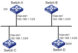
Configuration procedure
1. Configure IP addresses for interfaces. (Details not shown.)
2. Configure basic OSPF:
# Configure Switch A.
<SwitchA> system-view
[SwitchA] router id 1.1.1.1
[SwitchA] ospf
[SwitchA-ospf-1] area 0
[SwitchA-ospf-1-area-0.0.0.0] network 192.168.1.0 0.0.0.255
[SwitchA-ospf-1-area-0.0.0.0] quit
[SwitchA-ospf-1] quit
# Configure Switch B.
<SwitchB> system-view
[SwitchB] router id 2.2.2.2
[SwitchB] ospf
[SwitchB-ospf-1] area 0
[SwitchB-ospf-1-area-0.0.0.0] network 192.168.1.0 0.0.0.255
[SwitchB-ospf-1-area-0.0.0.0] quit
[SwitchB-ospf-1] quit
# Configure Switch C.
<SwitchC> system-view
[SwitchC] router id 3.3.3.3
[SwitchC] ospf
[SwitchC-ospf-1] area 0
[SwitchC-ospf-1-area-0.0.0.0] network 192.168.1.0 0.0.0.255
[SwitchC-ospf-1-area-0.0.0.0] quit
[SwitchC-ospf-1] quit
# Configure Switch D.
<SwitchD> system-view
[SwitchD] router id 4.4.4.4
[SwitchD] ospf
[SwitchD-ospf-1] area 0
[SwitchD-ospf-1-area-0.0.0.0] network 192.168.1.0 0.0.0.255
[SwitchD-ospf-1-area-0.0.0.0] quit
[SwitchD-ospf-1] return
# Display OSPF neighbor information on Switch A.
<SwitchD> display ospf peer verbose
OSPF Process 1 with Router ID 1.1.1.1
Neighbors
Area 0.0.0.0 interface 192.168.1.1(Vlan-interface1)'s neighbors
Router ID: 2.2.2.2 Address: 192.168.1.2 GR State: Normal
State: 2-Way Mode: None Priority: 1
DR: 192.168.1.4 BDR: 192.168.1.3 MTU: 0
Dead timer due in 38 sec
Neighbor is up for 00:01:31
Authentication Sequence: [ 0 ]
Router ID: 3.3.3.3 Address: 192.168.1.3 GR State: Normal
State: Full Mode: Nbr is Master Priority: 1
DR: 192.168.1.4 BDR: 192.168.1.3 MTU: 0
Dead timer due in 31 sec
Neighbor is up for 00:01:28
Authentication Sequence: [ 0 ]
Router ID: 4.4.4.4 Address: 192.168.1.4 GR State: Normal
State: Full Mode: Nbr is Master Priority: 1
DR: 192.168.1.4 BDR: 192.168.1.3 MTU: 0
Dead timer due in 31 sec
Neighbor is up for 00:01:28
Authentication Sequence: [ 0 ]
Switch D becomes the DR and Switch C is the BDR.
3. Configure router priorities on interfaces:
# Configure Switch A.
[SwitchA] interface vlan-interface 1
[SwitchA-Vlan-interface1] ospf dr-priority 100
[SwitchA-Vlan-interface1] quit
# Configure Switch B.
[SwitchB] interface vlan-interface 1
[SwitchB-Vlan-interface1] ospf dr-priority 0
[SwitchB-Vlan-interface1] quit
# Configure Switch C.
[SwitchC] interface vlan-interface 1
[SwitchC-Vlan-interface1] ospf dr-priority 2
[SwitchC-Vlan-interface1] quit
# Display neighbor information on Switch D.
[SwitchD] display ospf peer verbose
OSPF Process 1 with Router ID 4.4.4.4
Neighbors
Area 0.0.0.0 interface 192.168.1.4(Vlan-interface1)'s neighbors
Router ID: 1.1.1.1 Address: 192.168.1.1 GR State: Normal
State: Full Mode:Nbr is Slave Priority: 100
DR: 192.168.1.4 BDR: 192.168.1.3 MTU: 0
Dead timer due in 31 sec
Neighbor is up for 00:11:17
Authentication Sequence: [ 0 ]
Router ID: 2.2.2.2 Address: 192.168.1.2 GR State: Normal
State: Full Mode:Nbr is Slave Priority: 0
DR: 192.168.1.4 BDR: 192.168.1.3 MTU: 0
Dead timer due in 35 sec
Neighbor is up for 00:11:19
Authentication Sequence: [ 0 ]
Router ID: 3.3.3.3 Address: 192.168.1.3 GR State: Normal
State: Full Mode:Nbr is Slave Priority: 2
DR: 192.168.1.4 BDR: 192.168.1.3 MTU: 0
Dead timer due in 33 sec
Neighbor is up for 00:11:15
Authentication Sequence: [ 0 ]
The DR and BDR are not changed, because the priority settings do not take effect immediately.
4. Restart OSPF process:
# Restart the OSPF process of Switch D.
<SwitchD> reset ospf 1 process
Warning : Reset OSPF process? [Y/N]:y
# Display neighbor information on Switch D.
<SwitchD> display ospf peer verbose
OSPF Process 1 with Router ID 4.4.4.4
Neighbors
Area 0.0.0.0 interface 192.168.1.4(Vlan-interface1)'s neighbors
Router ID: 1.1.1.1 Address: 192.168.1.1 GR State: Normal
State: Full Mode: Nbr is Slave Priority: 100
DR: 192.168.1.1 BDR: 192.168.1.3 MTU: 0
Dead timer due in 39 sec
Neighbor is up for 00:01:40
Authentication Sequence: [ 0 ]
Router ID: 2.2.2.2 Address: 192.168.1.2 GR State: Normal
State: 2-Way Mode: None Priority: 0
DR: 192.168.1.1 BDR: 192.168.1.3 MTU: 0
Dead timer due in 35 sec
Neighbor is up for 00:01:44
Authentication Sequence: [ 0 ]
Router ID: 3.3.3.3 Address: 192.168.1.3 GR State: Normal
State: Full Mode: Nbr is Slave Priority: 2
DR: 192.168.1.1 BDR: 192.168.1.3 MTU: 0
Dead timer due in 39 sec
Neighbor is up for 00:01:41
Authentication Sequence: [ 0 ]
Switch A becomes the DR and Switch C is the BDR.
The full neighbor state means that Switch D has established the adjacency with the neighbor. The 2-way neighbor state means that the two switches are neither the DR nor the BDR, and they do not exchange LSAs.
# Display OSPF interface information.
[SwitchA] display ospf interface
OSPF Process 1 with Router ID 1.1.1.1
Interfaces
Area: 0.0.0.0
IP Address Type State Cost Pri DR BDR
192.168.1.1 Broadcast DR 1 100 192.168.1.1 192.168.1.3
[SwitchB] display ospf interface
OSPF Process 1 with Router ID 2.2.2.2
Interfaces
Area: 0.0.0.0
IP Address Type State Cost Pri DR BDR
192.168.1.2 Broadcast DROther 1 0 192.168.1.1 192.168.1.3
The interface state DROther means the interface is not the DR or BDR.
Configuring OSPF virtual links
Network requirements
In Figure 30, Area 2 has no direct connection to Area 0, and Area 1 acts as the Transit Area to connect Area 2 to Area 0 through a configured virtual link between Switch B and Switch C.
After configuration, Switch B can learn routes to Area 2.
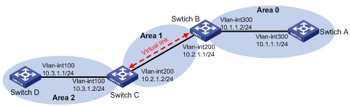
Configuration procedure
1. Configure IP addresses for interfaces. (Details not shown.)
2. Configure basic OSPF:
# Configure Switch A.
<SwitchA> system-view
[SwitchA] ospf 1 router-id 1.1.1.1
[SwitchA-ospf-1] area 0
[SwitchA-ospf-1-area-0.0.0.0] network 10.1.1.0 0.0.0.255
[SwitchA-ospf-1-area-0.0.0.0] quit
# Configure Switch B.
<SwitchB> system-view
[SwitchB] ospf 1 router-id 2.2.2.2
[SwitchB-ospf-1] area 0
[SwitchB-ospf-1-area-0.0.0.0] network 10.1.1.0 0.0.0.255
[SwitchB-ospf-1-area-0.0.0.0] quit
[SwitchB-ospf-1] area 1
[SwitchB–ospf-1-area-0.0.0.1] network 10.2.1.0 0.0.0.255
[SwitchB–ospf-1-area-0.0.0.1] quit
[SwitchB-ospf-1] quit
# Configure Switch C.
<SwitchC> system-view
[SwitchC] ospf 1 router-id 3.3.3.3
[SwitchC-ospf-1] area 1
[SwitchC-ospf-1-area-0.0.0.1] network 10.2.1.0 0.0.0.255
[SwitchC-ospf-1-area-0.0.0.1] quit
[SwitchC-ospf-1] area 2
[SwitchC–ospf-1-area-0.0.0.2] network 10.3.1.0 0.0.0.255
[SwitchC–ospf-1-area-0.0.0.2] quit
[SwitchC-ospf-1] quit
# Configure Switch D.
<SwitchD> system-view
[SwitchD] ospf 1 router-id 4.4.4.4
[SwitchD-ospf-1] area 2
[SwitchD-ospf-1-area-0.0.0.2] network 10.3.1.0 0.0.0.255
[SwitchD-ospf-1-area-0.0.0.2] quit
# Display the OSPF routing table on Switch B.
[SwitchB] display ospf routing
OSPF Process 1 with Router ID 2.2.2.2
Routing Tables
Routing for Network
Destination Cost Type NextHop AdvRouter Area
10.2.1.0/24 2 Transit 10.2.1.1 3.3.3.3 0.0.0.1
10.1.1.0/24 2 Transit 10.1.1.2 2.2.2.2 0.0.0.0
Total Nets: 2
Intra Area: 2 Inter Area: 0 ASE: 0 NSSA: 0
Area 0 has no direct connection to Area 2, so the routing table of Switch B has no route to Area 2.
3. Configure a virtual link:
# Configure Switch B.
[SwitchB] ospf
[SwitchB-ospf-1] area 1
[SwitchB-ospf-1-area-0.0.0.1] vlink-peer 3.3.3.3
[SwitchB-ospf-1-area-0.0.0.1] quit
[SwitchB-ospf-1] quit
# Configure Switch C.
[SwitchC] ospf 1
[SwitchC-ospf-1] area 1
[SwitchC-ospf-1-area-0.0.0.1] vlink-peer 2.2.2.2
[SwitchC-ospf-1-area-0.0.0.1] quit
# Display the OSPF routing table on Switch B.
[SwitchB] display ospf routing
OSPF Process 1 with Router ID 2.2.2.2
Routing Tables
Routing for Network
Destination Cost Type NextHop AdvRouter Area
10.2.1.0/24 2 Transit 10.2.1.1 3.3.3.3 0.0.0.1
10.3.1.0/24 5 Inter 10.2.1.2 3.3.3.3 0.0.0.0
10.1.1.0/24 2 Transit 10.1.1.2 2.2.2.2 0.0.0.0
Total Nets: 3
Intra Area: 2 Inter Area: 1 ASE: 0 NSSA: 0
Switch B has learned the route 10.3.1.0/24 to Area 2.
OSPF Graceful Restart configuration example
Network requirements
Switch A, Switch B and Switch C that belong to the same autonomous system and the same OSPF routing domain are GR capable.
Switch A acts as the non-IETF standard GR restarter, whereas Switch B and Switch C are the GR helpers and re-synchronize their LSDB with Switch A through OOB communication of GR.
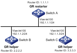
Configuration procedure
1. Configure IP addresses for interfaces. (Details not shown.)
2. Configure basic OSPF:
# Configure Switch A
<SwitchA> system-view
[SwitchA] router id 1.1.1.1
[SwitchA] ospf 100
[SwitchA-ospf-100] area 0
[SwitchA-ospf-100-area-0.0.0.0] network 192.1.1.0 0.0.0.255
[SwitchA-ospf-100-area-0.0.0.0] quit
# Configure Switch B
<SwitchB> system-view
[SwitchB] router id 2.2.2.2
[SwitchB] ospf 100
[SwitchB-ospf-100] area 0
[SwitchB-ospf-100-area-0.0.0.0] network 192.1.1.0 0.0.0.255
[SwitchB-ospf-100-area-0.0.0.0] quit
# Configure Switch C
<SwitchC> system-view
[SwitchC] router id 3.3.3.3
[SwitchC] ospf 100
[SwitchC-ospf-100] area 0
[SwitchC-ospf-100-area-0.0.0.0] network 192.1.1.0 0.0.0.255
[SwitchC-ospf-100-area-0.0.0.0] quit
3. Configure OSPF GR:
# Configure Switch A as the non-IETF standard OSPF GR restarter: enable the link-local signaling capability, the out-of-band re-synchronization capability, and non IETF standard Graceful Restart capability for OSPF process 100.
[SwitchA-ospf-100] enable link-local-signaling
[SwitchA-ospf-100] enable out-of-band-resynchronization
[SwitchA-ospf-100] graceful-restart
[SwitchA-ospf-100] return
# Configure Switch B as the GR helper: enable the link-local signaling capability and the out-of-band re-synchronization capability for OSPF process 100.
[SwitchB-ospf-100] enable link-local-signaling
[SwitchB-ospf-100] enable out-of-band-resynchronization
# Configure Switch C as the GR helper: enable the link-local signaling capability and the out-of-band re-synchronization capability for OSPF process 100.
[SwitchC-ospf-100] enable link-local-signaling
[SwitchC-ospf-100] enable out-of-band-resynchronization
4. Verify the configuration:
# After the configurations on Switch A, Switch B, and Switch C are complete and the switches are running steadily, enable OSPF Graceful Restart event debugging and then restart the OSPF process using GR on Switch A.
<SwitchA> debugging ospf event graceful-restart
<SwitchA> terminal monitor
<SwitchA> terminal debugging
<SwitchA> reset ospf 100 process graceful-restart
Warning : Reset OSPF process? [Y/N]:y
%Dec 12 09:36:12:500 2006 SwitchA RM/3/RMLOG:OSPF-NBRCHANGE: Process 100, Neighbour
192.1.1.1(Vlan100) from Full to Down
OSPF 100: Intf 192.1.1.1 Rcv InterfaceDown State BackupDR -> Down.
OSPF 100 nonstandard GR Started for OSPF Router
OSPF 100 notify RM that OSPF process will enter GR.
OSPF 100 created GR wait timer, timeout interval is 40(s).
OSPF 100 created GR Interval timer,timeout interval is 120(s).
OSPF 100: Intf 192.1.1.1 Rcv InterfaceUp State Down -> Waiting.
OSPF 100: Intf 192.1.1.1 Rcv BackupSeen State Waiting -> BackupDR.
OSPF 100 created OOB Progress timer for neighbor 192.1.1.2.
OSPF 100 restarted OOB Progress timer for neighbor 192.1.1.2.
OSPF 100 restarted OOB Progress timer for neighbor 192.1.1.2.
%Oct 22 09:36:12:566 2008 SwitchA RM/3/RMLOG:OSPF-NBRCHANGE: Process 100, Neighbour
192.1.1.2(Vlan100) from Loading to Full
OSPF 100 restarted OOB Progress timer for neighbor 192.1.1.2.
OSPF 100 deleted OOB Progress timer for neighbor 192.1.1.2.
OSPF 100 Gr Wait Timeout timer fired.
OSPF 100 deleted GR wait timer.
OSPF 100 deleted GR Interval timer.
OSPF 100 GR Completed for OSPF Router
OSPF 100 notified RM that OSPF process left GR.
RM notified that all protocol left GR.
OSPF 100 started flushing STALE LSA after all protocol left GR.
OSPF 100: Flush Stale Area LSAs
OSPF 100: Start Flush Stale ASE + NSSA LSAs
OSPF 100: End Flush Stale ASE + NSSA LSAs
Switch A completes GR with the help of Switch B.
OSPF NSR configuration example
Network requirements
As shown in Figure 32, Switch S, Switch A, and Switch B belong to the same OSPF routing domain. Enable OSPF NSR on Switch S to ensure correct routing when an active/standby switchover occurs on Switch S.
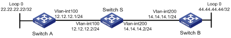
Configuration procedure
1. Configure IP addresses and subnet masks for interfaces on the switches. (Details not shown.)
2. Configure OSPF on the switches to make sure that Switch S, Switch A, and Switch B can communicate with each other at Layer 3 and dynamic route update can be implemented among them with OSPF. (Details not shown.)
3. Enable OSPF NSR on Switch S.
<SwitchS> system-view
[SwitchS] ospf non-stop-routing
4. Verify the configuration:
After Switch S establishes neighbor relationships with Switch A and Switch B, they start to exchange routing information. After network convergence, perform an active/standby switchover on Switch S. During the switchover period, use the display ospf peer command to check the neighbor relationship between Switch A and Switch S and between Switch B and Switch S; use the display ospf routing command to check if there are routes from Switch A to the loopback interface on Switch B and from Switch B to the loopback interface on Switch A.
# Perform an active/standby switchover on Switch S.
[SwitchS] slave switchover enable
[SwitchS] slave switchover
Caution!!! Confirm to switch slave to master? [Y/N]:y
# Display OSPF neighbors and routes on Switch A.
<SwitchA> display ospf peer
OSPF Process 1 with Router ID 192.168.1.40
Neighbor Brief Information
Area: 0.0.0.0
Router ID Address Pri Dead-Time Interface State
192.168.1.41 12.12.12.2 1 40 Vlan100 Full/BDR
<SwitchA> display ospf routing
OSPF Process 1 with Router ID 192.168.1.40
Routing Tables
Routing for Network
Destination Cost Type NextHop AdvRouter Area
44.44.44.44/32 2 Stub 12.12.12.2 44.44.44.44 0.0.0.0
14.14.14.0/24 2 Transit 12.12.12.2 192.168.1.41 0.0.0.0
22.22.22.22/32 0 Stub 22.22.22.22 192.168.1.40 0.0.0.0
12.12.12.0/24 1 Transit 12.12.12.1 192.168.1.40 0.0.0.0
Total Nets: 4
Intra Area: 4 Inter Area: 0 ASE: 0 NSSA: 0
# Display OSPF neighbors and routes on Switch B.
<SwitchB> display ospf peer
OSPF Process 1 with Router ID 44.44.44.44
Neighbor Brief Information
Area: 0.0.0.0
Router ID Address Pri Dead-Time Interface State
192.168.1.41 14.14.14.2 1 33 Vlan200 Full/DR
<SwitchB> display ospf routing
OSPF Process 1 with Router ID 44.44.44.44
Routing Tables
Routing for Network
Destination Cost Type NextHop AdvRouter Area
44.44.44.44/32 0 Stub 44.44.44.44 44.44.44.44 0.0.0.0
14.14.14.0/24 1 Transit 14.14.14.1 192.168.1.41 0.0.0.0
22.22.22.22/32 2 Stub 14.14.14.2 192.168.1.40 0.0.0.0
12.12.12.0/24 2 Transit 14.14.14.2 192.168.1.40 0.0.0.0
Total Nets: 4
Intra Area: 4 Inter Area: 0 ASE: 0 NSSA: 0
The output shows that when an active/standby switchover occurs on Switch S, the neighbor relationships and routing information on Switch A and Switch B have not changed and the traffic from Switch A to Switch B has not been impacted.
Configuring route filtering
Network requirements
In Figure 33, all the switches in the network run OSPF. The AS is divided into three areas. Switch A and Switch B work as ABRs.
Configure Switch C as an ASBR to redistribute external routes (static routes), and configure a filter policy on Switch C to filter out redistributed route 3.1.3.0/24.
Configure a routing policy on Switch A to filter route 10.5.1.0/24.
Configuration procedure
1. Configure IP addresses for interfaces. (Details not shown.)
2. Configure basic OSPF (see "Configuring basic OSPF").
3. Configure OSPF to redistribute routes:
# On Switch C, configure a static route destined for network 3.1.1.0/24.
<SwitchC> system-view
[SwitchC] ip route-static 3.1.1.0 24 10.4.1.2
# On Switch C, configure a static route destined for network 3.1.2.0/24.
[SwitchC] ip route-static 3.1.2.0 24 10.4.1.2
# On Switch C, configure a static route destined for network 3.1.3.0/24.
[SwitchC] ip route-static 3.1.3.0 24 10.4.1.2
# On Switch C, configure OSPF to redistribute static routes.
[SwitchC] ospf 1
[SwitchC-ospf-1] import-route static
[SwitchC-ospf-1] quit
# Display the OSPF routing table on Switch A.
<SwitchA> display ip routing-table
Routing Tables: Public
Destinations : 12 Routes : 12
Destination/Mask Proto Pre Cost NextHop Interface
3.1.1.0/24 O_ASE 150 1 10.2.1.2 Vlan200
3.1.2.0/24 O_ASE 150 1 10.2.1.2 Vlan200
3.1.3.0/24 O_ASE 150 1 10.2.1.2 Vlan200
10.1.1.0/24 Direct 0 0 10.1.1.1 Vlan200
10.1.1.1/32 Direct 0 0 127.0.0.1 InLoop0
10.2.1.0/24 Direct 0 0 10.2.1.1 Vlan200
10.2.1.1/32 Direct 0 0 127.0.0.1 InLoop0
10.3.1.0/24 OSPF 10 4 10.1.1.2 Vlan100
10.4.1.0/24 OSPF 10 13 10.2.1.2 Vlan200
10.5.1.0/24 OSPF 10 14 10.1.1.2 Vlan100
127.0.0.0/8 Direct 0 0 127.0.0.1 InLoop0
127.0.0.1/32 Direct 0 0 127.0.0.1 InLoop0
4. On Switch C, filter out route 3.1.3.0/24:
# Configure the IPv4 prefix list.
[SwitchC] ip ip-prefix prefix1 index 1 deny 3.1.3.0 24
[SwitchC] ip ip-prefix prefix1 index 2 permit 3.1.1.0 24
[SwitchC] ip ip-prefix prefix1 index 3 permit 3.1.2.0 24
# Reference the prefix list to filter out route 3.1.3.0/24.
[SwitchC] ospf 1
[SwitchC-ospf-1] filter-policy ip-prefix prefix1 export static
# Display the OSPF routing table on Switch A.
<SwitchA> display ip routing-table
Routing Tables: Public
Destinations : 11 Routes : 11
Destination/Mask Proto Pre Cost NextHop Interface
3.1.1.0/24 O_ASE 150 1 10.2.1.2 Vlan200
3.1.2.0/24 O_ASE 150 1 10.2.1.2 Vlan200
10.1.1.0/24 Direct 0 0 10.1.1.1 Vlan100
10.1.1.1/32 Direct 0 0 127.0.0.1 InLoop0
10.2.1.0/24 Direct 0 0 10.2.1.1 Vlan200
10.2.1.1/32 Direct 0 0 127.0.0.1 InLoop0
10.3.1.0/24 OSPF 10 4 10.1.1.2 Vlan100
10.4.1.0/24 OSPF 10 13 10.2.1.2 Vlan200
10.5.1.0/24 OSPF 10 14 10.1.1.2 Vlan100
127.0.0.0/8 Direct 0 0 127.0.0.1 InLoop0
127.0.0.1/32 Direct 0 0 127.0.0.1 InLoop0
The route destined for network 3.1.3.0/24 is filtered out.
5. On Switch A, filter out the route 10.5.1.1/24:
# Configure the ACL on Switch A.
<SwitchA> system-view
[SwitchA] acl number 2000
[SwitchA-acl-basic-2000] rule 0 deny source 10.5.1.0 0.0.0.255
[SwitchA-acl-basic-2000] rule 1 permit source any
[SwitchA-acl-basic-2000] quit
# Use the ACL to filter route 10.5.1.0/24.
[SwitchA] ospf 1
[SwitchA-ospf-1] filter-policy 2000 import
[SwitchA-ospf-1] quit
# Display the OSPF routing table on Switch A.
[SwitchA] display ip routing-table
Routing Tables: Public
Destinations : 10 Routes : 10
Destination/Mask Proto Pre Cost NextHop Interface
3.1.1.0/24 O_ASE 150 1 10.2.1.2 Vlan200
3.1.2.0/24 O_ASE 150 1 10.2.1.2 Vlan200
10.1.1.0/24 Direct 0 0 10.1.1.1 Vlan100
10.1.1.1/32 Direct 0 0 127.0.0.1 InLoop0
10.2.1.0/24 Direct 0 0 10.2.1.1 Vlan200
10.2.1.1/32 Direct 0 0 127.0.0.1 InLoop0
10.3.1.0/24 OSPF 10 4 10.1.1.2 Vlan100
10.4.1.0/24 OSPF 10 13 10.2.1.2 Vlan200
127.0.0.0/8 Direct 0 0 127.0.0.1 InLoop0
127.0.0.1/32 Direct 0 0 127.0.0.1 InLoop0
The route destined for 10.5.1.1/24 is filtered out.
Configuring OSPF FRR
Network requirements
Switch S, Switch A, and Switch D belong to the same OSPF domain. They are interconnected through OSPF, as shown in Figure 34. When Link A between Switch S and Switch D fails, traffic is immediately switched to Link B.
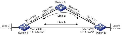
Configuration procedure
1. Configure the IP addresses and subnet masks for interfaces on the switches. (Details not shown.)
2. Configure OSPF on the switches to make sure that Switch S, Switch A, and Switch D can communicate with each other at Layer 3 and dynamic route update can be implemented among them with OSPF. (Details not shown.)
3. Configure OSPF FRR:
You can enable OSPF FRR to either automatically calculate a backup next hop, or designate a backup next hop by using a routing policy.
¡ (Method 1.) Enable OSPF FRR to automatically calculate the backup next hop:
# Configure Switch S.
<SwitchS> system-view
[SwitchS] bfd echo-source-ip 1.1.1.1
[SwitchS] ospf 1
[SwitchS-ospf-1] fast-reroute auto
[SwitchS-ospf-1] quit
# Configure Switch D.
<SwitchD> system-view
[SwitchD] bfd echo-source-ip 4.4.4.4
[SwitchD] ospf 1
[SwitchD-ospf-1] fast-reroute auto
[SwitchD-ospf-1] quit
¡ (Method 2.) Enable OSPF FRR to designate a backup next hop by using a routing policy:
# Configure Switch S.
<SwitchS> system-view
[SwitchS] bfd echo-source-ip 1.1.1.1
[SwitchS] ip ip-prefix abc index 10 permit 4.4.4.4 32
[SwitchS] route-policy frr permit node 10
[SwitchS-route-policy] if-match ip-prefix abc
[SwitchS-route-policy] apply fast-reroute backup-interface vlan-interface 100 backup-nexthop 12.12.12.2
[SwitchS-route-policy] quit
[SwitchS] ospf 1
[SwitchS-ospf-1] fast-reroute route-policy frr
[SwitchS-ospf-1] quit
# Configure Switch D.
<SwitchD> system-view
[SwitchD] bfd echo-source-ip 4.4.4.4
[SwitchD] ip ip-prefix abc index 10 permit 1.1.1.1 32
[SwitchD] route-policy frr permit node 10
[SwitchD-route-policy] if-match ip-prefix abc
[SwitchD-route-policy] apply fast-reroute backup-interface vlan-interface 101 backup-nexthop 24.24.24.2
[SwitchD-route-policy] quit
[SwitchD] ospf 1
[SwitchD-ospf-1] fast-reroute route-policy frr
[SwitchD-ospf-1] quit
4. Verify the configuration:
# Display route 4.4.4.4/32 on Switch S to view the backup next hop information.
[SwitchS] display ip routing-table 4.4.4.4 verbose
Routing Table : Public
Summary Count : 1
Destination: 4.4.4.4/32
Protocol: OSPF Process ID: 1
Preference: 10 Cost: 1
IpPrecedence: QosLcId:
NextHop: 13.13.13.2 Interface: Vlan-interface200
BkNextHop: 12.12.12.2 BkInterface: Vlan-interface100
RelyNextHop: 0.0.0.0 Neighbor : 0.0.0.0
Tunnel ID: 0x0 Label: NULL
BKTunnel ID: 0x0 BKLabel: NULL
State: Active Adv Age: 00h01m27s
Tag: 0
# Display route 1.1.1.1/32 on Switch D to view the backup next hop information.
[SwitchD] display ip routing-table 1.1.1.1 verbose
Routing Table : Public
Summary Count : 1
Destination: 1.1.1.1/32
Protocol: OSPF Process ID: 1
Preference: 10 Cost: 1
IpPrecedence: QosLcId:
NextHop: 13.13.13.1 Interface: Vlan-interface200
BkNextHop: 24.24.24.2 BkInterface: Vlan-interface101
RelyNextHop: 0.0.0.0 Neighbor : 0.0.0.0
Tunnel ID: 0x0 Label: NULL
BKTunnel ID: 0x0 BKLabel: NULL
State: Active Adv Age: 00h01m27s
Tag: 0
Configuring BFD for OSPF
Network requirements
As shown in Figure 35, OSPF is enabled on Switch A, Switch B and Switch C that are reachable to each other at the network layer.
After the link over which Switch A and Switch B communicate through a Layer 2 switch fails, BFD can quickly detect the failure and notify OSPF of the failure. Then Switch A and Switch B communicate through Switch C.

|
Device |
Interface |
IP address |
Device |
Interface |
IP address |
|
Switch A |
Vlan-int10 |
192.168.0.102/24 |
Switch B |
Vlan-int10 |
192.168.0.100/24 |
|
|
Vlan-int11 |
10.1.1.102/24 |
|
Vlan-int13 |
13.1.1.1/24 |
|
Switch C |
Vlan-int11 |
10.1.1.100/24 |
|
|
|
|
|
Vlan-int13 |
13.1.1.2/24 |
|
|
|
Configuration procedure
1. Configure IP addresses for interfaces. (Details not shown.)
2. Configure basic OSPF:
# Configure Switch A.
<SwitchA> system-view
[SwitchA] ospf
[SwitchA-ospf-1] area 0
[SwitchA-ospf-1-area-0.0.0.0] network 10.1.1.0 0.0.0.255
[SwitchA-ospf-1-area-0.0.0.0] network 192.168.0.0 0.0.0.255
[SwitchA-ospf-1-area-0.0.0.0] network 121.1.1.0 0.0.0.255
[SwitchA-ospf-1-area-0.0.0.0] quit
[SwitchA-ospf-1] quit
[SwitchA] interface vlan 11
[SwitchA-Vlan-interface11] ospf cost 2
[SwitchA-Vlan-interface11] quit
# Configure Switch B.
<SwitchB> system-view
[SwitchB] ospf
[SwitchB-ospf-1] area 0
[SwitchB-ospf-1-area-0.0.0.0] network 192.168.0.0 0.0.0.255
[SwitchB-ospf-1-area-0.0.0.0] network 13.1.1.0 0.0.0.255
[SwitchB-ospf-1-area-0.0.0.0] network 120.1.1.0 0.0.0.255
[SwitchB-ospf-1-area-0.0.0.0] quit
[SwitchB-ospf-1] quit
[SwitchB] interface vlan-interface 13
[SwitchB-Vlan-interface13] ospf cost 2
[SwitchB-Vlan-interface13] quit
# Configure Switch C.
<SwitchC> system-view
[SwitchC] ospf
[SwitchC-ospf-1] area 0
[SwitchC-ospf-1-area-0.0.0.0] network 10.1.1.0 0.0.0.255
[SwitchC-ospf-1-area-0.0.0.0] network 13.1.1.0 0.0.0.255
[SwitchC-ospf-1-area-0.0.0.0] quit
[SwitchC-ospf-1] quit
3. Configure BFD:
# Enable BFD on Switch A and configure BFD parameters.
[SwitchA] bfd session init-mode active
[SwitchA] interface vlan-interface 10
[SwitchA-Vlan-interface10] ospf bfd enable
[SwitchA-Vlan-interface10] bfd min-transmit-interval 500
[SwitchA-Vlan-interface10] bfd min-receive-interval 500
[SwitchA-Vlan-interface10] bfd detect-multiplier 7
[SwitchA-Vlan-interface10] quit
[SwitchA] quit
# Enable BFD on Switch B and configure BFD parameters.
[SwitchB] bfd session init-mode active
[SwitchB] interface vlan-interface 10
[SwitchB-Vlan-interface10] ospf bfd enable
[SwitchB-Vlan-interface10] bfd min-transmit-interval 500
[SwitchB-Vlan-interface10] bfd min-receive-interval 500
[SwitchB-Vlan-interface10] bfd detect-multiplier 6
4. Verify the configuration:
The following operations are performed on Switch A. The operations on Switch B and Switch C are similar, and thus are not shown.
# Display the BFD information on Switch A.
<SwitchA> display bfd session
Total Session Num: 1 Init Mode: Active
Session Working Under Ctrl Mode:
LD/RD SourceAddr DestAddr State Holdtime Interface
3/1 192.168.0.102 192.168.0.100 Up 1700ms vlan10
# Display routes destined for 120.1.1.0/24 on Switch A.
<SwitchA> display ip routing-table 120.1.1.0 verbose
Routing Table : Public
Summary Count : 1
Destination: 120.1.1.0/24
Protocol: OSPF Process ID: 1
Preference: 0 Cost: 2
IpPrecedence: QosLcId:
NextHop: 192.168.0.100 Interface: Vlan-interface10
BkNextHop: 0.0.0.0 BkInterface:
RelyNextHop: 0.0.0.0 Neighbor : 0.0.0.0
Tunnel ID: 0x0 Label: NULL
BKTunnel ID: 0x0 BKLabel: NULL
State: Active Adv Age: 00h58m10s
Tag: 0
The output shows that Switch A communicates with Switch B through VLAN-interface 10. Then the link over VLAN-interface 10 fails.
# Enable BFD debugging on Switch A.
<SwitchA> debugging bfd scm
<SwitchA> debugging bfd event
<SwitchA> debugging ospf event
<SwitchA> terminal debugging
%Nov 12 18:34:48:823 2005 SwitchA BFD/5/LOG: Sess[192.168.0.102/192.168.0.100, vlan10], Sta : UP->DOWN, Diag: 1
%Nov 12 18:34:48:824 2005 SwitchA RM/4/RMLOG:OSPF-NBRCHANGE: Process 1, Neighbour 192.168.0.102 (vlan10) from Full to Down
*0.50673825 SwitchA BFD/8/SCM:Sess[192.168.0.102/192.168.0.100, vlan10],Oper: Reset
*0.50673825 SwitchA BFD/8/EVENT:Send sess-down Msg, [Src: 192.168.0.102, Dst: 192.168.0.100, vlan10] Protocol: OSPF
*0.50673826 SwitchA RM/7/RMDEBUG:OSPF-BFD: Message Type rcv BFD down, Connect Type direct-connect, Src IP Address 192.168.0.102, Src IFIndex 5, Dst IP Address 192.168.0.100
*0.50673827 SwitchA RM/7/RMDEBUG:OSPF-BFD: Message Type delete session, Connect Type direct-connect, Src IP Address 192.168.0.102, Src IFIndex 5, Dst IP Address 192.168.0.100
OSPF 1: Nbr 192.168.0.100 Rcv KillNbr State Full -> Down.
*0.50673829 SwitchA BFD/8/EVENT:Receive Delete-sess, [Src: 192.168.0.102, Dst: 192.168.0.100, vlan10], Direct, Proto:OSPF
*0.50673830 SwitchA BFD/8/SCM:Sess[192.168.0.102/192.168.0.100, vlan10], Oper: Del application(OSPF)
*0.50673831 SwitchA BFD/8/SCM:No application in session, delete session[192.168.0.102/192.168.0.100, vlan10]
*0.50673831 SwitchA BFD/8/SCM:Sess[192.168.0.102/192.168.0.100, vlan10], Oper: Delete
*0.50673832 SwitchA BFD/8/SCM:Delete send-packet timer
*0.50673833 SwitchA BFD/8/SCM:Delete session entry
*0.50673833 SwitchA BFD/8/SCM:Delete session from IP hash table
*0.50673834 SwitchA BFD/8/SCM:Delete session from bfd interface
*0.50673834 SwitchA BFD/8/SCM:No session under bfd-int[vlan10] with default configuration, delete bfd-if
*0.50673835 SwitchA BFD/8/SCM:Bfd-if[vlan10], Oper: Delete
*0.50673840 SwitchA BFD/8/SCM:No bfd session exists, stop receiving any bfd packets
The output shows that Switch A can quickly detect the changes on Switch B.
# Display the BFD information on Switch A.
<SwitchA> display bfd session
The output shows that Switch A has deleted the BFD session on VLAN-interface 10 to Switch B and displays no output.
# Display routes destined for 120.1.1.0/24 on Switch A.
<SwitchA> display ip routing-table 120.1.1.0 verbose
Routing Table : Public
Summary Count : 1
Destination: 120.1.1.0/24
Protocol: OSPF Process ID: 1
Preference: 10 Cost: 4
IpPrecedence: QosLcId:
NextHop: 10.1.1.100 Interface: Vlan-interface11
BkNextHop: 0.0.0.0 BkInterface:
RelyNextHop: 0.0.0.0 Neighbor : 0.0.0.0
Tunnel ID: 0x0 Label: NULL
BKTunnel ID: 0x0 BKLabel: NULL
State: Active Adv Age: 00h58m10s
Tag: 0
The output shows that Switch A communicates with Switch B through VLAN-interface 11.
Troubleshooting OSPF configuration
No OSPF neighbor relationship established
Symptom
No OSPF neighbor relationship can be established.
Analysis
If the physical link and lower layer protocols work well, check OSPF parameters configured on interfaces. Two neighbors must have the same parameters, such as the area ID, network segment, and mask (a P2P or virtual link might have different network segments and masks).
Solution
1. Display OSPF neighbor information by using the display ospf peer command.
2. Display OSPF interface information by using the display ospf interface command.
3. Ping the neighbor router's IP address to check connectivity.
4. Check OSPF timers. The dead interval on an interface must be at least four times the hello interval.
5. On an NBMA network, use the peer ip-address command to manually specify the neighbor.
6. At least one connected interface must have a router priority higher than 0 on an NBMA or a broadcast network.
Incorrect routing information
Symptom
OSPF cannot find routes to other areas.
Analysis
The backbone area must maintain connectivity to all other areas. If a router connects to more than one area, at least one area must be connected to the backbone. The backbone cannot be configured as a Stub area.
In a Stub area, all routers cannot receive external routes, and all interfaces connected to the Stub area must belong to the Stub area.
Solution
1. Use the display ospf peer command to display neighbors.
2. Use the display ospf interface command to display OSPF interface information.
3. Use the display ospf lsdb command to display the Link State Database to check its integrity.
4. Display information about area configuration using the display current-configuration configuration ospf command. If more than two areas are configured, at least one area is connected to the backbone.
5. In a stub area, all routers attached are configured with the stub command. In an NSSA area, all routers attached are configured with the nssa command.
6. If a virtual link is configured, use the display ospf vlink command to check the state of the virtual link.