- Table of Contents
- Related Documents
-
| Title | Size | Download |
|---|---|---|
| 01-Text | 1.39 MB |
Contents
Accessories provided with the AP
Determining the installation position
Connecting the AP to the network
Checking the network connection for the fit AP
Checking the network connection for the fat AP
Logging in through the console port
Setting up the configuration environment
Logging in through the console port
Logging in through Telnet or web
The H3C WA2610i-GN Access Point has integrated antennas, and also supports external antennas. The WA2610i-GN can serve as a fit AP to cooperate with wireless switches or access controllers to provide wireless access for WLAN users. All configuration tasks are configured on the wireless switches or access controllers. The WA2610i-GN can also operate as a fat AP to provide wireless access for WLAN users.
Figure 1 Deployment of the AP on hotspots (fit AP)
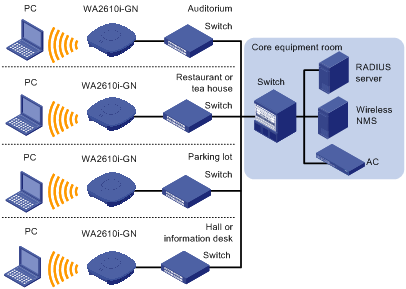
Figure 2 Deployment of the AP on hotspots (fat AP)
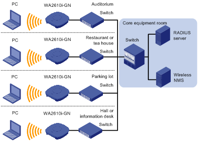
Table 1 Basic configuration
|
Dimensions (H × W × D) |
Weight |
Max. power |
Enclosure |
Protocol |
Power supply |
|
160 × 160 × 50 mm (6.30 × 6.30 × 1.97 in) |
328 g (11.57 oz) |
12.95 W |
Plastic |
802.11b/g/n |
Local power supply + 802.3af |
Safety recommendations
|
|
WARNING! Only qualified personnel can install and remove a WA2610i-GN and its accessories. You must read all safety instructions supplied with the access points before installation and operation. |
To avoid possible bodily injury and equipment damage, read the following safety recommendations before you install a WA2610i-GN. Note that the recommendations do not cover every possible hazardous condition.
· Take adequate safety measures to avoid bodily injury and access point damage.
· Make sure that the ground is dry and flat and anti-slip measures are in place.
· Keep the chassis clean and dust-free.
· Do not place the access point in a moist area and avoid liquid surrounding the access point.
· Keep the chassis and installation tools away from walkways.
Accessories provided with the AP
The following accessories are provided with the AP:
|
|
|
|
|
MAC address label |
Wall anchor kit |
Console cable (provided with the fat AP only) |
|
|
|
|
|
T-rail holder mounting screw |
Hex-head bolt, washer, and nut |
Wall-mounting bracket |
|
|
|
|
|
Rubber feet |
|
|

|
|
NOTE: Antennas, power adapter, and power cable are user-supplied. |
|
|
CAUTION: The WA2610i-GN is usually installed on a high position, such as a wall or ceiling, so the maintenance personnel cannot log in from the console port to maintain and debug the AP. H3C recommends that you log in to the AP through the console port to perform remote login (Telnet or web login) configuration, or log in through Telnet or web by using the default login information before you install the AP. For more information about logging in to the AP, see “Logging in to the fat AP.” |
Figure 3 Installation flowchart
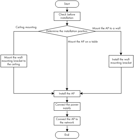
Check before installation
Before you install an AP, check the following:
· Connect the power cord and connect the AP to the network. Check the LED status to make sure that the AP can operate properly. For more information about AP LEDs, see “Appendix LEDs and ports.”
· Check that cabling has been completed.
· The WA2610i-GN supports 802.3af-compliant PoE. To achieve the best performance, H3C recommends that you adopt GE connection to the power device.
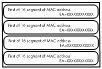
· Record the MAC address and serial number of the AP (marked on the rear of the AP) for future use.
Determining the installation position
Determine the installation position by observing the following principles:
· Leave as few obstacles (such as wall) as possible between APs and clients.
· Install APs away from electronic devices (such as microwave ovens) that may generate radio frequency (RF) noise.
· Install APs in a place where they will not hinder people’s daily work and life.
· Do not install APs in a place where water seeping, water soaking, and condensing occur. Prevent water or moisture from entering the APs.
|
|
CAUTION: If part of the power line is routed outdoors, use a power strip with lightning protection (user supplied) to connect the power cord of the AP to the power line to protect the AP from being damaged by lightning strikes. |
Installing the AP
|
|
NOTE: The WA2610i-GN has integrated antennas. When you install the AP, determine whether external antennas (user-supplied) are needed. Installing external antennas is not covered in this document. |
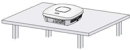
Mounting the AP on a table
|
|
WARNING! Do not place the WA2610i-GN on any metal surface. Place it on a place where there are no obstacles and good signal strength is available. |
1. To mount the AP on a table, attach the rubber feet supplied with the AP to the rear of the AP.
Figure 4 Attach the rubber feet
2. Place the AP on the table with the rubber feet facing downwards.
Figure 5 Mounting the AP on a table
Mounting the AP on a wall
To mount the AP on a wall, you need a wall-mounting bracket and wall anchor kit.
Figure 6 Screw hole locations and sizes (in mm)
|
(1) Hook |
(2) Mounting hole |
|
(3) Clip |
(4) Mounting clip |
|
|
CAUTION: Connect the AP to the network by using an Ethernet cable, and then install the AP to the wall-mounting bracket when you mount the AP on a wall. |
To mount the AP on a wall:
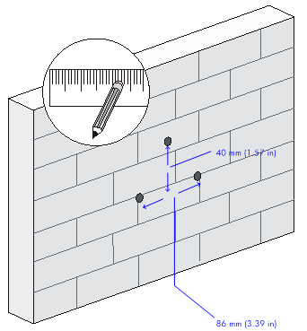
1. Use the wall-mounting bracket as a template to mark the locations of the mounting holes on the bracket. Drill three 5 mm (0.2 in) diameter holes at the mounting hole locations you marked.
Figure 7 Drill holes on the wall
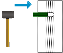
2. Insert a wall anchor into each mounting hole, and tap the wall anchor with a rubber hammer until it is all flush with the wall surface.
Figure 8 Fix the anchor to the wall
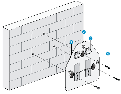
3. Align the holes in the wall-mounting bracket with the anchors and insert screws through the installation holes into the wall anchors.
4. Adjust the position of the wall-mounting bracket and tighten the screws.
Figure 9 Install the wall-mounting bracket
|
(1) Wall anchor |
(2) Wall-mounting bracket |
(3) Hook |
|
(4) Clip |
(5) Screw |
|
5. Connect the AP to the network by using an Ethernet cable.
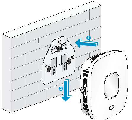
6. Align the mounting keyhole on the rear of the AP over the hook on the wall-mounting bracket.
7. Mount the AP on the hook on the wall-mounting bracket. See callout 1 in Figure 10.
8. Pull down the AP with force until it clicks into place. See callout 2 in Figure 10.
Figure 10 Fix the AP onto the wall-mounting bracket
Mounting the AP on a ceiling
|
|
NOTE: · The ceiling tiles must be less than 18 mm (0.71 in) thick, and the ceiling can bear a weight of at least 5 kg (11.02 lb). · Do not use this method to mount the AP to a location made of low-intensity materials such as a plaster ceiling. If this installation method is required in such an environment, put a high-intensity plate beneath the ceiling to secure the installation. |
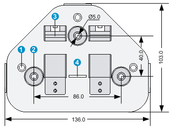
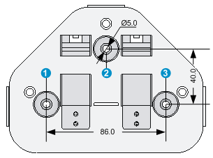
The three bolt holes shown in Figure 11 are needed for mounting the AP on a ceiling.
Figure 11 Bolt holes on the wall-mounting bracket (in mm)
|
(1) through (3) Bolt holes |
To install the AP on a ceiling:
1. Drill two 5.0 mm (0.20 in) diameter holes in the ceiling where you want to mount the AP. The distance between the two holes must be the same as the distance between the two bolt holes on the mounting bracket.
2. Insert the hex-head bolts into the bolt holes on the mounting bracket and the holes in the ceiling. From above the ceiling, fasten the hex nuts to the hex-head bolts to fix the mounting bracket to the ceiling.
3. Connect the AP to the network by using an Ethernet cable.
4. Install the AP to the wall-mounting bracket. For more information, see “Mounting the AP on a wall.”
Figure 12 Mount the mounting bracket to a ceiling
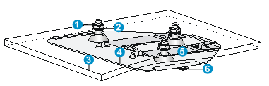
|
(1) Nut |
(2) Washer |
|
(3) Ceiling |
(4) Wall-mounting bracket |
|
(5) Hex-head bolt |
(6) Hook |
|
|
CAUTION: Check that the AP is secured to the mounting bracket to avoid falloff. |
Connecting the power supply
The WA2610i-GN can be powered through PoE or a power adaptor. You can select either method as needed.
Before connecting the power supply, check that the power supply is steady. You can use a local power source, uninterruptible power supply (UPS), or user-supplied power generator to supply power to the AP. Ensure easy connection, secure operation, and convenient check and repair of the AP.
The AC-input voltage range is 100 VAC to 240 VAC, 50 or 60 Hz.
|
|
CAUTION: · Use a voltage stabilizer when necessary. · If uninterrupted communication is required, use a UPS power supply. |
Check before power-on
Check the following items before you power on the AP:
· The power supply is well grounded when the AP adopts local power supply.
· The PoE power supply is well grounded when the AP adopts PoE power supply.
Local power supply
|
|
NOTE: No power adapter and power cable are shipped with the AP. |
Table 2 Power adapter specifications
|
Item |
Description |
|
Input |
100 VAC to 240 VAC |
|
Output |
+48V |
The WA2610i-GN supports both AC and DC power adapters. You can connect the power port of the AP to the power source through a power adapter to supply power to the AP.
Figure 13 Local power supply connection
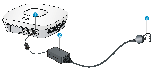
|
(1) Power port |
(2) Power adapter |
(3) Power source |
PoE power supply
|
|
CAUTION: · When you apply 802.3af PoE power supply, connect one end of the network cable to the network port on the AP, and the other end to an Ethernet port on a PoE-capable device (for example, a PoE-capable Ethernet switch). · Identify the marks for the network port and console port to avoid connection mistakes. |
If the uplink device of the AP is a PoE switch, use an Ethernet cable to directly connect the Ethernet interface of the AP to the PoE device.
Figure 14 PoE connection
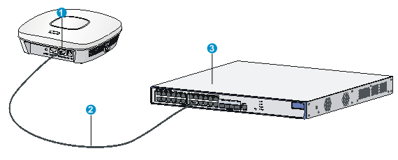
|
(1) Ethernet Port |
(2) Ethernet Cable |
(3) PoE switch |
Check after power-on
After powering on the AP, check the AP status LED. For more information about AP LEDs, see “Appendix LEDs and ports.”
Connecting the AP to the network
APs can access the Internet or metropolitan area network (MAN) through the Ethernet uplink interface. To implement Internet or MAN access, connect the Ethernet port of the AP to an Ethernet port of an Ethernet switch.
Checking the network connection for the fit AP
When the AP operates as a fit AP, all of its settings are configured on the AC. You can use the display wlan ap all command to check the AP status on the AC. When the AP status is R/M, the AP has been successfully connected to the AC.
<AC>display wlan ap all
Total Number of APs configured : 1
Total Number of configured APs connected : 1
Total Number of auto APs connected : 0
AP Profiles
State : I = Idle, J = Join, JA = JoinAck, IL = ImageLoad
C = Config, R = Run, KU = KeyUpdate, KC = KeyCfm
--------------------------------------------------------------------------------
AP Name State Model Serial-ID
--------------------------------------------------------------------------------
ap1 R/M WA2610i-GN 219801A0CLC118000435
--------------------------------------------------------------------------------
<AC>
Checking the network connection for the fat AP
When the AP operates as a fat AP, use the ping command to ping the uplink network. If the network can be pinged successfully, the AP is successfully connected to the network.
|
|
NOTE: The WA2610i-GN is usually installed on a high position. H3C recommends that you log in to the AP to configure related settings before you install the AP. |
When the WA2610i-GN operates as a fat AP, you can log in to the AP through the console port, or through Telnet or web to configure the AP, but you must obtain the IP address of the AP first.
· Logging in through the console port—Logging in through the console port is the most fundamental login method. To log in through other methods, you must log in through the console port and perform the required configurations.
· Logging in through Telnet—You can telnet to the device to remotely manage and maintain it.
· Logging in through web—You can log in to the web interface of the device to remotely manage and maintain it.
Logging in through the console port
Prepare the following before you log in through the console port:
· An 8-core shielded console cable, with a crimped RJ-45 connector at one end, and a DB-9 female connector at the other end.
· A configuration terminal—A laptop or PC with a serial port.
Setting up the configuration environment
|
|
NOTE: The serial ports on PCs do not support hot swapping. If the AP has been powered on, connect the console cable to the PC before connecting to the AP, and when you disconnect the cable, first disconnect from the AP. |
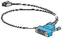
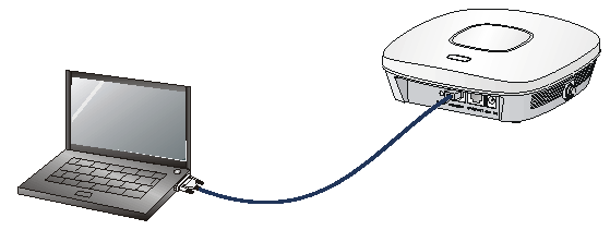
To connect the console cable:
1. Plug the DB-9 female connector to the serial port of the PC.
2. Connect the RJ-45 connector to the console port of the AP.
Figure 15 Connect the console cable
3. Power on the AP.
The AP’s startup information will be displayed.
Setting terminal parameters
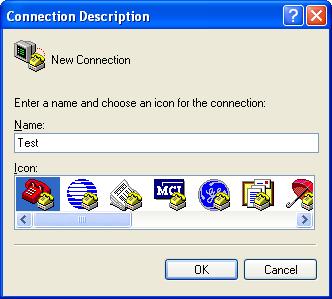
To set terminal parameters, for example, on a Windows XP HyperTerminal:
1. Select Start > All Programs > Accessories > Communications > HyperTerminal.
The Connection Description dialog box appears.
2. Enter the name of the new connection in the Name field and click OK.
Figure 16 Connection description
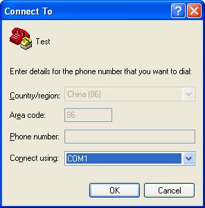
3. Select the serial port to be used from the Connect using list, and click OK.
Figure 17 Set the serial port used by the HyperTerminal connection
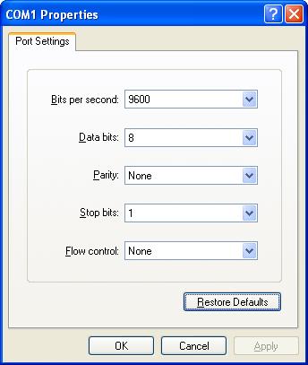
4. Set Bits per second to 9600, Data bits to 8, Parity to None, Stop bits to 1, and Flow control to None, and click OK.
Figure 18 Set the serial port parameters
|
|
NOTE: To restore the default settings, click Restore Defaults. |
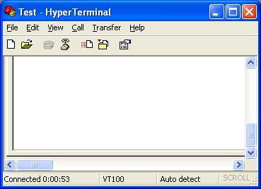
The HyperTerminal window appears.
Figure 19 HyperTerminal window
Logging in through the console port
Power on the AP, and you can see the following information:
System is starting...
Booting Normal Extend BootWare.
…
System application is starting...
Startup configuration file does not exist.
User interface con0 is available.
Press ENTER to get started.
Logging in through Telnet or web
By default, the Telnet and web functions are enabled. You can use the following default settings to log in to the web interface:
· Username—admin
· Password—h3capadmin
· Management IP address of VLAN-interface 1 of the AP—192.168.0.50, with the subnet mask 255.255.255.0.
If the default IP address is changed, contact the administrator to get the new IP address, or use the display vlan 1 command to view the IP address after logging in to the AP from the console port.
|
|
NOTE: For more information about Telnet or web login configuration, see H3C WA Series Access Points Configuration Guides. |
Appendix LEDs and ports
LEDs
Table 3 describes the LEDs provided by the WA2610i-GN.
|
Mark |
Color |
Status |
Description |
|
|
Green |
Flashing at 1 Hz |
The AP is booting. NOTE: When the AP operates as a fit AP, it is always in this state before it is registered to an AC. |
|
Breathing |
A client is connected to the 2.4G port. |
||
|
Blue |
Flashing at 0.25 Hz |
The AP has been booted, and is in standby state (no client is connected to the AP). NOTE: When the AP operates as a fit AP, this state indicates the AP has been registered to an AC. |
|
|
Flashing at 4 Hz |
The AP is updating its system software image (only available when the AP operates as a fit AP). |
||
|
Red |
Steady on |
An initialization exception has occurred to the AP. |
|
|
Flashing at 1 Hz |
The AP cannot detect any radio interface. |
||
|
Flashing at 8 Hz |
An Ethernet port or radio interface is operating abnormally. |
||
|
Alternating green and blue |
Alternating flashing at 1 Hz |
Blinking mode. NOTE: When the fit AP associated with the AC receives the blinking command sent by the AC, it flashes green and blue to show the fit AP has been associated with the AC. |
|
|
NOTE: For more information about the blinking mode, see WX Series Access Controllers Configuration Guides. |
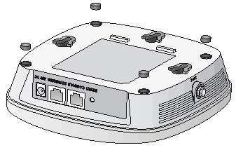
Ports
The WA2610i-GN provides the following external ports:
· Two 2.4 GHz antenna ports
· A console port
· A 10/100/1000 Mbps copper Ethernet port
· A power supply port
|
|
NOTE: The WA2610i-GN also provides a reset button. |
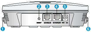
Figure 20 WA2610i-GN ports
|
(1) Ethernet Port |
(2) Ethernet Cable |
(3) PoE switch |
|
(4) 10/100/1000 Mbps copper Ethernet port |
(5) Local power port |
(6) 2.4G antenna port 1 |
Table 4 WA2610i-GN port description
|
Port |
Standards and protocols |
Description |
|
2.4G-1/2 |
· IEEE802.11b · IEEE802.11g · IEEE802.11n |
The antenna ports are provided for 2.4 GHz single-RF antennas |
|
48V DC |
· N/A |
The local power port is used for +48 VDC power supply to the device. |
|
ETHERNET |
· IEEE802.3 · IEEE802.3u · IEEE802.3af |
10/100/1000 Mbps copper Ethernet port .The Ethernet port can serve as an uplink interface to access the Internet or MAN, and as an 802.3af-compliant PoE port at the same time. |
|
Console port |
RS/EIA-232 |
The console port is used for configuration and management (for debugging when the AP operates as a fit AP). |
Check after power-on,12
Check before power-on,11
Checking the network connection for the fat AP,13
Checking the network connection for the fit AP,12
Local power supply,11
Logging in through the console port,17
Mounting the AP on a ceiling,9
Mounting the AP on a table,5
Mounting the AP on a wall,6
PoE power supply,12
Setting terminal parameters,15
Setting up the configuration environment,14