- Table of Contents
-
- 06-Layer 3 - IP Routing Configuration Guide
- 00-Preface
- 01-IP routing basics
- 02-Static routing configuration
- 03-RIP configuration
- 04-OSPF configuration
- 05-IS-IS configuration
- 06-BGP configuration
- 07-Policy-based routing configuration
- 08-IPv6 static routing configuration
- 09-RIPng configuration
- 10-OSPFv3 configuration
- 11-IPv6 IS-IS configuration
- 12-IPv6 policy-based routing configuration
- 13-Routing policy configuration
- Related Documents
-
| Title | Size | Download |
|---|---|---|
| 10-OSPFv3 configuration | 308.77 KB |
Contents
OSPFv3 configuration task list
Configuring OSPFv3 area parameters
Configuring an OSPFv3 virtual link
Configuring OSPFv3 network types
Configuring the OSPFv3 network type for an interface
Configuring an NBMA or P2MP neighbor
Configuring OSPFv3 route control
Configuring OSPFv3 route summarization
Configuring OSPFv3 inbound route filtering
Configuring Inter-Area-Prefix-LSA filtering
Configuring an OSPFv3 cost for an interface
Configuring the maximum number of OSPFv3 ECMP routes
Configuring a preference for OSPFv3
Configuring OSPFv3 route redistribution
Tuning and optimizing OSPFv3 networks
Specifying LSA transmission delay
Specifying SPF calculation interval
Specifying the LSA generation interval
Configuring a DR priority for an interface
Ignoring MTU check for DD packets
Disabling interfaces from receiving and sending OSPFv3 packets
Enabling the logging of neighbor state changes
Displaying and maintaining OSPFv3
Configuring OSPFv3 DR election
Configuring OSPFv3 route redistribution
This chapter describes how to configure RFC 5340-compliant Open Shortest Path First version 3 (OSPFv3) for an IPv6 network. For more information about OSPFv2, see "Configuring OSPF".
OSPFv3 overview
OSPFv3 and OSPFv2 have the following in common:
· 32-bit router ID and area ID
· Hello, Database Description (DD), Link State Request (LSR), Link State Update (LSU), Link State Acknowledgment (LSAck)
· Mechanisms for finding neighbors and establishing adjacencies
· Mechanisms for advertising and aging LSAs
OSPFv3 and OSPFv2 have the following differences:
· OSPFv3 runs on a per-link basis. OSPFv2 runs on a per-IP-subnet basis.
· OSPFv3 supports running multiple processes on an interface, but OSPFv2 does not support.
· OSPFv3 identifies neighbors by router ID. OSPFv2 identifies neighbors by IP address.
OSPFv3 packets
OSPFv3 uses the following packet types:
· Hello—Periodically sent to find and maintain neighbors, containing timer values, information about the DR, BDR, and known neighbors.
· DD—Describes the digest of each LSA in the LSDB, exchanged between two routers for data synchronization.
· LSR—Requests needed LSAs from the neighbor. After exchanging the DD packets, the two routers know which LSAs of the neighbor are missing from their LSDBs. They then send an LSR packet to each other, requesting the missing LSAs. The LSA packet contains the digest of the missing LSAs.
· LSU—Transmits the requested LSAs to the neighbor
· LSAck—Acknowledges received LSU packets.
OSPFv3 LSA types
OSPFv3 sends routing information in the following types of LSAs as defined in RFC 5340:
· Router-LSA—Originated by all routers. This LSA describes the collected states of the router's interfaces to an area, and is flooded throughout a single area only.
· Network-LSA—Originated for broadcast and NBMA networks by the DR. This LSA contains the list of routers connected to the network, and is flooded throughout a single area only.
· Inter-Area-Prefix-LSA—Originated by ABRs and flooded throughout the LSA's associated area. Each Inter-Area-Prefix-LSA describes a route with IPv6 address prefix to a destination outside the area, yet still inside the AS.
· Inter-Area-Router-LSA—Originated by ABRs and flooded throughout the LSA's associated area. Each Inter-Area-Router-LSA describes a route to ASBR.
· AS-external-LSA—Originated by ASBRs, and flooded throughout the AS, except stub and NSSA areas. Each AS-external-LSA describes a route to another AS. A default route can be described by an AS external LSA.
· Link-LSA—A router originates a separate Link-LSA for each attached link. Link-LSAs have link-local flooding scope. Each Link-LSA describes the IPv6 address prefix of the link and Link-local address of the router.
· Intra-Area-Prefix-LSA—Each Intra-Area-Prefix-LSA contains IPv6 prefix information on a router, stub area, or transit area information, and has area flooding scope. It was introduced because Router-LSAs and Network-LSAs contain no address information.
RFC 5187 defines the Grace-LSA. A Grace-LSA is generated by a GR (Graceful Restart) Restarter at reboot and transmitted on the local link. The restarter describes the cause and interval of the reboot in the Grace-LSA to tell its neighbors that it performs a GR operation.
Protocols and standards
· RFC 5340, OSPF for IPv6
· RFC 2328, OSPF Version 2
· RFC 5187, OSPFv3 Graceful Restart
OSPFv3 configuration task list
Enabling OSPFv3
Before you enable OSPFv3, configure IPv6 addresses for interfaces to ensure IPv6 connectivity between neighboring nodes.
To enable an OSPFv3 process on a router:
· Enable the OSPFv3 process globally.
· Assign the OSPFv3 process a router ID.
· Enable the OSPFv3 process on related interfaces.
The router ID uniquely identifies the router within an AS. If a router runs multiple OSPFv3 processes, you must specify a unique router ID for each process.
An OSPFv3 process ID has only local significance. Process 1 on a router can exchange packets with process 2 on another router.
To enable OSPFv3:
|
Step |
Command |
Remarks |
|
1. Enter system view. |
system-view |
N/A |
|
2. Enable an OSPFv3 process and enter its view. |
ospfv3 [ process-id | vpn-instance vpn-instance-name ] * |
By default, no OSPFv3 process is enabled. |
|
3. Specify a router ID. |
router-id router-id |
By default, no router ID is configured. |
|
4. Enter interface view. |
interface interface-type interface-number |
N/A |
|
5. Enable an OSPFv3 process on the interface. |
ospfv3 process-id area area-id [ instance instance-id ] |
No OSPFv3 process is enabled on an interface by default. |
Configuring OSPFv3 area parameters
OSPFv3 has the same stub area and virtual link features as OSPFv2.
After you split an OSPFv3 AS into multiple areas, the LSA number is reduced and OSPFv3 applications are extended. To further reduce the size of routing tables and the number of LSAs, configure the non-backbone areas at an AS edge as stub areas.
Non-backbone areas exchange routing information through the backbone area, so the backbone and non-backbone areas (including the backbone itself) must be fully meshed. If no connectivity can be achieved, configure virtual links.
Configuration prerequisites
Before you configure OSPFv3 area parameters, enable OSPFv3.
Configuring a stub area
All the routers attached to a stub area must be configured with the stub command. The keyword no-summary is only available on the ABR of the stub area.
If you use the stub command with the keyword no-summary on an ABR, the ABR advertises a default route in an Inter-Area-Prefix-LSA into the stub area. No AS-external-LSA, Inter-Area-Prefix-LSA, or other Inter-Area-Router-LSA is advertised in the area. The stub area of this kind is also known as a "totally stub area."
To configure an OSPFv3 stub area:
|
Step |
Command |
Remarks |
|
1. Enter system view. |
system-view |
N/A |
|
2. Enter OSPFv3 view. |
ospfv3 [ process-id | vpn-instance vpn-instance-name ] * |
N/A |
|
3. Enter OSPFv3 area view. |
area area-id |
N/A |
|
4. Configure the area as a stub area. |
stub [ default-route-advertise-always | no-summary ] * |
By default, no stub area is configured as a stub area. |
|
5. (Optional.) Specify a cost for the default route advertised to the stub area. |
default-cost value |
The default setting is 1. |
Configuring an OSPFv3 virtual link
You can configure a virtual link to maintain connectivity between a non-backbone area and the backbone, or in the backbone itself.
|
|
IMPORTANT: · Both ends of a virtual link are ABRs that must be configured with the vlink-peer command. · Do not configure virtual links in the areas of a GR-capable process. |
To configure a virtual link:
|
Step |
Command |
Remarks |
|
1. Enter system view. |
system-view |
N/A |
|
1. Enter OSPFv3 view. |
ospfv3 [ process-id | vpn-instance vpn-instance-name ] * |
N/A |
|
2. Enter OSPFv3 area view. |
area area-id |
N/A |
|
3. Configure a virtual link. |
vlink-peer router-id [ dead seconds | hello seconds | instance instance-id | retransmit seconds | trans-delay seconds ] * |
By default, no virtual link is configured. |
Configuring OSPFv3 network types
OSPFv3 classifies networks into the following types by the link layer protocol:
· Broadcast—When the link layer protocol is Ethernet or FDDI, OSPFv3 considers the network type as broadcast by default.
· NBMA—When the link layer protocol is ATM, Frame Relay, or X.25, OSPFv3 considers the network type as NBMA by default.
· P2P—When the link layer protocol is PPP, LAPB, HDLC, or POS, OSPFv3 considers the network type as P2P by default.
Follow these guidelines when you change the network type of an OSPFv3 interface:
· An NBMA network must be fully connected. Any two routers in the network must be directly reachable to each other through a virtual circuit. If no such direct link is available, you must change the network type through a command.
· If direct connections are not available between some routers in an NBMA network, the type of interfaces associated must be configured as P2MP, or as P2P for interfaces with only one neighbor.
Configuration prerequisites
Before you configure OSPFv3 network types, enable OSPFv3.
Configuring the OSPFv3 network type for an interface
|
Step |
Command |
Remarks |
|
1. Enter system view. |
system-view |
N/A |
|
2. Enter interface view. |
interface interface-type interface-number |
N/A |
|
3. Configure a network type for the OSPFv3 interface. |
ospfv3 network-type { broadcast | nbma | p2mp [ unicast ] | p2p } [ instance instance-id ] |
By default, the network type of an interface depends on the media type of the interface. |
Configuring an NBMA or P2MP neighbor
For NBMA and P2MP interfaces (only when in unicast mode), you must specify the link-local IP addresses of their neighbors because these interfaces cannot find neighbors through broadcasting hello packets. For NBMA interfaces, you can also specify DR priorities for neighbors.
To configure an NBMA or P2MP (unicast) neighbor and its DR priority:
|
Step |
Command |
Remarks |
|
1. Enter system view. |
system-view |
N/A |
|
2. Enter interface view. |
interface interface-type interface-number |
N/A |
|
3. Specify an NBMA or P2MP (unicast) neighbor and its DR priority. |
ospfv3 peer ipv6-address [ cost value | dr-priority dr-priority ] [ instance instance-id ] |
By default, no link-local address is specified for the neighbor interface. |
Configuring OSPFv3 route control
Configuration prerequisites
Before you configure OSPFv3 route control, complete the following tasks:
· Configure IPv6 addresses for interfaces to ensure IPv6 connectivity between neighboring nodes.
· Enable OSPFv3.
Configuring OSPFv3 route summarization
If contiguous network segments exist in an area, you can use the abr-summary command to summarize them into one network segment on the ABR. The ABR will advertise only the summary route. Any LSA falling into the specified network segment will not be advertised, reducing the LSDB size in other areas.
To configure route summarization:
|
Step |
Command |
Remarks |
|
1. Enter system view. |
system-view |
N/A |
|
2. Enter OSPFv3 view. |
ospfv3 [ process-id | vpn-instance vpn-instance-name ] * |
N/A |
|
3. Enter OSPFv3 area view. |
area area-id |
N/A |
|
4. Configure route summarization. |
abr-summary ipv6-address prefix-length [ not-advertise ] [ cost value ] |
By default, route summarization is not configured. The abr-summary command takes effect only on ABRs. |
Configuring OSPFv3 inbound route filtering
According to some rules, you can configure OSPFv3 to filter routes calculated using received LSAs.
To configure OSPFv3 to filter routes calculated using received LSAs:
|
Step |
Command |
Remarks |
|
1. Enter system view. |
system-view |
N/A |
|
2. Enter OSPFv3 view. |
ospfv3 [ process-id | vpn-instance vpn-instance-name ] * |
N/A |
|
3. Configure OSPFv3 to filter routes calculated using received LSAs. |
filter-policy { acl6-number [ gateway prefix-list-name ] | prefix-list prefix-list-name [ gateway prefix-list-name ] | gateway prefix-list-name | route-policy route-policy-name } import |
By default, OSPFv3 accepts all routes calculated using received LSAs. This command can only filter routes computed by OSPFv3. Only routes not filtered out can be added into the local routing table. |
Configuring Inter-Area-Prefix-LSA filtering
|
Step |
Command |
Remarks |
|
1. Enter system view. |
system-view |
N/A |
|
2. Enter OSPFv3 view. |
ospfv3 [ process-id | vpn-instance vpn-instance-name ] * |
N/A |
|
3. Enter OSPFv3 area view. |
area area-id |
N/A |
|
4. Configure OSPFv3 to filter Inter-Area-Prefix-LSAs. |
filter { acl6-number | prefix-list prefix-list-name | route-policy route-policy-name } { export | import } |
By default, OSPFv3 accepts all Inter-Area-Prefix-LSAs. This command takes effect only on ABRs. |
Configuring an OSPFv3 cost for an interface
You can configure an OSPFv3 cost for an interface with one of the following methods:
· Configure the cost value in interface view.
· Configure a bandwidth reference value for the interface, and OSPFv3 computes the cost automatically based on the bandwidth reference value: Interface OSPFv3 cost = Bandwidth reference value (100 Mbps)/Interface bandwidth (Mbps). If the calculated cost is greater than 65535, the value of 65535 is used; if the calculated cost is smaller than 1, the value of 1 is used.
If no cost is configured for an interface, OSPFv3 automatically computes the cost for the interface.
To configure an OSPFv3 cost for an interface:
|
Step |
Command |
Remarks |
|
1. Enter system view. |
system-view |
N/A |
|
2. Enter interface view. |
interface interface-type interface-number |
N/A |
|
3. Configure an OSPFv3 cost for the interface. |
ospfv3 cost value [ instance instance-id ] |
By default, the OSPF cost is 1 for a VLAN interface, is 0 for a loopback interface, and is automatically computed according to the interface bandwidth for other interfaces. |
To configure a bandwidth reference value:
|
Step |
Command |
Remarks |
|
1. Enter system view. |
system-view |
N/A |
|
2. Enter OSPFv3 view. |
ospfv3 [ process-id | vpn-instance vpn-instance-name ] * |
N/A |
|
3. Configure a bandwidth reference value. |
bandwidth-reference value |
The default setting is 100 Mbps. |
Configuring the maximum number of OSPFv3 ECMP routes
Perform this task to implement load sharing over ECMP routes.
To configure the maximum number of ECMP routes:
|
Step |
Command |
Remarks |
|
1. Enter system view. |
system-view |
N/A |
|
2. Enter OSPFv3 view. |
ospfv3 [ process-id | vpn-instance vpn-instance-name ] * |
N/A |
|
3. Specify the maximum number of ECMP routes. |
maximum load-balancing maximum |
By default, the maximum number of ECMP routes is 32. |
Configuring a preference for OSPFv3
A router can run multiple routing protocols. The system assigns a priority for each protocol. When these routing protocols find the same route, the route found by the protocol with the highest priority is selected.
To configure a preference for OSPFv3:
|
Step |
Command |
Remarks |
|
1. Enter system view. |
system-view |
N/A |
|
2. Enter OSPFv3 view. |
ospfv3 [ process-id | vpn-instance vpn-instance-name ] * |
N/A |
|
3. Configure a preference for OSPFv3. |
preference [ ase ] [ route-policy route-policy-name ] preference |
By default, the preference of OSPFv3 internal routes is 10, and the priority of OSPFv3 external routes is 150. |
Configuring OSPFv3 route redistribution
Because OSPFv3 is a link state routing protocol, it cannot directly filter LSAs to be advertised. OSPFv3 filters only redistributed routes. Only routes that are not filtered out can be advertised in LSAs.
Executing the import-route or default-route-advertise command on a router makes it become an ASBR.
To configure OSPFv3 route redistribution:
|
Step |
Command |
Remarks |
|
1. Enter system view. |
system-view |
N/A |
|
2. Enter OSPFv3 view. |
ospfv3 [ process-id | vpn-instance vpn-instance-name ] * |
N/A |
|
3. (Optional.) Specify a default cost for redistributed routes. |
default cost value |
The default setting is 1. |
|
4. Configure OSPFv3 to redistribute routes from other routing protocols. |
import-route protocol [ process-id | all-processes | allow-ibgp ] [ cost cost | route-policy route-policy-name | type type ] * |
By default, route redistribution is disabled. |
|
5. (Optional.) Configure OSPFv3 to redistribute a default route. |
default-route-advertise [ [ always | permit-calculate-other ] | cost cost | route-policy route-policy-name | type type ] * |
By default, no default route is redistributed. This command can only inject and advertise a default route. |
|
6. (Optional.) Configure OSPFv3 to filter redistributed routes. |
filter-policy { acl6-number | prefix-list prefix-list-name } export [ protocol [ process-id ] ] |
By default, OSPFv3 accepts all redistributed routes. This command filters only routes redistributed with the import-route command. If the import-route command is not configured, executing this command does not take effect. |
Tuning and optimizing OSPFv3 networks
This section describes configurations of OSPFv3 timers, interface DR priority, and the logging of neighbor state changes.
Configuration prerequisites
Before you tune and optimize OSPFv3 networks, complete the following tasks:
· Configure IPv6 addresses for interfaces to ensure IPv6 connectivity between neighboring nodes.
· Enable OSPFv3.
Configuring OSPFv3 timers
|
Command |
Remarks |
|
|
1. Enter system view. |
system-view |
N/A |
|
2. Enter interface view. |
interface interface-type interface-number |
N/A |
|
3. Configure the hello interval. |
ospfv3 timer hello seconds [ instance instance-id ] |
By default, the hello interval on P2P and broadcast interfaces is 10 seconds. |
|
4. Configure the dead interval. |
ospfv3 timer dead seconds [ instance instance-id ] |
By default, the dead interval on P2P and broadcast interfaces is 40 seconds. The dead interval set on neighboring interfaces cannot be too short. Otherwise, a neighbor is easily considered down. |
|
5. Configure the poll interval. |
ospfv3 timer poll seconds [ instance instance-id ] |
By default, the poll interval is 120 seconds. |
|
6. Configure the LSA retransmission interval. |
ospfv3 timer retransmit interval [ instance instance-id ] |
The default setting is 5 seconds. The LSA retransmission interval cannot be too short. Otherwise, unnecessary retransmissions will occur. |
Specifying LSA transmission delay
Each LSA in the LSDB has an age that is incremented by 1 every second, but the age does not change during transmission. Therefore, it is necessary to add a transmission delay into the age time, especially for low-speed links.
To specify the LSA transmission delay on an interface:
|
Step |
Command |
Remarks |
|
1. Enter system view. |
system-view |
N/A |
|
2. Enter interface view. |
interface interface-type interface-number |
N/A |
|
3. Specify the LSA transmission delay. |
ospf trans-delay seconds [ instance instance-id ] |
By default, the LSA transmission delay is 1 second. |
Specifying SPF calculation interval
LSDB changes result in SPF calculations. When the topology changes frequently, a large amount of network and router resources are occupied by SPF calculation. You can adjust the SPF calculation interval to reduce the impact.
When network changes are not frequent, the minimum-interval is adopted. If network changes become frequent, the SPF calculation interval is incremented by incremental-interval × 2n-2 (n is the number of generation times) each time an SPF calculation occurs until the maximum-interval is reached.
To configure SPF calculation interval:
|
Step |
Command |
Remarks |
|
1. Enter system view. |
system-view |
N/A |
|
2. Enter OSPFv3 view. |
ospfv3 [ process-id | vpn-instance vpn-instance-name ] * |
N/A |
|
3. Specify the SPF calculation interval. |
spf-schedule-interval maximum-interval [ minimum-interval [ incremental-interval ] ] |
By default: · The maximum interval is 5 seconds. · The minimum interval is 50 milliseconds. · The incremental interval is 200 milliseconds. |
Specifying the LSA generation interval
You can adjust the LSA generation interval to protect network resources and routers from being over consumed by frequent network changes.
When network changes are not frequent, LSAs are generated at the minimum-interval. If network changes become frequent, the LSA generation interval is incremented by incremental-interval × 2n-2 (n is the number of generation times) each time an LSA generation occurs until the maximum-interval is reached.
To configure the LSA generation interval:
|
Step |
Command |
Remarks |
|
1. Enter system view. |
system-view |
N/A |
|
2. Enter OSPFv3 view. |
ospf [ process-id | vpn-instance vpn-instance-name ] * |
N/A |
|
3. Configure the LSA generation interval. |
lsa-generation-interval maximum-interval [ minimum-interval [ incremental-interval ] ] |
By default, the maximum interval is 5 seconds, the minimum interval is 0 milliseconds, and the incremental interval is 0 milliseconds. |
Configuring a DR priority for an interface
The router priority is used for DR election. Interfaces having the priority 0 cannot become a DR or BDR.
To configure a DR priority for an interface:
|
Step |
Command |
Remarks |
|
1. Enter system view. |
system-view |
N/A |
|
2. Enter interface view. |
interface interface-type interface-number |
N/A |
|
3. Configure a router priority. |
ospfv3 dr-priority priority [ instance instance-id ] |
The default router priority is 1. |
Ignoring MTU check for DD packets
When LSAs are few in DD packets, it is unnecessary to check the MTU in DD packets to improve efficiency.
To ignore MTU check for DD packets:
|
Step |
Command |
Remarks |
|
1. Enter system view. |
system-view |
N/A |
|
2. Enter interface view. |
interface interface-type interface-number |
N/A |
|
3. Ignore MTU check for DD packets. |
ospfv3 mtu-ignore [ instance instance-id ] |
By default, OSPFv3 does not ignore MTU check for DD packets. |
Disabling interfaces from receiving and sending OSPFv3 packets
After an OSPF interface is set to silent, direct routes of the interface can still be advertised in Intra-Area-Prefix-LSAs through other interfaces, but other OSPFv3 packets cannot be advertised. No neighboring relationship can be established on the interface. This feature can enhance the adaptability of OSPFv3 networking.
To disable interfaces from receiving and sending OSPFv3 packets:
|
Step |
Command |
Remarks |
|
1. Enter system view. |
system-view |
N/A |
|
2. Enter OSPFv3 view. |
ospfv3 [ process-id | vpn-instance vpn-instance-name ] * |
N/A |
|
3. Disable interfaces from receiving and sending OSPFv3 packets. |
silent-interface { interface-type interface-number | all } |
By default, the interfaces are able to receive and send OSPFv3 packets. This command disables only the interfaces associated with the current process, though multiple OSPFv3 processes can disable the same interface from receiving and sending OSPFv3 packets. |
Enabling the logging of neighbor state changes
|
Step |
Command |
Remarks |
|
1. Enter system view. |
system-view |
N/A |
|
2. Enter OSPFv3 view. |
ospfv3 [ process-id | vpn-instance vpn-instance-name ] * |
N/A |
|
3. Enable the logging of neighbor state changes. |
log-peer-change |
By default, this feature is enabled. |
Configuring OSPFv3 GR
Graceful Restart ensures the continuity of packet forwarding when a routing protocol restarts or an active/standby switchover occurs:
· GR Restarter—Graceful restarting router. It must be Graceful Restart capable.
· GR Helper—The neighbor of the GR Restarter. It helps the GR Restarter to complete the GR process.
To prevent service interruption after a master/backup switchover, a GR Restarter running OSPFv3 must complete the following tasks:
· Keep the GR Restarter forwarding entries stable during reboot.
· Establish all adjacencies and obtain complete topology information after reboot.
After the active/standby switchover, the GR Restarter sends a Grace-LSA to tell its neighbors that it performs a GR. Upon receiving the Grace-LSA, the neighbors with the GR Helper capability enter the helper mode (and are called "GR Helpers"). Then, the GR Restarter retrieves its adjacencies and LSDB with the help of the GR Helpers.
Configuring GR Restarter
You can configure the GR Restarter capability on a GR Restarter.
To configure GR Restarter:
|
Step |
Command |
Remarks |
|
1. Enter system view. |
system-view |
N/A |
|
2. Enter OSPFv3 view. |
ospfv3 [ process-id | vpn-instance vpn-instance-name ] * |
N/A |
|
3. Enable the GR capability. |
graceful-restart enable |
By default, OSPFv3 GR Restarter capability is disabled. |
|
4. (Optional.) Configure the GR interval. |
graceful-restart interval interval-value |
By default, the GR interval is 120 seconds. |
Configuring GR Helper
You can configure the GR Helper capability on a GR Helper.
To configure GR Helper
|
Step |
Command |
Remarks |
|
1. Enter system view. |
system-view |
N/A |
|
2. Enter OSPFv3 view. |
ospfv3 [ process-id | vpn-instance vpn-instance-name ] * |
N/A |
|
3. Enable the GR Helper capability. |
graceful-restart helper enable |
By default, the GR Helper capability is enabled. |
|
4. Enable strict LSA checking. |
graceful-restart helper strict-lsa-checking |
By default, strict LSA checking is disabled. |
Configuring BFD for OSPFv3
After discovering neighbors by sending hello packets, OSPFv3 notifies BFD of the neighbor addresses, and BFD uses these addresses to establish sessions. Before a BFD session is established, it is in the down state. In this state, BFD control packets are sent at an interval of no less than 1 second to reduce BFD control packet traffic. After the BFD session is established, BFD control packets are sent at the negotiated interval, thereby implementing fast fault detection.
To configure BFD for OSPFv3, you need to configure OSPFv3 first.
To configure BFD for OSPFv3:
|
Step |
Command |
Remarks |
|
1. Enter system view. |
system-view |
N/A |
|
2. Enter OSPFv3 view. |
ospfv3 [ process-id | vpn-instance vpn-instance-name ] * |
N/A |
|
3. Specify a router ID. |
router-id router-id |
N/A |
|
4. Quit the OSPFv3 view. |
quit |
N/A |
|
5. Enter interface view. |
interface interface-type interface-number |
N/A |
|
6. Enable an OSPFv3 process on the interface. |
ospfv3 process-id area area-id [ instance instance-id ] |
N/A |
|
7. Enable BFD on the interface. |
ospfv3 bfd enable [ instance instance-id ] |
By default, BFD on the interface is disabled. |
Displaying and maintaining OSPFv3
Execute display commands in any view.
|
Purpose |
Command |
|
Display information about the routes to OSPFv3 ABR and ASBR. |
display ospfv3 [ process-id ] abr-asbr |
|
Display brief OSPFv3 process information. |
display ospfv3 [ process-id ] brief |
|
Display GR status of the specified OSPFv3 process. |
display ospfv3 [ process-id ] graceful-restart status |
|
Display OSPFv3 interface information. |
display ospfv3 [ process-id ] interface [ interface-type interface-number | verbose ] |
|
Display OSPFv3 LSDB information. |
display ospfv3 [ process-id ] lsdb [ { external | grace | inter-prefix | inter-router | intra-prefix | link | network | router | unknown [ type ] } [ link-state-id ] [ originate-router router-id | self-originate ] | statistics | total ] |
|
Display OSPFv3 neighbor information. |
display ospfv3 [ process-id ] [ area area-id ] peer [ [ interface-type interface-number ] [ verbose ] | peer-router-id | statistics ] |
|
Display OSPFv3 request list information. |
display ospfv3 [ process-id ] [ area area-id ] request-queue [ interface-type interface-number ] [ neighbor-id ] |
|
Display OSPFv3 retransmission list information. |
display ospfv3 [ process-id ] [ area area-id ] retrans-queue [ interface-type interface-number ] [ neighbor-id ] |
|
Display OSPFv3 routing information. |
display ospfv3 [ process-id ] routing [ ipv6-address prefix-length ] |
|
Display OSPFv3 statistics. |
display ospfv3 [ process-id ] statistics |
|
Display OSPFv3 virtual link information. |
display ospfv3 [ process-id ] vlink |
OSPFv3 configuration examples
By default, Ethernet, VLAN, and aggregate interfaces are down. To configure such an interface, bring the interface up by executing the undo shutdown command.
Configuring OSPFv3 areas
Network requirements
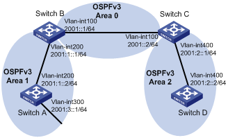
As shown in Figure 1:
· Enable OSPFv3 on all switches.
· Split the AS into three areas.
· Configure Switch B and Switch C as ABRs to forward routing information between areas.
· Configure Area 2 as a stub area to reduce LSAs in the area without affecting route reachability.
Configuration procedure
1. Configure IPv6 addresses for interfaces. (Details not shown.)
2. Configure basic OSPFv3:
# Configure Switch A: enable OSPFv3 and specify the router ID as 1.1.1.1.
<SwitchA> system-view
[SwitchA] ospfv3
[SwitchA-ospfv3-1] router-id 1.1.1.1
[SwitchA-ospfv3-1] quit
[SwitchA] interface vlan-interface 300
[SwitchA-Vlan-interface300] ospfv3 1 area 1
[SwitchA-Vlan-interface300] quit
[SwitchA] interface vlan-interface 200
[SwitchA-Vlan-interface200] ospfv3 1 area 1
[SwitchA-Vlan-interface200] quit
# Configure Switch B: enable OSPFv3 and specify the router ID as 2.2.2.2.
<SwitchB> system-view
[SwitchB] ospfv3
[SwitchB-ospf-1] router-id 2.2.2.2
[SwitchB-ospf-1] quit
[SwitchB] interface vlan-interface 100
[SwitchB-Vlan-interface100] ospfv3 1 area 0
[SwitchB-Vlan-interface100] quit
[SwitchB] interface vlan-interface 200
[SwitchB-Vlan-interface200] ospfv3 1 area 1
[SwitchB-Vlan-interface200] quit
# Configure Switch C: enable OSPFv3 and specify the router ID as 3.3.3.3.
<SwitchC> system-view
[SwitchC] ospfv3
[SwitchC-ospfv3-1] router-id 3.3.3.3
[SwitchC-ospfv3-1] quit
[SwitchC] interface vlan-interface 100
[SwitchC-Vlan-interface100] ospfv3 1 area 0
[SwitchC-Vlan-interface100] quit
[SwitchC] interface vlan-interface 400
[SwitchC-Vlan-interface400] ospfv3 1 area 2
[SwitchC-Vlan-interface400] quit
# Configure Switch D: enable OSPFv3 and specify the router ID as 4.4.4.4.
<SwitchD> system-view
[SwitchD] ospfv3
[SwitchD-ospfv3-1] router-id 4.4.4.4
[SwitchD-ospfv3-1] quit
[SwitchD] interface vlan-interface 400
[SwitchD-Vlan-interface400] ospfv3 1 area 2
[SwitchD-Vlan-interface400] quit
# Display OSPFv3 neighbors on Switch B.
[SwitchB] display ospfv3 peer
OSPFv3 Process 1 with Router ID 2.2.2.2
Area: 0.0.0.0
-------------------------------------------------------------------------
Router ID Pri State Dead-Time Interface Inst ID
3.3.3.3 1 Full/Backup 00:00:40 Vlan100 0
Area: 0.0.0.1
-------------------------------------------------------------------------
Router ID Pri State Dead-Time Interface Inst ID
1.1.1.1 1 Full/DR 00:00:40 Vlan200 0
# Display OSPFv3 neighbors on Switch C.
[SwitchC] display ospfv3 peer
OSPFv3 Process 1 with Router ID 3.3.3.3
Area: 0.0.0.0
-------------------------------------------------------------------------
Router ID Pri State Dead-Time Interface Inst ID
2.2.2.2 1 Full/DR 00:00:40 Vlan100 0
Area: 0.0.0.2
-------------------------------------------------------------------------
Router ID Pri State Dead-Time Interface Inst ID
4.4.4.4 1 Full/Backup 00:00:40 Vlan400 0
# Display OSPFv3 routing table information on Switch D.
[SwitchD] display ospfv3 routing
OSPFv3 Process 1 with Router ID 4.4.4.4
-------------------------------------------------------------------------
E1 - Type 1 external route, IA - Inter area route, I - Intra area route
E2 - Type 2 external route, * - Selected route
*Destination: 2001::/64
Type : IA Cost : 2
NextHop : FE80::F40D:0:93D0:1 Interface: Vlan400
*Destination: 2001:1::/64
Type : IA Cost : 3
NextHop : FE80::F40D:0:93D0:1 Interface: Vlan400
*Destination: 2001:2::/64
Type : I Cost : 1
NextHop : directly-connected Interface: Vlan400
*Destination: 2001:3::/64
Type : IA Cost : 4
NextHop : FE80::F40D:0:93D0:1 Interface: Vlan400
Total: 4
Intra area: 1 Inter area: 3 ASE: 0
3. Configure Area 2 as a stub area:
# Configure Switch D
[SwitchD] ospfv3
[SwitchD-ospfv3-1] area 2
[SwitchD-ospfv3-1-area-0.0.0.2] stub
# Configure Switch C, and specify the cost of the default route sent to the stub area as 10.
[SwitchC] ospfv3
[SwitchC-ospfv3-1] area 2
[SwitchC-ospfv3-1-area-0.0.0.2] stub
[SwitchC-ospfv3-1-area-0.0.0.2] default-cost 10
# Display OSPFv3 routing table information on Switch D.
[SwitchD] display ospfv3 routing
OSPFv3 Process 1 with Router ID 4.4.4.4
-------------------------------------------------------------------------
E1 - Type 1 external route, IA - Inter area route, I - Intra area route
E2 - Type 2 external route, * - Selected route
*Destination: ::/0
Type : IA Cost : 11
NextHop : FE80::F40D:0:93D0:1 Interface: Vlan400
*Destination: 2001::/64
Type : IA Cost : 2
NextHop : FE80::F40D:0:93D0:1 Interface: Vlan400
*Destination: 2001:1::/64
Type : IA Cost : 3
NextHop : FE80::F40D:0:93D0:1 Interface: Vlan400
*Destination: 2001:2::/64
Type : I Cost : 1
NextHop : directly-connected Interface: Vlan400
*Destination: 2001:3::/64
Type : IA Cost : 4
NextHop : FE80::F40D:0:93D0:1 Interface: Vlan400
Total: 5
Intra area: 1 Inter area: 4 ASE: 0
The output shows that a default route is added, and its cost is the cost of a direct route plus the configured cost.
4. Configure Area 2 as a totally stub area:
# Configure Area 2 as a totally stub area on Switch C.
[SwitchC-ospfv3-1-area-0.0.0.2] stub no-summary
# Display OSPFv3 routing table information on Switch D.
[SwitchD] display ospfv3 routing
OSPFv3 Process 1 with Router ID 4.4.4.4
-------------------------------------------------------------------------
E1 - Type 1 external route, IA - Inter area route, I - Intra area route
E2 - Type 2 external route, * - Selected route
*Destination: ::/0
Type : IA Cost : 11
NextHop : FE80::F40D:0:93D0:1 Interface: Vlan400
*Destination: 2001:2::/64
Type : I Cost : 1
NextHop : directly-connected Interface: Vlan400
Total: 2
Intra area: 1 Inter area: 1 ASE: 0
The output shows that route entries are reduced. All indirect routes are removed, except the default route.
Configuring OSPFv3 DR election
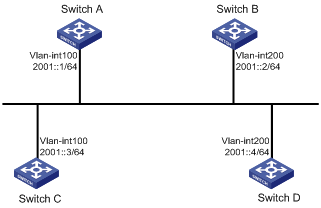
Network requirements
· Configure router priority 100 for Switch A, the highest priority on the network, so it will become the DR.
· Configure router priority 2 for Switch C, the second highest priority on the network, so it will become the BDR.
· Configure router priority 0 for Switch B, so it cannot become a DR or BDR.
· Switch D uses the default router priority 1.
Configuration procedure
1. Configure IPv6 addresses for interfaces. (Details not shown.)
2. Configure basic OSPFv3:
# Configure Switch A: enable OSPFv3 and specify the router ID as 1.1.1.1.
<SwitchA> system-view
[SwitchA] ospfv3
[SwitchA-ospfv3-1] router-id 1.1.1.1
[SwitchA-ospfv3-1] quit
[SwitchA] interface vlan-interface 100
[SwitchA-Vlan-interface100] ospfv3 1 area 0
[SwitchA-Vlan-interface100] quit
# Configure Switch B: enable OSPFv3 and specify the router ID as 2.2.2.2.
<SwitchB> system-view
[SwitchB] ospfv3
[SwitchB-ospfv3-1] router-id 2.2.2.2
[SwitchB-ospfv3-1] quit
[SwitchB] interface vlan-interface 200
[SwitchB-Vlan-interface200] ospfv3 1 area 0
[SwitchB-Vlan-interface200] quit
# Configure Switch C: enable OSPFv3 and specify the router ID as 3.3.3.3.
<SwitchC> system-view
[SwitchC] ospfv3
[SwitchC-ospfv3-1] router-id 3.3.3.3
[SwitchC-ospfv3-1] quit
[SwitchC] interface vlan-interface 100
[SwitchC-Vlan-interface100] ospfv3 1 area 0
[SwitchC-Vlan-interface100] quit
# Configure Switch D: enable OSPFv3 and specify the router ID as 4.4.4.4.
<SwitchD> system-view
[SwitchD] ospfv3
[SwitchD-ospfv3-1] router-id 4.4.4.4
[SwitchD-ospfv3-1] quit
[SwitchD] interface vlan-interface 200
[SwitchD-Vlan-interface200] ospfv3 1 area 0
[SwitchD-Vlan-interface200] quit
# Display neighbor information on Switch A. The switches have the same default DR priority 1, so Switch D (the switch with the highest Router ID) is elected as the DR, and Switch C is the BDR.
[SwitchA] display ospfv3 peer
OSPFv3 Process 1 with Router ID 1.1.1.1
Area: 0.0.0.0
-------------------------------------------------------------------------
Router ID Pri State Dead-Time Interface Inst ID
2.2.2.2 1 2-Way/DROther 00:00:36 Vlan200 0
3.3.3.3 1 Full/Backup 00:00:35 Vlan100 0
4.4.4.4 1 Full/DR 00:00:33 Vlan200 0
# Display neighbor information on Switch D. The neighbor states are all full.
[SwitchD] display ospfv3 peer
OSPFv3 Process 1 with Router ID 4.4.4.4
Area: 0.0.0.0
-------------------------------------------------------------------------
Router ID Pri State Dead-Time Interface Inst ID
1.1.1.1 1 Full/DROther 00:00:30 Vlan100 0
2.2.2.2 1 Full/DROther 00:00:37 Vlan200 0
3.3.3.3 1 Full/Backup 00:00:31 Vlan100 0
3. Configure router priorities for interfaces:
# Configure the router priority of VLAN-interface 100 as 100 on Switch A.
[SwitchA] interface Vlan-interface 100
[SwitchA-Vlan-interface100] ospfv3 dr-priority 100
[SwitchA-Vlan-interface100] quit
# Configure the router priority of VLAN-interface 200 as 0 on Switch B.
[SwitchB] interface vlan-interface 200
[SwitchB-Vlan-interface200] ospfv3 dr-priority 0
[SwitchB-Vlan-interface200] quit
# Configure the router priority of VLAN-interface 100 of Switch C as 2.
[SwitchC] interface Vlan-interface 100
[SwitchC-Vlan-interface100] ospfv3 dr-priority 2
[SwitchC-Vlan-interface100] quit
# Display neighbor information on Switch A. Router priorities have been updated, but the DR and BDR are not changed.
[SwitchA] display ospfv3 peer
OSPFv3 Process 1 with Router ID 1.1.1.1
Area: 0.0.0.0
-------------------------------------------------------------------------
Router ID Pri State Dead-Time Interface Inst ID
2.2.2.2 0 2-Way/DROther 00:00:36 Vlan200 0
3.3.3.3 2 Full/Backup 00:00:35 Vlan200 0
4.4.4.4 1 Full/DR 00:00:33 Vlan200 0
# Display neighbor information on Switch D. Switch D is still the DR.
[SwitchD] display ospfv3 peer
OSPFv3 Process 1 with Router ID 4.4.4.4
Area: 0.0.0.0
-------------------------------------------------------------------------
Router ID Pri State Dead-Time Interface Inst ID
1.1.1.1 100 Full/DROther 00:00:30 Vlan100 0
2.2.2.2 0 Full/DROther 00:00:37 Vlan200 0
3.3.3.3 2 Full/Backup 00:00:31 Vlan100 0
4. Restart DR and BDR election:
# Use the shutdown and undo shutdown commands on interfaces to restart DR and BDR election. (Details not shown.)
# Display neighbor information on Switch A. The output shows that Switch C becomes the BDR.
[SwitchA] display ospfv3 peer
OSPFv3 Process 1 with Router ID 1.1.1.1
Area: 0.0.0.0
-------------------------------------------------------------------------
Router ID Pri State Dead-Time Interface Inst ID
2.2.2.2 0 Full/DROther 00:00:36 Vlan200 0
3.3.3.3 2 Full/Backup 00:00:35 Vlan100 0
4.4.4.4 1 Full/DROther 00:00:33 Vlan200 0
# Display neighbor information on Switch D.
[SwitchD] display ospfv3 peer
OSPFv3 Process 1 with Router ID 4.4.4.4
Area: 0.0.0.0
-------------------------------------------------------------------------
Router ID Pri State Dead-Time Interface Inst ID
1.1.1.1 100 Full/DR 00:00:30 Vlan100 0
2.2.2.2 0 2-Way/DROther 00:00:37 Vlan200 0
3.3.3.3 2 Full/Backup 00:00:31 Vlan100 0
The output shows that Switch A becomes the DR.
Configuring OSPFv3 route redistribution
Network requirements
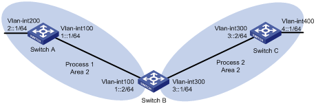
As shown in Figure 3:
· Switch A, Switch B, and Switch C are in Area 2.
· OSPFv3 process 1 and OSPFv3 process 2 run on Switch B. Switch B communicates with Switch A and Switch C through OSPFv3 process 1 and OSPFv3 process 2.
· Configure OSPFv3 process 2 to redistribute direct routes and the routes from OSPFv3 process 1 on Switch B, and set the default metric for redistributed routes to 3. Switch C can then learn the routes destined for 1::0/64 and 2::0/64, and Switch A cannot learn the routes destined for 3::0/64 or 4::0/64.
Configuration procedure
1. Configure IPv6 addresses for interfaces. (Details not shown.)
2. Configure basic OSPFv3:
# Enable OSPFv3 process 1 on Switch A.
<SwitchA> system-view
[SwitchA] ospfv3 1
[SwitchA-ospfv3-1] router-id 1.1.1.1
[SwitchA-ospfv3-1] quit
[SwitchA] interface vlan-interface 100
[SwitchA-Vlan-interface100] ospfv3 1 area 2
[SwitchA-Vlan-interface100] quit
[SwitchA] interface vlan-interface 200
[SwitchA-Vlan-interface200] ospfv3 1 area 2
[SwitchA-Vlan-interface200] quit
# Enable OSPFv3 process 1 and OSPFv3 process 2 on Switch B.
<SwitchB> system-view
[SwitchB] ospfv3 1
[SwitchB-ospfv3-1] router-id 2.2.2.2
[SwitchB-ospfv3-1] quit
[SwitchB] interface vlan-interface 100
[SwitchB-Vlan-interface100] ospfv3 1 area 2
[SwitchB-Vlan-interface100] quit
[SwitchB] ospfv3 2
[SwitchB-ospfv3-2] router-id 3.3.3.3
[SwitchB-ospfv3-2] quit
[SwitchB] interface vlan-interface 300
[SwitchB-Vlan-interface300] ospfv3 2 area 2
[SwitchB-Vlan-interface300] quit
# Enable OSPFv3 process 2 on Switch C.
<SwitchC> system-view
[SwitchC] ospfv3 2
[SwitchC-ospfv3-2] router-id 4.4.4.4
[SwitchC-ospfv3-2] quit
[SwitchC] interface vlan-interface 300
[SwitchC-Vlan-interface300] ospfv3 2 area 2
[SwitchC-Vlan-interface300] quit
[SwitchC] interface vlan-interface 400
[SwitchC-Vlan-interface400] ospfv3 2 area 2
[SwitchC-Vlan-interface400] quit
# Display the routing table on Switch C.
[SwitchC] display ipv6 routing-table
Destinations : 7 Routes : 7
Destination: ::1/128 Protocol : Direct
NextHop : ::1 Preference: 0
Interface : InLoop0 Cost : 0
Destination: 3::/64 Protocol : Direct
NextHop : 3::2 Preference: 0
Interface : Vlan300 Cost : 0
Destination: 3::2/128 Protocol : Direct
NextHop : ::1 Preference: 0
Interface : InLoop0 Cost : 0
Destination: 4::/64 Protocol : Direct
NextHop : 4::1 Preference: 0
Interface : Vlan400 Cost : 0
Destination: 4::1/128 Protocol : Direct
NextHop : ::1 Preference: 0
Interface : InLoop0 Cost : 0
Destination: FE80::/10 Protocol : Direct
NextHop : :: Preference: 0
Interface : NULL0 Cost : 0
Destination: FF00::/8 Protocol : Direct
NextHop : :: Preference: 0
Interface : NULL0
3. Configure OSPFv3 route redistribution:
# Configure OSPFv3 process 2 to redistribute direct routes and the routes from OSPFv3 process 1 on Switch B.
[SwitchB] ospfv3 2
[SwitchB-ospfv3-2] default cost 3
[SwitchB-ospfv3-2] import-route ospfv3 1
[SwitchB-ospfv3-2] import-route direct
[SwitchB-ospfv3-2] quit
# Display the routing table on Switch C.
[SwitchC] display ipv6 routing-table
Destinations : 9 Routes : 9
Destination: ::1/128 Protocol : Direct
NextHop : ::1 Preference: 0
Interface : InLoop0 Cost : 0
Destination: 1::/64 Protocol : OSPFv3
NextHop : FE80::200:CFF:FE01:1C03 Preference: 150
Interface : Vlan300 Cost : 3
Destination: 2::/64 Protocol : OSPFv3
NextHop : FE80::200:CFF:FE01:1C03 Preference: 150
Interface : Vlan300 Cost : 3
Destination: 3::/64 Protocol : Direct
NextHop : 3::2 Preference: 0
Interface : Vlan300 Cost : 0
Destination: 3::2/128 Protocol : Direct
NextHop : ::1 Preference: 0
Interface : InLoop0 Cost : 0
Destination: 4::/64 Protocol : Direct
NextHop : 4::1 Preference: 0
Interface : Vlan400 Cost : 0
Destination: 4::1/128 Protocol : Direct
NextHop : ::1 Preference: 0
Interface : InLoop0 Cost : 0
Destination: FE80::/10 Protocol : Direct
NextHop : :: Preference: 0
Interface : NULL0 Cost : 0
Destination: FF00::/8 Protocol : Direct
NextHop : :: Preference: 0
Interface : NULL0
Configuring OSPFv3 GR
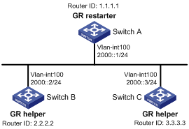
Network requirements
· As shown in Figure 4, Switch A, Switch B, and Switch C that reside in the same AS and the same OSPFv3 routing domain are GR capable.
· Switch A acts as the GR Restarter. Switch B and Switch C act as the GR Helpers, and synchronize their LSDBs with Switch A through out-of-band (OOB) communication of GR.
Configuration procedure
1. Configure IPv6 addresses for interfaces. (Details not shown.)
2. Configure basic OSPFv3:
# On Switch A, enable OSPFv3 process 1, enable GR, and set the router ID to 1.1.1.1.
<SwitchA> system-view
[SwitchA] ospfv3 1
[SwitchA-ospfv3-1] router-id 1.1.1.1
[SwitchA-ospfv3-1] graceful-restart enable
[SwitchA-ospfv3-1] quit
[SwitchA] interface vlan-interface 100
[SwitchA-Vlan-interface100] ospfv3 1 area 1
[SwitchA-Vlan-interface100] quit
# On Switch B, enable OSPFv3 and set the router ID to 2.2.2.2. (By default, GR helper is enabled on Switch B.)
<SwitchB> system-view
[SwitchB] ospfv3 1
[SwitchB-ospfv3-1] router-id 2.2.2.2
[SwitchB-ospfv3-1] quit
[SwitchB] interface vlan-interface 100
[SwitchB-Vlan-interface100] ospfv3 1 area 1
[SwitchB-Vlan-interface100] quit
# On Switch C, enable OSPFv3 and set the router ID to 3.3.3.3. (By default, GR helper is enabled on Switch C.)
<SwitchC> system-view
[SwitchC] ospfv3 1
[SwitchC-ospfv3-1] router-id 3.3.3.3
[SwitchC-ospfv3-1] quit
[SwitchC] interface vlan-interface 100
[SwitchC-Vlan-interface100] ospfv3 1 area 1
[SwitchC-Vlan-interface100] quit
Verifying the configuration
After all switches function properly, perform a master/backup switchover on Switch A to trigger an OSPFv3 GR operation.
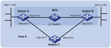
Configuring BFD for OSPFv3
Network requirements
As shown in Figure 5:
· Configure OSPFv3 on Switch A, Switch B and Switch C and configure BFD over the link Switch A<—>L2 Switch<—>Switch B.
· After the link Switch A<—>L2 Switch<—>Switch B fails, BFD can quickly detect the failure and notify OSPFv3 of the failure. Then Switch A and Switch B communicate through Switch C.
|
Device |
Interface |
IPv6 address |
Device |
Interface |
IPv6 address |
|
Switch A |
Vlan-int10 |
2001::1/64 |
Switch B |
Vlan-int10 |
2001::2/64 |
|
|
Vlan-int11 |
2001:2::1/64 |
|
Vlan-int13 |
2001:3::2/64 |
|
Switch C |
Vlan-int11 |
2001:2::2/64 |
|
|
|
|
|
Vlan-int13 |
2001:3::1/64 |
|
|
|
Configuration procedure
1. Configure IP addresses for the interfaces. (Details not shown.)
2. Configure basic OSPF:
# On Switch A, enable OSPFv3 and specify the router ID as 1.1.1.1.
<SwitchA> system-view
[SwitchA] ospfv3
[SwitchA-ospfv3-1] router-id 1.1.1.1
[SwitchA-ospfv3-1] quit
[SwitchA] interface vlan-interface 10
[SwitchA-Vlan-interface10] ospfv3 1 area 0
[SwitchA-Vlan-interface10] quit
[SwitchA] interface vlan-interface 11
[SwitchA-Vlan-interface11] ospfv3 1 area 0
[SwitchA-Vlan-interface11] quit
# On Switch B, enable OSPFv3 and specify the router ID as 2.2.2.2.
<SwitchB> system-view
[SwitchB] ospfv3
[SwitchB-ospf-1] router-id 2.2.2.2
[SwitchB-ospf-1] quit
[SwitchB] interface vlan-interface 10
[SwitchB-Vlan-interface10] ospfv3 1 area 0
[SwitchB-Vlan-interface10] quit
[SwitchB] interface vlan-interface 13
[SwitchB-Vlan-interface13] ospfv3 1 area 0
[SwitchB-Vlan-interface13] quit
# On Switch C, enable OSPFv3 and configure the router ID as 3.3.3.3.
<SwitchC> system-view
[SwitchC] ospfv3
[SwitchC-ospfv3-1] router-id 3.3.3.3
[SwitchC-ospfv3-1] quit
[SwitchC] interface vlan-interface 11
[SwitchC-Vlan-interface11] ospfv3 1 area 0
[SwitchC-Vlan-interface11] quit
[SwitchC] interface vlan-interface 13
[SwitchC-Vlan-interface13] ospfv3 1 area 0
[SwitchC-Vlan-interface13] quit
3. Configure BFD:
# Enable BFD and configure BFD parameters on Switch A.
[SwitchA] bfd session init-mode active
[SwitchA] interface vlan-interface 10
[SwitchA-Vlan-interface10] ospfv3 bfd enable
[SwitchA-Vlan-interface10] bfd min-transmit-interval 500
[SwitchA-Vlan-interface10] bfd min-receive-interval 500
[SwitchA-Vlan-interface10] bfd detect-multiplier 7
[SwitchA-Vlan-interface10] return
# Enable BFD and configure BFD parameters on Switch B.
[SwitchB] bfd session init-mode active
[SwitchB] interface vlan-interface 10
[SwitchB-Vlan-interface10] ospfv3 bfd enable
[SwitchB-Vlan-interface10] bfd min-transmit-interval 500
[SwitchB-Vlan-interface10] bfd min-receive-interval 500
[SwitchB-Vlan-interface10] bfd detect-multiplier 6
Verifying the configuration
# Display the BFD information of Switch A.
<SwitchA> display bfd session
Total Session Num: 1 Init Mode: Active
IPv6 Session Working Under Ctrl Mode:
Local Discr: 1441 Remote Discr: 1450
Source IP: FE80::20F:FF:FE00:1202 (link-local address of VLAN-interface 10 on Switch A)
Destination IP: FE80::20F:FF:FE00:1200 (link-local address of VLAN-interface 10 on Switch B)
Session State: Up Interface: Vlan10
Hold Time: 2319ms
# Display routes destined for 2001:4::0/64 on Switch A.
<SwitchA> display ipv6 routing-table 2001:4::0 64
Summary Count : 1
Destination: 2001:4::/64 Protocol : OSPFv3
NextHop : FE80::20F:FF:FE00:1200 Preference: 10
Interface : Vlan10 Cost : 1
The output information shows that Switch A communicates with Switch B through VLAN-interface 10. Then the link over VLAN-interface 10 fails.
# Display routes to 2001:4::0/64 on Switch A.
<SwitchA> display ipv6 routing-table 2001:4::0 64
Summary Count : 1
Destination: 2001:4::/64 Protocol : OSPFv3
NextHop : FE80::BAAF:67FF:FE27:DCD0 Preference: 10
Interface : Vlan11 Cost : 2
The output shows that Switch A communicates with Switch B through VLAN-interface 11.