- Table of Contents
-
- 04-Layer 2 - LAN Switching Configuration Guide
- 00-Preface
- 01-MAC address table configuration
- 02-Ethernet link aggregation configuration
- 03-Port isolation configuration
- 04-Spanning tree configuration
- 05-Loop detection configuration
- 06-VLAN configuration
- 07-QinQ configuration
- 08-VLAN mapping configuration
- 09-LLDP configuration
- Related Documents
-
| Title | Size | Download |
|---|---|---|
| 08-VLAN mapping configuration | 172.38 KB |
Contents
Application scenario of one-to-two VLAN mapping
One-to-two VLAN mapping implementation
Configuring one-to-two VLAN mapping
Configuring the customer-side port
Configuring the network-side port
Displaying and maintaining VLAN mapping
One-to-two VLAN mapping configuration example
Overview
VLAN mapping, also known as "VLAN translation," re-marks VLAN tagged packets with new VLAN IDs and enables translation between CVLANs and SVLANs. H3C provides one-to-two VLAN mapping, which tags single-tagged packets with an outer VLAN tag.
Application scenario of one-to-two VLAN mapping
Figure 1 shows a typical application scenario of one-to-two VLAN mapping. In the application scenario, remote sites of VPN A, Site 1 and Site 2, must communicate across the SP network. Site 1 and Site 2 are both in VLAN 5. The SP network assigns VLAN 100 to VPN A.
Figure 1 Application scenario of one-to-two VLAN mapping
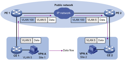
To enable the users of Site 1 to communicate with users of Site 2, PE2 removes the outer VLAN tag of the packet and forwards the packet to Site 2 through VLAN 5.
A packet from Site 2 to Site 1 is handled in a similar way.
You can use QinQ to implement one-to-two VLAN mapping. For information about how to implement one-to-two VLAN mapping through QinQ, see "Configuring QinQ."
Concepts and terms
Figure 2 shows a simplified network to help explain the concepts and terms that you may encounter when working with VLAN mapping:
Figure 2 Basic concepts of VLAN mapping
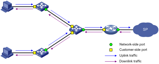
· Uplink traffic—Traffic transmitted from the customer network to the service provider network.
· Downlink traffic—Traffic transmitted from the service provider network to the customer network.
· Network-side port—A port connected to or closer to the service provider network.
· Customer-side port—A port connected to or closer to the customer network.
· Uplink policy—A QoS policy that defines VLAN mapping rules for uplink traffic.
· Downlink policy—A QoS policy that defines VLAN mapping rules for downlink traffic.
· Customer VLANs—CVLANs are VLANs assigned to customers.
· Service provider VLANs—SVLANs are VLANs assigned for transmitting traffic across the service provider network.
For more information about QoS policies, see ACL and QoS Configuration Guide.
One-to-two VLAN mapping implementation
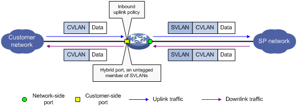
Implement one-to-two VLAN mapping through the following configurations, as shown in Figure 3:
· Apply an uplink policy to the incoming traffic on the customer-side port to tag the incoming packets from a certain CVLAN with an SVLAN tag. For more information about QoS policies, see ACL and QoS Configuration Guide.
· Configure the customer-side port as a hybrid port, and assign the port to SVLANs as an untagged member. When the port forwards the packets from these SVLANs, it removes their SVLAN tags.
Figure 3 One-to-two VLAN mapping implementation
Configuring one-to-two VLAN mapping
Perform these tasks to configure one-to-two VLAN mapping:
|
Tasks at a glance |
Configuring an uplink policy
You can configure an uplink policy to add an SVLAN tag to CVLAN-tagged packets.
To configure an uplink policy:
|
Step |
Command |
Remarks |
|
1. Enter system view. |
system-view |
N/A |
|
2. Configure a class for a CVLAN. |
a. Create a class and enter class view: b. Configure CVLAN match criteria: c.
Return to system view: |
N/A |
|
3. Configure one behavior for an SVLAN. |
a. Create a traffic behavior and enter traffic behavior view: b. Add a VLAN tag nesting action to add an SVLAN tag to
the incoming packets from the CVLAN: c.
Return to system view: |
Repeat this step to configure one behavior for each SVLAN. |
|
4. Create a QoS policy and enter QoS policy view. |
qos policy policy-name |
N/A |
|
5. Associate the class with the behavior. |
classifier tcl-name behavior behavior-name |
Repeat this step to create class-behavior associations for other CVLANs. |
Configuring the customer-side port
|
Step |
Command |
Remarks |
|
1. Enter system view. |
system-view |
N/A |
|
2. Enter Ethernet interface view. |
interface interface-type interface-number |
N/A |
|
3. Configure the port as a hybrid port. |
port link-type hybrid |
The default link type of an Ethernet port is access. |
|
4. Assign the port to the SVLANs as an untagged member. |
port hybrid vlan vlan-list untagged |
By default, a hybrid port is an untagged member of VLAN 1. |
|
5. Apply the uplink policy to the incoming traffic. |
qos apply policy policy-name inbound |
N/A |
Configuring the network-side port
|
Step |
Command |
Remarks |
||
|
1. Enter system view. |
system-view |
N/A |
||
|
2. Enter Ethernet interface view. |
interface interface-type interface-number |
N/A |
||
|
3. (Optional.) Configure the link type of the port. |
· Configure the port as a trunk port: · Configure the port as a hybrid port: |
The default link type of an Ethernet port is access. |
||
|
4. (Optional.) Assign the port to all SVLANs. |
·
As a trunk port: ·
As a hybrid port: |
By default: · A trunk port is assigned to only VLAN 1. · A hybrid port is an untagged member of VLAN 1. |
||
Displaying and maintaining VLAN mapping
Execute the display command in any view.
|
Task |
Command |
|
Display VLAN mapping information (in standalone mode). |
display vlan translation [ interface interface-type interface-number | slot slot-number ] |
|
Display VLAN mapping information (in IRF mode). |
display vlan translation [ interface interface-type interface-number | chassis chassis-number slot slot-number ] |
One-to-two VLAN mapping configuration example
|
|
IMPORTANT: By default, Ethernet interfaces, VLAN-interfaces, and aggregate interfaces are down. To configure these interfaces, first bring up these interfaces by using the undo shutdown command. |
Network requirements
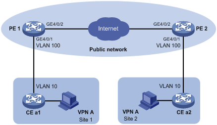
As shown in Figure 4, two VPN A branches, Site 1 and Site 2, are in VLAN 10. The two sites use VPN access services of a service provider. The service provider assigns VLAN 100 to Site 1 and Site 2.
Configure one-to-two VLAN mapping to enable the two branches to communicate across the SP network.
Configuration procedure
1. Configure PE 1:
# Configure a class named test to match traffic tagged with CVLAN 10.
<PE1> system-view
[PE1] traffic classifier test
[PE1-classifier-test] if-match customer-vlan-id 10
[PE1-classifier-test] quit
# Configure a behavior named test to tag traffic with SVLAN tag 100.
[PE1] traffic behavior test
[PE1-behavior-test] nest top-most vlan 100
[PE1-behavior-test] quit
# Create a QoS policy named test, and associate class test with behavior test in the QoS policy.
[PE1] qos policy test
[PE1-qospolicy-test] classifier test behavior test
[PE1-qospolicy-test] quit
# Configure customer-side port GigabitEthernet 4/0/1 as a hybrid port, and assign it to VLAN 100 as an untagged member.
[PE1] interface GigabitEthernet 4/0/1
[PE1-GigabitEthernet4/0/1] port link-type hybrid
[PE1-GigabitEthernet4/0/1] port hybrid vlan 100 untagged
# Apply uplink policy test to the incoming traffic of customer-side port GigabitEthernet 4/0/1.
[PE1-GigabitEthernet4/0/1] qos apply policy test inbound
[PE1-GigabitEthernet4/0/1] quit
# Configure network-side port GigabitEthernet 4/0/2 as a trunk port, and assign it to VLAN 100.
[PE1] interface GigabitEthernet 4/0/2
[PE1-GigabitEthernet4/0/2] port link-type trunk
[PE1-GigabitEthernet4/0/2] port trunk permit vlan 100
[PE1-GigabitEthernet4/0/2] quit
2. Configure PE 2 in the same way as you configure PE 1. (Details not shown.)
Verifying the configuration
# Display the VLAN mapping information on PE1.
Interface GigabitEthernet4/0/1:
[Record 1]
Action : Nest
Dot1p : Inner
Outer VLAN : 1
Inner VLAN : 1 to 9, 11 to 4094
[Record 2]
Action : Nest
Dot1p : Inner
Outer VLAN : 100
Inner VLAN : 10
The output shows that the customer-side port GigabitEthernet 4/0/1 of PE1 adds outer VLAN tag 100 to packets carrying inner VLAN tag 10. The VLAN mapping information on PE2 is the same as PE1.
application scenario
VLAN one-to-two mapping, 2
configuring
VLAN mapping, 1
VLAN one-to-two mapping, 3, 4
VLAN one-to-two mapping customer-side port, 3
VLAN one-to-two mapping network-side port, 4
VLAN one-to-two mapping uplink policy, 3
customer-side port configuration, 3
CVLAN
VLAN mapping concepts and terms, 1
VLAN mapping configuration, 1
VLAN mapping one-to-two application scenario, 1
VLAN one-to-two mapping configuration, 3, 4
VLAN one-to-two mapping customer-side port configuration, 3
VLAN one-to-two mapping implementation, 2
VLAN one-to-two mapping network-side port configuration, 4
VLAN one-to-two mapping uplink policy configuration, 3
displaying VLAN mapping, 4
implementing VLAN one-to-two mapping, 2
network
VLAN one-to-two mapping customer-side port configuration, 3
VLAN one-to-two mapping network-side port configuration, 4
VLAN one-to-two mapping uplink policy configuration, 3
network management
VLAN mapping concepts and terms, 1
VLAN mapping configuration, 1
VLAN mapping one-to-two application scenario, 1
VLAN one-to-two mapping configuration, 3, 4
VLAN one-to-two mapping implementation, 2
network-side port configuration, 4
one-to-two VLAN mapping
application scenario, 1, 2
configuration, 3, 4
customer-side port configuration, 3
network-side port configuration, 4
uplink policy configuration, 3
packet
VLAN mapping concepts and terms, 1
VLAN mapping configuration, 1
VLAN mapping one-to-two application scenario, 1
VLAN one-to-two mapping configuration, 3, 4
VLAN one-to-two mapping customer-side port configuration, 3
VLAN one-to-two mapping implementation, 2
VLAN one-to-two mapping network-side port configuration, 4
VLAN one-to-two mapping uplink policy configuration, 3
port
customer-side configuration, 3
network-side configuration, 4
procedure
configuring VLAN one-to-two mapping, 3, 4
configuring VLAN one-to-two mapping customer-side port, 3
configuring VLAN one-to-two mapping network-side port, 4
configuring VLAN one-to-two mapping uplink policy, 3
displaying VLAN mapping, 4
SVLAN
VLAN mapping concepts and terms, 1
VLAN mapping configuration, 1
VLAN mapping one-to-two application scenario, 1
VLAN one-to-two mapping configuration, 3, 4
VLAN one-to-two mapping customer-side port configuration, 3
VLAN one-to-two mapping implementation, 2
VLAN one-to-two mapping network-side port configuration, 4
VLAN one-to-two mapping uplink policy configuration, 3
tag
VLAN mapping concepts and terms, 1
VLAN mapping configuration, 1
VLAN mapping one-to-two application scenario, 1
VLAN one-to-two mapping configuration, 3, 4
VLAN one-to-two mapping customer-side port configuration, 3
VLAN one-to-two mapping implementation, 2
VLAN one-to-two mapping network-side port configuration, 4
VLAN one-to-two mapping uplink policy configuration, 3
uplink policy configuration, 3
VLAN mapping
concepts and terms, 1
configuration, 1
displaying, 4
one-to-two application scenario, 1
one-to-two configuration, 3, 4
one-to-two customer-side port configuration, 3
one-to-two implementation, 2
one-to-two network-side port configuration, 4
one-to-two uplink policy configuration, 3
VLAN one-to-two mapping
application scenario, 1
configuration, 3, 4
customer-side port configuration, 3
network-side port configuration, 4
uplink policy configuration, 3
VLAN translation. See VLAN mapping