- Table of Contents
-
- 04-Layer 2 - LAN Switching Configuration Guide
- 00-Preface
- 01-MAC address table configuration
- 02-Ethernet link aggregation configuration
- 03-Port isolation configuration
- 04-Spanning tree configuration
- 05-Loop detection configuration
- 06-VLAN configuration
- 07-QinQ configuration
- 08-VLAN mapping configuration
- 09-LLDP configuration
- Related Documents
-
| Title | Size | Download |
|---|---|---|
| 06-VLAN configuration | 175.48 KB |
Contents
Configuring basic VLAN settings
Configuring basic settings of a VLAN interface
Introduction to port-based VLAN
Assigning an access port to a VLAN
Assigning a trunk port to a VLAN
Assigning a hybrid port to a VLAN
Displaying and maintaining VLANs
This chapter provides an overview of VLANs and explains how to configure them.
Overview
Ethernet is a family of shared-media LAN technologies based on the CSMA/CD mechanism. An Ethernet LAN is both a collision domain and a broadcast domain. As the medium is shared, collisions and broadcasts are common in an Ethernet LAN. Typically, bridges and Layer 2 switches can reduce collisions in an Ethernet LAN, but to confine broadcasts, a Layer 2 switch must use the Virtual Local Area Network (VLAN) technology.
VLANs enable a Layer 2 switch to break a LAN down into smaller broadcast domains, as shown in Figure 1.
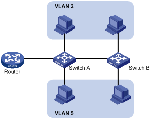
A VLAN is logically divided on an organizational basis rather than on a physical basis. For example, you can assign all workstations and servers used by a particular workgroup to the same VLAN, regardless of their physical locations. Hosts in the same VLAN can directly communicate with one another. You need a router or a Layer 3 switch for hosts in different VLANs to communicate with one another.
All these VLAN features reduce bandwidth waste, improve LAN security, and enable flexible virtual group creation.
VLAN frame encapsulation
To identify Ethernet frames from different VLANs, IEEE 802.1Q inserts a 4-byte VLAN tag between the destination and source MAC address (DA&SA) field and the upper layer protocol type (Type) field, as shown in Figure 2.
Figure 2 VLAN tag placement and format
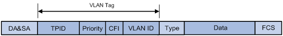
A VLAN tag includes the following fields:
· TPID—16-bit tag protocol identifier that indicates whether a frame is VLAN-tagged. By default, the TPID value is 0x8100, indicating that the frame is VLAN-tagged. However, device vendors can set TPID to different values. For compatibility with neighbor devices, configure the TPID value on the device to be the same as the neighbor device.
· Priority—3-bit long 802.1p priority of the frame. For more information, see ACL and QoS Configuration Guide.
· CFI—1-bit long canonical format indicator that indicates whether the MAC addresses are encapsulated in the standard format when packets are transmitted across different media. Value 0 (the default) indicates that the MAC addresses are encapsulated in the standard format. Value 1 indicates that MAC addresses are encapsulated in a non-standard format. The CFI is 0 in Ethernet.
· VLAN ID—12-bit long, identifies the VLAN that the frame belongs to. The VLAN ID range is 0 to 4095. VLAN IDs 0 and 4095 are reserved, and VLAN IDs 1 to 4094 are user configurable.
A network device handles an incoming frame depending on whether the frame is VLAN tagged and the value of the VLAN tag, if any. For more information, see "Introduction to port-based VLAN."
Ethernet supports encapsulation formats Ethernet II, 802.3/802.2 LLC, 802.3/802.2 SNAP, and 802.3 raw. The Ethernet II encapsulation format is used here. For how the VLAN tag fields are added to frames encapsulated in the other formats for VLAN identification, see related protocols and standards.
For a frame with multiple VLAN tags, the device handles it according to its outer-most VLAN tag and transmits its inner VLAN tags as payload.
Protocols and standards
IEEE 802.1Q, IEEE Standard for Local and Metropolitan Area Networks: Virtual Bridged Local Area Networks
Configuring basic VLAN settings
|
Step |
Command |
Remarks |
|
1. Enter system view. |
system-view |
N/A |
|
2. (Optional.) Create a VLAN and enter its view, or create a list of VLANs. |
vlan { vlan-id1 [ to vlan-id2 ] | all } |
By default, only the default VLAN (VLAN 1) exists. |
|
3. Enter VLAN view. |
vlan vlan-id |
To configure a specific VLAN after you create a list of VLANs, you must perform this step. |
|
4. Configure a name for the VLAN. |
name text |
By default, VLAN names are in the format VLAN vlan-id. For example, the name of VLAN 100 is VLAN 0100 by default. |
|
5. Configure the description of the VLAN. |
description text |
The default setting is VLAN vlan-id, which is the ID of the VLAN. For example, the description of VLAN 100 is VLAN 0100 by default. |
|
|
NOTE: · As the default VLAN, VLAN 1 cannot be created or removed. · You cannot use the undo vlan command to delete a dynamic VLAN, a VLAN with a QoS policy applied, or a VLAN locked by an application. To delete such a VLAN, first remove the configuration from the VLAN. |
Configuring basic settings of a VLAN interface
For hosts of different VLANs to communicate at Layer 3, you can use VLAN interfaces. VLAN interfaces are virtual interfaces used for Layer 3 communication between different VLANs. They do not exist as physical entities on devices. For each VLAN, you can create one VLAN interface. You can assign the VLAN interface an IP address and specify it as the gateway of the VLAN to forward packets destined for an IP subnet different from that of the VLAN.
Before you create a VLAN interface for a VLAN, create the VLAN first.
To configure basic settings of a VLAN interface:
|
Step |
Command |
Remarks |
|
1. Enter system view. |
system-view |
N/A |
|
2. Create a VLAN interface and enter VLAN interface view. |
interface vlan-interface vlan-interface-id |
If the VLAN interface already exists, you enter its view directly. |
|
3. Assign an IP address to the VLAN interface. |
ip address ip-address { mask | mask-length } [ sub ] |
By default, no IP address is assigned to any VLAN interface. |
|
4. Configure the description of the VLAN interface. |
description text |
The default setting is the VLAN interface name. For example, Vlan-interface1 Interface. |
|
5. Configure the MTU for the VLAN interface. |
mtu size |
The default setting is 1500 bytes. |
|
6. (Optional.) Restore the default settings for the VLAN interface. |
default |
N/A |
|
7. (Optional.) Cancel the action of manually shutting down the VLAN interface. |
undo shutdown |
By default, a VLAN interface is manually shut down. After you cancel the action of manually shutting down a VLAN interface, the VLAN interface is up if one or more ports in the VLAN is up, and goes down if all ports in the VLAN go down. |
Configuring port-based VLANs
Introduction to port-based VLAN
Port-based VLANs group VLAN members by port. A port forwards packets for a VLAN only after it is assigned to the VLAN.
Port link type
You can configure the link type of a port as access, trunk, or hybrid. The link types use the following VLAN tag handling methods:
· An access port belongs to only one VLAN and sends packets untagged.
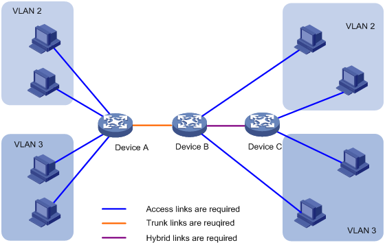
It is usually used to connect a terminal device unable to recognize VLAN-tagged packets or when there is no need to separate different VLAN members. As shown in Figure 3, Device A is connected to common PCs that cannot recognize VLAN-tagged packets, and you must configure Device A’s ports that connect to the PCs as access ports.
· A trunk port can carry multiple VLANs to receive and send packets for them.
Except packets from the port VLAN ID (PVID), packets sent through a trunk port will be VLAN-tagged. Usually, ports connecting network devices are configured as trunk ports. As shown in Figure 3, Device A and Device B need to transmit packets of VLAN 2 and VLAN 3, and you must configure the ports interconnecting Device A and Device B as trunk ports and assign them to VLAN 2 and VLAN 3.
· A hybrid port allows traffic of some VLANs to pass through untagged and traffic of some other VLANs to pass through tagged.
Usually, hybrid ports are configured to connect devices whose support for identifying VLAN-tagged packets is uncertain. As shown in Figure 3, Device C connects to a small-sized LAN in which some PCs belong to VLAN 2 and other PCs belong to VLAN 3. If you are uncertain about that Device C supports identifying VLAN-tagged packets, you can configure on Device B the port connecting to Device C as a hybrid port to allow packets of VLAN 2 and VLAN 3 to pass through untagged.
Figure 3 Network diagram for port link type configuration
PVID
By default, VLAN 1 is the PVID for all ports. You can configure the PVID for a port, as required.
Use the following guidelines when configuring the PVID on a port:
· An access port can join only one VLAN. The VLAN to which the access port belongs is the PVID of the port.
· A trunk or hybrid port can carry multiple VLANs, and you can configure a PVID for the port.
· You can use a nonexistent VLAN as the PVID for a hybrid or trunk port, but not for an access port. After you remove the VLAN that an access port resides in with the undo vlan command, the PVID of the port changes to VLAN 1. However, the removal of the VLAN specified as the PVID of a trunk or hybrid port does not affect the PVID setting on the port.
H3C recommends setting the same PVID for local and remote ports.
Make sure a port is assigned to its PVID. Otherwise, when the port receives frames tagged with the PVID or untagged frames, the port filters out these frames.
How ports of different link types handle frames
|
Actions |
Access |
Trunk |
Hybrid |
|
|
In the inbound direction for an untagged frame |
Tags the frame with the PVID tag. |
· If the PVID is permitted on the port, tags the frame with the PVID tag. · If not, drops the frame. |
||
|
In the inbound direction for a tagged frame |
· Receives the frame if its VLAN ID is the same as the PVID. · Drops the frame if its VLAN ID is different from the PVID. |
· Receives the frame if its VLAN is permitted on the port. · Drops the frame if its VLAN is not permitted on the port. |
||
|
In the outbound direction |
Removes the VLAN tag and sends the frame. |
· Removes the tag and sends the frame if the frame carries the PVID tag and the port belongs to the PVID. · Sends the frame without removing the tag if its VLAN is carried on the port but is different from the PVID. |
Sends the frame if its VLAN is permitted on the port. The frame is sent with the VLAN tag removed or intact depending on your configuration with the port hybrid vlan command. This is true of the PVID. |
|
Assigning an access port to a VLAN
You can assign an access port to a VLAN in VLAN view or interface view.
Make sure the VLAN has been created.
To assign one or multiple access ports to a VLAN in VLAN view:
|
Step |
Command |
Remarks |
|
1. Enter system view. |
system-view |
N/A |
|
2. Enter VLAN view. |
vlan vlan-id |
N/A |
|
3. Assign one or a group of access ports to the VLAN. |
port interface-list |
By default, all ports belong to VLAN 1. |
To assign an access port in interface view to a VLAN:
|
Step |
Command |
Remarks |
|
1. Enter system view. |
system-view |
N/A |
|
2. Enter interface view. |
·
Enter Layer 2 Ethernet interface view: ·
Enter Layer 2 aggregate interface view: |
Use one of the commands. · The configuration made in Layer 2 Ethernet interface view applies only to the port. · The configuration made in Layer 2 aggregate interface view applies to the aggregate interface and its aggregation member ports. If the system fails to apply the configuration to an aggregation member port, it skips the port and moves to the next member port. If the system fails to apply the configuration to the aggregate interface, it stops applying the configuration to aggregation member ports. |
|
3. Configure the link type of the ports as access. |
port link-type access |
By default, all ports are access ports. |
|
4. (Optional.) Assign the access ports to a VLAN. |
port access vlan vlan-id |
By default, all access ports belong to VLAN 1. |
Assigning a trunk port to a VLAN
A trunk port can carry multiple VLANs. You can assign it to a VLAN in interface view.
When you assign a trunk port to a VLAN, follow these guidelines:
· To change the link type of a port from trunk to hybrid or vice versa, set the link type to access first.
· You must configure the trunk port to allow packets from the PVID to pass through by using the port trunk permit vlan command.
To assign a trunk port to one or multiple VLANs:
|
Step |
Command |
Remarks |
|
1. Enter system view. |
system-view |
N/A |
|
2. Enter interface view. |
·
Enter Layer 2 Ethernet interface view: ·
Enter Layer 2 aggregate interface view: |
Use one of the commands. · The configuration made in Layer 2 Ethernet interface view applies only to the port. · The configuration made in Layer 2 aggregate interface view applies to the aggregate interface and its aggregation member ports. If the system fails to apply the configuration to an aggregation member port, it skips the port and moves to the next member port. If the system fails to apply the configuration to the aggregate interface, it stops applying the configuration to aggregation member ports. |
|
3. Configure the link type of the ports as trunk. |
port link-type trunk |
By default, all ports are access ports. |
|
4. Assign the trunk ports to the specified VLANs. |
port trunk permit vlan { vlan-list | all } |
By default, a trunk port only permits VLAN 1. |
|
5. (Optional.) Configure the PVID of the trunk ports. |
port trunk pvid vlan vlan-id |
The default setting is VLAN 1. |
Assigning a hybrid port to a VLAN
A hybrid port can carry multiple VLANs. You can assign it to the specified VLANs in interface view. Make sure the VLANs have been created.
When you assign a hybrid port to a VLAN, follow these guidelines:
· To change the link type of a port from trunk to hybrid or vice versa, set the link type to access first.
· You must configure the hybrid port to allow packets from the PVID to pass through by using the port hybrid vlan command.
To assign a hybrid port to one or multiple VLANs:
|
Step |
Command |
Remarks |
|
1. Enter system view. |
system-view |
N/A |
|
2. Enter interface view. |
·
Enter Layer 2 Ethernet interface view: ·
Enter Layer 2 aggregate interface view: |
Use one of the commands. · The configuration made in Layer 2 Ethernet interface view applies only to the port. · The configuration made in Layer 2 aggregate interface view applies to the aggregate interface and its aggregation member ports. If the system fails to apply the configuration to an aggregation member port, it skips the port and moves to the next member port. If the system fails to apply the configuration to the aggregate interface, it stops applying the configuration to aggregation member ports. |
|
3. Configure the link type of the ports as hybrid. |
port link-type hybrid |
By default, all ports are access ports. |
|
4. Assign the hybrid ports to the specified VLANs. |
port hybrid vlan vlan-list { tagged | untagged } |
By default, a hybrid port allows only packets of VLAN 1 to pass through untagged. |
|
5. (Optional.) Configure the PVID of the hybrid ports. |
port hybrid pvid vlan vlan-id |
The default setting is VLAN 1. |
Displaying and maintaining VLANs
Execute display commands in any view and reset commands in user view.
|
Task |
Command |
|
Display VLAN information. |
display vlan [ vlan-id1 [ to vlan-id2 ] | all | dynamic | reserved | static ] |
|
Display VLAN interface information. |
display interface vlan-interface [ vlan-interface-id ] [ brief [ description ] ] |
|
Display hybrid ports or trunk ports on the device. |
display port { hybrid | trunk } |
|
Clear statistics on a port. |
reset counters interface vlan-interface [ vlan-interface-id ] |
Port-based VLAN configuration example
|
|
IMPORTANT: By default, Ethernet interfaces, VLAN-interfaces, and aggregate interfaces are down. To configure these interfaces, first bring up these interfaces by using the undo shutdown command. |
Network requirements
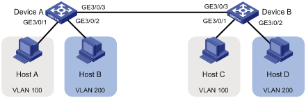
As shown in Figure 4, Host A and Host C belong to Department A, and access the enterprise network through different devices. Host B and Host D belong to Department B. They also access the enterprise network through different devices.
To ensure communication security and avoid broadcast storms, VLANs are configured in the enterprise network to isolate Layer 2 packets of different departments. VLAN 100 is assigned to Department A, and VLAN 200 is assigned to Department B.
Make sure hosts within the same VLAN can communicate with each other: Host A can communicate with Host C, and Host B can communicate with Host D.
Configuration procedure
1. Configure Device A:
# Create VLAN 100, and assign port GigabitEthernet 3/0/1 to VLAN 100.
<DeviceA> system-view
[DeviceA] vlan 100
[DeviceA-vlan100] port GigabitEthernet 3/0/1
[DeviceA-vlan100] quit
# Create VLAN 200, and assign port GigabitEthernet 3/0/2 to VLAN 200.
[DeviceA] vlan 200
[DeviceA-vlan200] port GigabitEthernet 3/0/2
[DeviceA-vlan200] quit
# Configure port GigabitEthernet 3/0/3 as a trunk port, and assign it to VLANs 100 and 200, enabling GigabitEthernet 3/0/3 to forward packets of VLANs 100 and 200 to Device B.
[DeviceA] interface GigabitEthernet 3/0/3
[DeviceA-GigabitEthernet3/0/3] port link-type trunk
[DeviceA-GigabitEthernet3/0/3] port trunk permit vlan 100 200
2. Configure Device B as you configure Device A.
3. Configure hosts:
¡ Configure Host A and Host C to be on the same IP subnet. For example, 192.168.100.0/24.
¡ Configure Host B and Host D to be on the same IP subnet. For example, 192.168.200.0/24.
Verifying the configuration
# Verify that Host A and Host C can ping each other, but they both fail to ping Host B.
# Verify that Host B and Host D can ping each other, but they both fail to ping Host A.
# Verify that VLANs 100 and 200 are correctly configured on Device A.
[DeviceA-GigabitEthernet3/0/3] display vlan 100
VLAN ID: 100
VLAN type: Static
Route interface: Not configured
Description: VLAN 0100
Name: VLAN 0100
Tagged ports:
GigabitEthernet3/0/3
Untagged ports:
GigabitEthernet3/0/1
[DeviceA-GigabitEthernet3/0/3] display vlan 200
VLAN ID: 200
VLAN type: Static
Route interface: Not configured
Description: VLAN 0200
Name: VLAN 0200
Tagged ports:
GigabitEthernet3/0/3
Untagged ports:
GigabitEthernet3/0/2
assigning
access port to a VLAN, 7
hybrid port to a VLAN, 9
trunk port to a VLAN, 8
configuring basic VLAN settings, 3
frame encapsulation, VLAN, 2
port link type, 5
port-based VLAN
configuration example, 10
configuration procedure, 11
how ports of different link types handle frames, 6
introduction, 5
network requirements, 11
port link type, 5
PVID, 6
verifying the configuration, 11
port-based VLANs, 5
procedure
assigning a hybrid port to a VLAN, 9
assigning a trunk port to a VLAN, 8
assigning an access port to a VLAN, 7
configuring basic settings of a VLAN interface, 4
configuring basic VLAN settings, 3
configuring port-based VLANs, 5
configuring VLANs, 2
protocols and standards, VLAN, 3
PVID, 6
VLAN
assigning a hybrid port to a VLAN, 9
assigning a trunk port to a VLAN, 8
assigning an access port to a VLAN, 7
configuration, 2
configuring, 2
configuring basic settings, 3
configuring basic settings of a VLAN interface, 4
configuring port-based VLANs, 5
frame encapsulation, 2
how ports of different link types handle frames, 6
port link type, 5
port-based, 5
port-based VLAN configuration example, 10
port-based VLAN introduction, 5
protocols and standards, 3
PVID, 6
VLAN basic settings, 3
VLAN frame encapsulation, 2
VLAN interface, basic settings, 4