- Table of Contents
-
- 12-High Availability Configuration Guide
- 00-Preface
- 01-High Availability Overview
- 02-Active and Standby Switchover Configuration
- 03-Ethernet OAM Configuration
- 04-CFD Configuration
- 05-DLDP Configuration
- 06-RPR Configuration
- 07-RRPP Configuration
- 08-Smart Link Configuration
- 09-Monitor Link Configuration
- 10-VRRP Configuration
- 11-BFD Configuration
- 12-Track Configuration
- Related Documents
-
| Title | Size | Download |
|---|---|---|
| 09-Monitor Link Configuration | 157.6 KB |
Contents
Configuring monitor link group member ports
Displaying and maintaining Monitor Link
Monitor Link configuration example
Overview
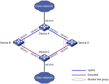
Monitor Link is a port collaboration function. Monitor Link usually works together with Layer 2 topology protocols. The idea is to monitor the states of uplink ports and adapt the up/down state of downlink ports to the up/down state of uplink ports, triggering link switchover on the downstream switch in time, as shown in Figure 1.
Figure 1 Monitor Link application scenario
Terminology
Monitor link group
A monitor link group is a set of uplink and downlink ports. A port can belong to only one monitor link group. As shown in Figure 1, ports GigabitEthernet 3/0/1 and GigabitEthernet 3/0/2 of Device B and those of Device D each form a monitor link group. GigabitEthernet 3/0/1 on both switches are uplink ports, and GigabitEthernet 3/0/2 on both switches are downlink ports.
Uplink/Downlink ports
Uplink port and downlink port are two port roles in monitor link groups:
· Uplink ports refer to the monitored ports. The state of a monitor link group adapts to that of its member uplink ports. When a monitor link group contains no uplink port or all the uplink ports are down, the monitor link group becomes down; as long as one member uplink port is up, the monitor link group stays up.
· Downlink ports refer to the monitoring ports. The state of the downlink ports in a monitor link group adapts to that of the monitor link group. When the state of a monitor link group changes, the state of its member downlink ports change accordingly. In this way, the state of the downlink ports in a monitor link group is always consistent with that of the monitor link group.
Uplink/Downlink
The uplink is the link that connects the uplink ports in a monitor link group, while the downlink is the link that connects the downlink ports.
How Monitor Link works
A monitor link group works independently of other monitor link groups. When a monitor link group contains no uplink port or all its uplink ports are down, the monitor link group goes down and forces all downlink ports down at the same time. When any uplink port goes up, the monitor link group goes up and brings up all the downlink ports.
|
|
CAUTION: H3C does not recommend that you manually shut down or bring up the downlink ports in a monitor link group. |
Configuring Monitor Link
Configuration prerequisites
Make sure the port to be assigned to a monitor link group is not a member port of any aggregation group.
Creating a monitor link group
To create a monitor link group:
|
Step |
Command |
|
1. Enter system view. |
system-view |
|
2. Create a monitor link group and enter monitor link group view. |
monitor-link group group-id |
Configuring monitor link group member ports
You can configure member ports for a monitor link group either in monitor link group view or interface view. The configurations made in these two views lead to the same result.
In monitor link group view
To configure member ports for a monitor link group in monitor link group view:
|
Step |
Command |
Remarks |
|
1. Enter system view. |
system-view |
N/A |
|
2. Enter monitor link group view. |
monitor-link group group-id |
N/A |
|
3. Configure member ports for the monitor link group. |
port interface-type interface-number { uplink | downlink } |
RPR logical interface do not support the downlink keyword. |
In interface view
To configure member ports for a monitor link group in interface view:
|
Step |
Command |
Remarks |
|
1. Enter system view. |
system-view |
N/A |
|
2. Enter Layer 2 Ethernet interface view, Layer 2 aggregate interface view, or RPR logical interface view. |
interface interface-type interface-number |
N/A |
|
3. Configure the current interface as a member of a monitor link group. |
port monitor-link group group-id { uplink | downlink } |
RPR logical interface do not support the downlink keyword. |
|
|
NOTE: · You can assign a Layer 2 Ethernet interface, Layer 2 aggregate interface, or RPR logical interface to a monitor link group as a member port. RPR logical interfaces can only be configured as uplink ports. · A port can be assigned to only one monitor link group. · Configure uplink ports prior to downlink ports to avoid undesired down/up state changes on the downlink ports. |
Displaying and maintaining Monitor Link
|
Task |
Command |
Remarks |
|
Display monitor link group information. |
display monitor-link group { group-id | all } [ | { begin | exclude | include } regular-expression ] |
Available in any view |
Monitor Link configuration example
|
|
NOTE: By default, Ethernet, VLAN, and aggregate interfaces are in DOWN state. Before configuring these interfaces, use the undo shutdown command to bring them up. |
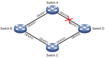
Network requirements
As shown in Figure 2, Switch C is a smart link device, and Switch A, Switch B, and Switch D are associated devices. Traffic of VLANs 1 through 30 on Switch C is dual-uplinked to Switch A through a smart link group.
Implement dual uplink backup on Switch C, and make sure that when the link between Switch A and Switch B (or Switch D) fails, Switch C must be able to sense the link fault and perform uplink switchover in the smart link group.
|
|
NOTE: For more information about the Smart Link feature, see the chapter "Configuring Smart Link." |
Configuration procedure
1. Configure Switch C.
# Create VLANs 1 through 30, map these VLANs to MSTI 1, and activate MST region configuration.
<SwitchC> system-view
[SwitchC] vlan 1 to 30
[SwitchC] stp region-configuration
[SwitchC-mst-region] instance 1 vlan 1 30
[SwitchC-mst-region] active region-configuration
[SwitchC-mst-region] quit
# Disable the spanning tree feature on GigabitEthernet 4/0/1 and GigabitEthernet 4/0/2 separately, configure them as trunk ports, and assign them to VLANs 1 through 30.
[SwitchC] interface gigabitethernet 4/0/1
[SwitchC-GigabitEthernet4/0/1] undo stp enable
[SwitchC-GigabitEthernet4/0/1] port link-type trunk
[SwitchC-GigabitEthernet4/0/1] port trunk permit vlan 1 to 30
[SwitchC-GigabitEthernet4/0/1] quit
[SwitchC] interface gigabitethernet 4/0/2
[SwitchC-GigabitEthernet4/0/2] undo stp enable
[SwitchC-GigabitEthernet4/0/2] port link-type trunk
[SwitchC-GigabitEthernet4/0/2] port trunk permit vlan 1 to 30
[SwitchC-GigabitEthernet4/0/2] quit
# Create smart link group 1, and configure all the VLANs mapped to MSTI 1 as the protected VLANs for smart link group 1.
[SwitchC] smart-link group 1
[SwitchC-smlk-group1] protected-vlan reference-instance 1
# Configure GigabitEthernet 4/0/1 as the master port and GigabitEthernet 4/0/2 as the slave port for smart link group 1.
[SwitchC-smlk-group1] port gigabitethernet 4/0/1 master
[SwitchC-smlk-group1] port gigabitethernet 4/0/2 slave
# Enable the smart link group to transmit flush messages.
[SwitchC-smlk-group1] flush enable
[SwitchC-smlk-group1] quit
2. Configure Switch A.
# Create VLANs 1 through 30.
<SwitchA> system-view
[SwitchA] vlan 1 to 30
# Configure GigabitEthernet 4/0/1 and GigabitEthernet 4/0/2 as trunk ports, assign them to VLANs 1 through 30, and enable flush message receiving on them.
[SwitchA] interface gigabitethernet 4/0/1
[SwitchA-GigabitEthernet4/0/1] port link-type trunk
[SwitchA-GigabitEthernet4/0/1] port trunk permit vlan 1 to 30
[SwitchA-GigabitEthernet4/0/1] smart-link flush enable
[SwitchA-GigabitEthernet4/0/1] quit
[SwitchA] interface gigabitethernet 4/0/2
[SwitchA-GigabitEthernet4/0/2] port link-type trunk
[SwitchA-GigabitEthernet4/0/2] port trunk permit vlan 1 to 30
[SwitchA-GigabitEthernet4/0/2] smart-link flush enable
[SwitchA-GigabitEthernet4/0/2] quit
3. Configure Switch B.
# Create VLANs 1 through 30.
<SwitchB> system-view
[SwitchB] vlan 1 to 30
# Configure GigabitEthernet 4/0/1 and GigabitEthernet 4/0/2 as trunk ports, and assign them to VLANs 1 through 30. Disable the spanning tree feature on GigabitEthernet 4/0/2, and enable flush message receiving on both ports.
[SwitchB] interface gigabitethernet 4/0/1
[SwitchB-GigabitEthernet4/0/1] port link-type trunk
[SwitchB-GigabitEthernet4/0/1] port trunk permit vlan 1 to 30
[SwitchB-GigabitEthernet4/0/1] smart-link flush enable
[SwitchB-GigabitEthernet4/0/1] quit
[SwitchB] interface gigabitethernet 4/0/2
[SwitchB-GigabitEthernet4/0/2] undo stp enable
[SwitchB-GigabitEthernet4/0/2] port link-type trunk
[SwitchB-GigabitEthernet4/0/2] port trunk permit vlan 1 to 30
[SwitchB-GigabitEthernet4/0/2] smart-link flush enable
[SwitchB-GigabitEthernet4/0/2] quit
# Create monitor link group 1, and then configure GigabitEthernet 4/0/1 as an uplink port and GigabitEthernet 4/0/2 as a downlink port for monitor link group 1.
[SwitchB] monitor-link group 1
[SwitchB-mtlk-group1] port gigabitethernet 4/0/1 uplink
[SwitchB-mtlk-group1] port gigabitethernet 4/0/2 downlink
[SwitchB-mtlk-group1] quit
4. Configure Switch D.
# Create VLANs 1 through 30.
<SwitchD> system-view
[SwitchD] vlan 1 to 30
# Configure GigabitEthernet 4/0/1 and GigabitEthernet 4/0/2 as trunk ports, assign them to VLANs 1 through 30. Disable the spanning tree feature on GigabitEthernet 4/0/2, and enable flush message receiving on both ports.
[SwitchD] interface GigabitEthernet4/0/1
[SwitchD-GigabitEthernet4/0/1] port link-type trunk
[SwitchD-GigabitEthernet4/0/1] port trunk permit vlan 1 to 30
[SwitchD-GigabitEthernet4/0/1] smart-link flush enable
[SwitchD-GigabitEthernet4/0/1] quit
[SwitchD] interface GigabitEthernet4/0/2
[SwitchD-GigabitEthernet4/0/2] undo stp enable
[SwitchD-GigabitEthernet4/0/2] port link-type trunk
[SwitchD-GigabitEthernet4/0/2] port trunk permit vlan 1 to 30
[SwitchD-GigabitEthernet4/0/2] smart-link flush enable
[SwitchD-GigabitEthernet4/0/2] quit
# Create monitor link group 1, and then configure GigabitEthernet 4/0/1 as an uplink port and GigabitEthernet 4/0/2 as a downlink port for monitor link group 1.
[SwitchD] monitor-link group 1
[SwitchD-mtlk-group1] port gigabitethernet 4/0/1 uplink
[SwitchD-mtlk-group1] port gigabitethernet 4/0/2 downlink
[SwitchD-mtlk-group1] quit
5. Verify the configuration.
Use the display monitor-link group command display the monitor link group information on devices. For example, when GigabitEthernet 4/0/2 on Switch A goes down due to a link fault:
# Check information about monitor link group 1 on Switch B.
<SwitchB> display monitor-link group 1
Monitor link group 1 information:
Group status: UP
Last-up-time: 16:37:20 2009/4/21
Last-down-time: 16:35:26 2009/4/21
Member Role Status
------------------------------------------
GigabitEthernet4/0/1 UPLINK UP
GigabitEthernet4/0/2 DOWNLINK UP
# Check information about monitor link group 1 on Switch D.
<SwitchD> display monitor-link group 1
Monitor link group 1 information:
Group status: DOWN
Last-up-time: 16:35:27 2009/4/21
Last-down-time: 16:37:19 2009/4/21
Member Role Status
------------------------------------------
GigabitEthernet4/0/1 UPLINK DOWN
GigabitEthernet4/0/2 DOWNLINK DOWN