- Table of Contents
-
- 12-High Availability Configuration Guide
- 00-Preface
- 01-High Availability Overview
- 02-Active and Standby Switchover Configuration
- 03-Ethernet OAM Configuration
- 04-CFD Configuration
- 05-DLDP Configuration
- 06-RPR Configuration
- 07-RRPP Configuration
- 08-Smart Link Configuration
- 09-Monitor Link Configuration
- 10-VRRP Configuration
- 11-BFD Configuration
- 12-Track Configuration
- Related Documents
-
| Title | Size | Download |
|---|---|---|
| 04-CFD Configuration | 250.96 KB |
Configuring basic CFD settings
Configuring the CFD protocol version
Configuring MIP generation rules
Displaying and maintaining CFD
Overview
Connectivity Fault Detection (CFD), which conforms to IEEE 802.1ag Connectivity Fault Management (CFM) and ITU-T Y.1731, is an end-to-end per-VLAN link layer Operations, Administration and Maintenance (OAM) mechanism used for link connectivity detection, fault verification, and fault location.
Basic concepts in CFD
Maintenance domain
A maintenance domain (MD) defines the network or part of the network where CFD plays its role. An MD is identified by its MD name.
To accurately locate faults, CFD introduces eight levels (from 0 to 7) to MDs. The bigger the number, the higher the level and the larger the area covered. Domains can touch or nest (if the outer domain has a higher level than the nested one) but cannot intersect or overlap.
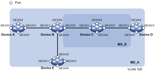
MD levels facilitate fault location and make fault location more accurate. As shown in Figure 1, MD_A in light blue nests MD_B in dark blue. If a connectivity fault is detected at the boundary of MD_A, any of the devices in MD_A, including Device A through Device E, may fail. If a connectivity fault is also detected at the boundary of MD_B, the failure points may be any of Device B through Device D. If the devices in MD_B can operate properly, at least Device C is operational.
CFD exchanges messages and performs operations on a per-domain basis. By planning MDs properly in a network, you can use CFD to rapidly locate failure points.
Maintenance association
A maintenance association (MA) is a part of an MD. You can configure multiple MAs in an MD as needed. An MA is identified by the “MD name + MA name”.
An MA serves a VLAN. Packets sent by the MPs in an MA carry the relevant VLAN tag. An MP can receive packets sent by other MPs in the same MA. The level of an MA equals the level of the MD that the MA belongs to.
Maintenance point
An MP is configured on a port and belongs to an MA. MPs fall into two types: maintenance association end points (MEPs) and maintenance association intermediate points (MIPs).
· MEP
MEPs define the boundary of the MD. Each MEP is identified by an MEP ID.
The MA that a MEP belongs to defines the VLAN of packets sent by the MEP; the level of an MEP equals the level of the MD that the MEP belongs to, and the level of packets sent by an MEP equals the level of the MEP. The level of a MEP determines the levels of packets that the MEP can process. A MEP forwards packets at a higher level and processes packet of its level or lower. The processing procedure is specific to packets in the same VLAN. Packets of different VLANs are independent.
MEPs fall into inward-facing MEPs and outward-facing MEPs. An outward-facing MEP sends packets to its host port. An inward-facing MEP does not send packets to its host port. Rather, it sends packets to other ports on the device.
· MIP
A MIP is internal to an MD. It cannot send CFD packets actively; however, it can handle and respond to CFD packets. By cooperating with MEPs, a MIP can perform a function similar to ping and traceroute. A MIP forwards packets of a different level without any processing and only processes packet of its level.
The MA that a MIP belongs to defines the VLAN of packets that the MEP can receive; the level of a MIP is defined by its generation rule and the MD that the MIP belongs to. MIPs are generated on each port automatically according to related MIP generation rules. If a port has no MIP, the system will check the MAs in each MD (from low to high levels), and follow the procedure as described in Figure 2 to create or not to create MIPs at the relevant level.
Figure 2 Procedure of creating MIPs
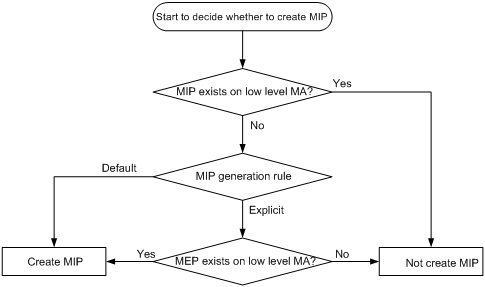
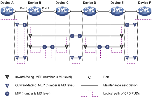
Figure 3 demonstrates a grading example of the CFD module. Four levels of MDs (0, 2, 3, and 5) are designed. The bigger the number, the higher the level and the larger the area covered. MPs are configured on the ports of device A through device F. Port 1 of device B is configured with the following MPs—a level 5 MIP, a level 3 inward-facing MEP, a level 2 inward-facing MEP, and a level 0 outward-facing MEP.
MEP list
A MEP list is a collection of local MEPs allowed to be configured and the remote MEPs to be monitored in the same MA. It lists all the MEPs configured on different devices in the same MA. The MEPs all have unique MEP IDs. When a MEP receives from a remote device a continuity check message (CCM) that carries a MEP ID not included in the MEP list of the MA, it drops the message.
CFD functions
CFD works effectively only in properly-configured networks. Its functions, which are implemented through the MPs, include:
· Continuity check (CC)
· Loopback (LB)
· Linktrace (LT)
· Alarm indication signal (AIS)
· Loss measurement (LM)
· Delay measurement (DM)
· Test (TST)
Continuity check
Connectivity faults are usually caused by device faults or configuration errors. Continuity check checks the connectivity between MEPs. This function is implemented through periodic sending of continuity check messages (CCMs) by the MEPs. A CCM sent by one MEP is intended to be received by all the other MEPs in the same MA. If a MEP fails to receive the CCMs within 3.5 times the sending interval, the link is considered as faulty and a log is generated. When multiple MEPs send CCMs at the same time, the multipoint-to-multipoint link check is achieved. CCM frames are multicast frames.
Loopback
Similar to ping at the IP layer, loopback verifies the connectivity between a source device and a target device. To implement this function, the source MEP sends loopback messages (LBMs) to the target MEP. Depending on whether the source MEP can receive a loopback reply message (LBR) from the target MEP, the link state between the two can be verified. LBM frames and LBR frames are unicast frames.
Linktrace
Linktrace is similar to traceroute. It identifies the path between the source MEP and the target MEP. This function is implemented in the following way—the source MEP sends the linktrace messages (LTMs) to the target MEP. After receiving the messages, the target MEP and the MIPs that the LTM frames pass send back linktrace reply messages (LTRs) to the source MEP. Based on the reply messages, the source MEP can identify the path to the target MEP. LTM frames are multicast frames and LTRs are unicast frames.
AIS
The AIS function suppresses the number of error alarms reported by MEPs. If a local MEP receives no CCM frames from its peer MEP within 3.5 times the CCM transmission interval, it immediately starts to send AIS frames periodically in the opposite direction of CCM frames. Upon receiving the AIS frames, the peer MEP suppresses the error alarms locally, and continues to send the AIS frames. If the local MEP receives CCM frames within 3.5 times the CCM transmission interval, it stops sending AIS frames and restores the error alarm function. AIS frames are multicast frames.
TST
The TST function tests the bit errors between two MEPs. The source MEP sends a TST frame, which carries the test pattern, such as pseudo random bit sequence (PRBS) or all-zero, to the target MEP. Upon receiving the TST frame, the target MEP determines the bit errors by calculating and comparing the content of the TST frame. TST frames are unicast frames.
Protocols and standards
· IEEE 802.1ag, Virtual Bridged Local Area Networks Amendment 5: Connectivity Fault Management
· ITU-T Y.1731, OAM functions and mechanisms for Ethernet based networks
CFD configuration task list
For CFD to work properly, design the network by performing the following tasks:
· Grade the MDs in the entire network, and define the boundary of each MD
· Assign a name for each MD. Make sure that the same MD has the same name on different devices.
· Define the MA in each MD according to the VLAN you want to monitor
· Assign a name for each MA. Make sure that the same MA in the same MD has the same name on different devices.
· Determine the MEP list of each MA in each MD. Make sure that devices in the same MA maintain the same MEP list.
· At the edges of MD and MA, MEPs should be designed at the device port. MIPs can be designed on devices or ports that are not at the edges.
Complete the following tasks to configure CFD:
|
Tasks |
Remarks |
||
|
Required |
|||
|
Optional |
|||
|
Required Perform either task |
|||
|
Required |
|||
|
Required |
|||
|
Required |
|||
|
Optional |
|||
|
Optional |
|||
|
Optional |
|||
|
Optional |
|||
|
|
NOTE: Typically, a port blocked by the spanning tree feature cannot receive or send CFD messages except in the following cases: · The port is configured as an outward-facing MEP. · The port is configured as a MIP or inward-facing MEP, which can still receive and send CFD messages except CCM messages. For more information about the spanning tree feature, see Layer 2—LAN Switching Configuration Guide. |
Configuring basic CFD settings
Enabling CFD
H3C recommends that you enable CFD before performing other CFD configuration tasks.
To enable CFD on a device:
|
Step |
Command |
Remarks |
|
1. Enter system view. |
system-view |
N/A |
|
2. Enable CFD. |
cfd enable |
By default, CFD is disabled. |
Configuring the CFD protocol version
Three CFD protocol versions are available: IEEE 802.1ag draft5.2 version, IEEE 802.1ag draft5.2 interim version, and IEEE 802.1ag standard version. Devices in a same MD must use the same CFD protocol version; otherwise, they cannot exchange CFD protocol packets.
To configure the CFD protocol version:
|
Step |
Command |
Remarks |
|
1. Enter system view. |
system-view |
N/A |
|
2. Configure the CFD protocol version. |
cfd version { draft5 | draft5-plus | standard } |
Optional. By default, CFD uses the standard version of IEEE 802.1ag. |
|
|
NOTE: If an MD is created by using the cfd md command or automatically generated by using the cfd service-instance maid format command on a device, you cannot switch between the standard version and draft5.2 version (or draft5.2 interim version); however, you can switch between the draft5.2 version and draft5.2 interim version. This restriction does not apply to the device without an MD configured. |
Configuring service instances
Before configuring the MEPs and MIPs, you must first configure service instances. A service instance is a set of service access points (SAPs), and belongs to an MA in an MD.
A service instance is indicated by an integer to represent an MA in an MD. The MD and MA define the level and VLAN attribute of the messages handled by the MPs in a service instance.
Service instances fall into the following types:
· Service instance with the MD name, which takes effect in any version of CFD.
· Service instance without the MD name, which takes effect in only CFD IEEE 802.1ag.
You can create either type of service instance as needed.
Creating a service instance with the MD name
To create a service instance with the MD name, create the MD and MA for the service instance first.
To configure a service instance with the MD name:
|
Step |
Command |
Remarks |
|
1. Enter system view. |
system-view |
N/A |
|
2. Create an MD. |
cfd md md-name level level-value |
By default, no MD is created. |
|
3. Create an MA. |
cfd ma ma-name md md-name vlan vlan-id |
By default, no MA is created. |
|
4. Create a service instance with the MD name. |
cfd service-instance instance-id md md-name ma ma-name |
By default, no service instance is created. |
Creating a service instance without the MD name
When you create a service instance without the MD name, the system automatically creates the MA and MD for the service instance.
To create a service instance without the MD name:
|
Step |
Command |
Remarks |
|
1. Enter system view. |
system-view |
N/A |
|
2. Create a service instance without the MD name. |
cfd service-instance instance-id maid format { icc-based ma-name | string ma-name } level level-value vlan vlan-id |
By default, no service instance is created. |
Configuring MEPs
CFD is implemented through various operations on MEPs. As a MEP is configured on a service instance, the MD level and VLAN attribute of the service instance become the attribute of the MEP.
Before creating MEPs, configure the MEP list first. An MEP list is a collection of local MEPs allowed to be configured in an MA and the remote MEPs to be monitored.
To configure a MEP:
|
Step |
Command |
Remarks |
|
1. Enter system view. |
system-view |
N/A |
|
2. Configure a MEP list. |
cfd meplist mep-list service-instance instance-id |
By default, no MEP list is configured. |
|
3. Enter Layer 2 Ethernet interface view. |
interface interface-type interface-number |
N/A |
|
4. Create a MEP. |
cfd mep mep-id service-instance instance-id { inbound | outbound } |
By default, no MEP is configured. |
|
5. Enable the MEP. |
cfd mep service-instance instance-id mep mep-id enable |
By default, the MEP is disabled. |
|
|
CAUTION: You cannot create a MEP if the MEP ID is not included in the MEP list of the service instance. |
Configuring MIP generation rules
As functional entities in a service instance, MIPs respond to various CFD frames, such as LTM frames, LBM frames, 1DM frames, DMM frames, and TST frames. You can choose appropriate MIP generation rules based on your network design.
To configure the rules for generating MIPs:
|
Step |
Command |
Remarks |
|
1. Enter system view. |
system-view |
N/A |
|
2. Configure the rules for generating MIPs. |
cfd mip-rule { explicit | default } service-instance instance-id |
By default, neither MIPs nor the rules for generating MIPs are configured. |
|
|
CAUTION: Any of the following actions or cases can cause MIPs to be created or deleted after you have configured the cfd mip-rule command: · Enabling CFD (use the cfd enable command) · Creating or deleting the MEPs on a port · Changes occur to the VLAN attribute of a port · The rule specified in the cfd mip-rule command changes |
Configuring CFD functions
Configuration prerequisites
Complete basic CFD settings.
Configuring CC on MEPs
You must configure CC before configuring other CFD functions. After the CC function is configured, MEPs can send CCM frames to one another to check the connectivity between them.
|
The interval field value in the CCM messages |
The interval between CCM messages |
The timeout time of the remote MEP |
|
2 |
10 milliseconds |
35 milliseconds |
|
3 |
100 milliseconds |
350 milliseconds |
|
4 |
1 second |
3.5 seconds |
|
5 |
10 second |
35 seconds |
|
6 |
60 seconds |
210 seconds |
|
7 |
600 seconds |
2100 seconds |
|
|
NOTE: The following describes CCM messages with the interval field value 2 to 3 as high-speed CCM messages, and those with the interval field 4 to 7 as low-speed CCM messages. |
To configure CC on a MEP:
|
Step |
Command |
Remarks |
|
1. Enter system view. |
system-view |
N/A |
|
2. Configure the interval field value in the CCM messages sent by MEPs. |
cfd cc interval interval-value service-instance instance-id |
Optional. By default, the interval field value is 4. |
|
3. Enter Layer 2 Ethernet interface view. |
interface interface-type interface-number |
N/A |
|
4. Enable CCM sending on a MEP. |
cfd cc service-instance instance-id mep mep-id enable |
By default, CCM sending on a MEP is disabled. |
|
|
NOTE: · Only the MPUs with silkscreen LSR1SRP2C1, LSR1SRP2C2, or LSR1SRP2D1 have assistant CPUs. · If the switch has two MPUs with assistant CPUs, the CCM frames will be sent by the active MPU. If the active MPU is unplugged, the standby MPU will take over to send CCM frames and CC will be re-performed. · If the switch has one MPU with an assistant CPU, the CCM frames will be sent by this MPU. · If the switch has no MPUs with assistant CPUs, the CCM frames will be sent by the card where the MEP is located. The card sends and receives only low-speed CCM messages, and discards high-speed CCM messages. |
|
|
CAUTION: · You must configure the same interval field value in CCM messages sent by the MEPs belonging to the same MA. · If the devices where all MEPs belonging to the same MA are located have assistant CPUs, the MEPs can send and receive high-speed CCM messages properly; otherwise, configure the same interval field value to make all MEPs in the MA send low-speed CCM messages. |
Configuring LB on MEPs
The LB function can verify the link state between the local MEP and the remote MEP or MIP.
To configure LB on a MEP:
|
Task |
Command |
Remarks |
|
Enable LB. |
cfd loopback service-instance instance-id mep mep-id { target-mep target-mep-id | target-mac mac-address } [ number number ] |
By default, LB is disabled. Available in any view. |
Configuring LT on MEPs
LT can trace the path between the source and target MEPs, and can also locate link faults by sending LT messages automatically. The two functions are implemented in the following way:
· To implement the first function, the source MEP first sends LTM messages to the target MEP. Based on the LTR messages in response to the LTM messages, the path between the two MEPs can be identified.
· In the latter case, after LT messages automatic sending is enabled, if the source MEP fails to receive the CCM frames from the target MEP within 3.5 times the transmission interval, the link between the two is considered faulty and LTM frames (with the target MEP as the destination and the TTL field in the LTM frames set to the maximum value 255) will be sent out. Based on the LTRs that the MIPs return, the fault source can be located.
To configure LT on MEPs:
|
Step |
Command |
Remarks |
|
1. Find the path between a source MEP and a target MEP. |
cfd linktrace service-instance instance-id mep mep-id { target-mep target-mep-id | target-mac mac-address } [ ttl ttl-value ] [ hw-only ] |
Available in any view |
|
2. Enter system view. |
system-view |
N/A |
|
3. Enable LT messages automatic sending. |
cfd linktrace auto-detection [ size size-value ] |
By default, LT messages automatic sending is disabled. |
Configuring AIS
The AIS function suppresses the number of error alarms reported by MEPs.
To configure AIS:
|
Step |
Command |
Remarks |
|
1. Enter system view. |
system-view |
N/A |
|
2. Enable AIS. |
cfd ais enable |
By default, AIS is disabled. |
|
3. Configure the AIS frame transmission level. |
cfd ais level level-value service-instance instance-id |
By default, the AIS frame transmission level is not configured. |
|
4. Configure the AIS frame transmission interval. |
cfd ais period period-value service-instance instance-id |
Optional The default is 1 second. |
|
|
CAUTION: · Enable AIS and configure the proper AIS frame transmission level on the target MEP, so the target MEP can suppress the error alarms and send the AIS frame to the MD of a higher level. If you enable AIS but do not configure the proper AIS frame transmission level on the target MEP, the target MEP can suppress the error alarms, but cannot send the AIS frames. |
Configuring TST
The TST function detects bit errors on a link, and monitors and manages the link transmission performance.
To configure TST:
|
Step |
Command |
Remarks |
|
1. Enter system view. |
system-view |
N/A |
|
2. Configure TST. |
cfd tst service-instance instance-id mep mep-id { target-mac mac-address | target-mep target-mep-id } [ number number ] [ length-of-test length ] [ pattern-of-test { all-zero | prbs } [ with-crc ] ] |
By default, TST is disabled. |
|
|
NOTE: · The TST function takes effect only in CFD IEEE 802.1ag. · To view the test result, use the display cfd tst command on the target MEP. |
Displaying and maintaining CFD
|
Task |
Command |
Remarks |
|
Display CFD and AIS status. |
display cfd status [ | { begin | exclude | include } regular-expression ] |
Available in any view |
|
Display the CFD protocol version. |
display cfd version [ | { begin | exclude | include } regular-expression ] |
Available in any view |
|
Display MD configuration information. |
display cfd md [ | { begin | exclude | include } regular-expression ] |
Available in any view |
|
Display MA configuration information. |
display cfd ma [ [ ma-name ] md { md-name | level level-value } ] [ | { begin | exclude | include } regular-expression ] |
Available in any view |
|
Display service instance configuration information. |
display cfd service-instance [ instance-id ] [ | { begin | exclude | include } regular-expression ] |
Available in any view |
|
Display MEP list in a service instance. |
display cfd meplist [ service-instance instance-id ] [ | { begin | exclude | include } regular-expression ] |
Available in any view |
|
Display MP information. |
display cfd mp [ interface interface-type interface-number ] [ | { begin | exclude | include } regular-expression ] |
Available in any view |
|
Display the attribute and running information of the MEPs. |
display cfd mep mep-id service-instance instance-id [ | { begin | exclude | include } regular-expression ] |
Available in any view |
|
Display LTR information received by a MEP. |
display cfd linktrace-reply [ service-instance instance-id [ mep mep-id ] ] [ | { begin | exclude | include } regular-expression ] |
Available in any view |
|
Display the information of a remote MEP. |
display cfd remote-mep service-instance instance-id mep mep-id [ | { begin | exclude | include } regular-expression ] |
Available in any view |
|
Display the content of the LTR messages received as responses to the automatically sent LTMs. |
display cfd linktrace-reply auto-detection [ size size-value ] [ | { begin | exclude | include } regular-expression ] |
Available in any view |
|
Display the AIS configuration and information on the specified MEP. |
display cfd ais [ service-instance instance-id [ mep mep-id ] ] [ | { begin | exclude | include } regular-expression ] |
Available in any view |
|
Display the one-way DM result on the specified MEP. |
display cfd dm one-way history [ service-instance instance-id [ mep mep-id ] ] [ | { begin | exclude | include } regular-expression ] |
Available in any view |
|
Display the TST result on the specified MEP. |
display cfd tst [ service-instance instance-id [ mep mep-id ] ] [ | { begin | exclude | include } regular-expression ] |
Available in any view |
|
Clear the TST result on the specified MEP. |
reset cfd tst [ service-instance instance-id [ mep mep-id ] ] |
Available in user view |
CFD configuration example
|
|
NOTE: By default, Ethernet, VLAN, and aggregate interfaces are down. Before configuring these interfaces, bring them up by using the undo shutdown command. |
Network requirements
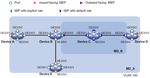
As shown in Figure 4:
· The network comprises five devices and is divided into two MDs: MD_A (level 5) and MD_B (level 3). All ports belong to VLAN 100, and the MAs in the two MDs all serve VLAN 100.
· MD_A has three edge ports: GigabitEthernet 3/0/1 on Device A, GigabitEthernet 3/0/3 on Device D, and GigabitEthernet 3/0/4 on Device E, and they are all inward-facing MEPs. MD_B has two edge ports: GigabitEthernet 3/0/3 on Device B and GigabitEthernet 3/0/1 on Device D, and they are both outward-facing MEPs.
· In MD_A, Device B is designed to have MIPs when its port is configured with low level MEPs. Port GigabitEthernet 3/0/3 is configured with MEPs of MD_B, and the MIPs of MD_A can be configured on this port. You should configure the MIP generation rule of MD_A as explicit.
· The MIPs of MD_B are designed on Device C, and are configured on all ports. You should configure the MIP generation rule as default.
· Configure CC to monitor the connectivity among all the MEPs in MD_A and MD_B. Configure to use LB to locate link faults, and use the AIS function to suppress the error alarms reported.
· After the status information of the entire network is obtained, use LT, LM, one-way DM, two-way DM, and TST to detect link faults.
Configuration procedure
1. Configure a VLAN and assign ports to it.
On each device shown in Figure 4, create VLAN 100 and assign ports GigabitEthernet 3/0/1 through GigabitEthernet 3/0/4 to VLAN 100.
2. Enable CFD.
# Enable CFD on Device A.
<DeviceA> system-view
[DeviceA] cfd enable
Enable CFD on Device B through Device E using the same method.
3. Configure service instances.
# Create MD_A (level 5) on Device A, create MA_A, which serves VLAN 100, in MD_A, and create service instance 1 for MD_A and MA_A.
[DeviceA] cfd md MD_A level 5
[DeviceA] cfd ma MA_A md MD_A vlan 100
[DeviceA] cfd service-instance 1 md MD_A ma MA_A
Configure Device E as you configure Device A.
# Create MD_A (level 5) on Device B, create MA_A, which serves VLAN 100, in MD_A, and then create service instance 1 for MD_A and MA_A; in addition, create MD_B (level 3), create MA_B, which serves VLAN 100, in MD_B, and then create service instance 2 for MD_B and MA_B.
[DeviceB] cfd md MD_A level 5
[DeviceB] cfd ma MA_A md MD_A vlan 100
[DeviceB] cfd service-instance 1 md MD_A ma MA_A
[DeviceB] cfd md MD_B level 3
[DeviceB] cfd ma MA_B md MD_B vlan 100
[DeviceB] cfd service-instance 2 md MD_B ma MA_B
Configure Device D as you configure Device B.
# Create MD_B (level 3) on Device C, create MA_B, which serves VLAN 100, in MD_B, and then create service instance 2 for MD_B and MA_B;
[DeviceC] cfd md MD_B level 3
[DeviceC] cfd ma MA_B md MD_B vlan 100
[DeviceC] cfd service-instance 2 md MD_B ma MA_B
4. Configure MEPs.
# On Device A, configure a MEP list in service instance 1; create and enable inward-facing MEP 1001 in service instance 1 on GigabitEthernet 3/0/1.
[DeviceA] cfd meplist 1001 4002 5001 service-instance 1
[DeviceA] interface GigabitEthernet3/0/1
[DeviceA-GigabitEthernet3/0/1] cfd mep 1001 service-instance 1 inbound
[DeviceA-GigabitEthernet3/0/1] cfd mep service-instance 1 mep 1001 enable
[DeviceA-GigabitEthernet3/0/1] quit
# On Device B, configure a MEP list in service instances 1 and 2 respectively; create and enable outward-facing MEP 2001 in service instance 2 on GigabitEthernet 3/0/3.
[DeviceB] cfd meplist 1001 4002 5001 service-instance 1
[DeviceB] cfd meplist 2001 4001 service-instance 2
[DeviceB] interface GigabitEthernet3/0/3
[DeviceB-GigabitEthernet3/0/3] cfd mep 2001 service-instance 2 outbound
[DeviceB-GigabitEthernet3/0/3] cfd mep service-instance 2 mep 2001 enable
[DeviceB-GigabitEthernet3/0/3] quit
# On Device D, configure a MEP list in service instances 1 and 2 respectively, create and enable outward-facing MEP 4001 in service instance 2 on GigabitEthernet 3/0/1, and then create and enable inward-facing MEP 4002 in service instance 1 on GigabitEthernet 3/0/3.
[DeviceD] cfd meplist 1001 4002 5001 service-instance 1
[DeviceD] cfd meplist 2001 4001 service-instance 2
[DeviceD] interface GigabitEthernet3/0/1
[DeviceD-GigabitEthernet3/0/1] cfd mep 4001 service-instance 2 outbound
[DeviceD-GigabitEthernet3/0/1] cfd mep service-instance 2 mep 4001 enable
[DeviceD-GigabitEthernet3/0/1] quit
[DeviceD] interface GigabitEthernet3/0/3
[DeviceD-GigabitEthernet3/0/3] cfd mep 4002 service-instance 1 inbound
[DeviceD-GigabitEthernet3/0/3] cfd mep service-instance 1 mep 4002 enable
[DeviceD-GigabitEthernet3/0/3] quit
# On Device E, configure a MEP list in service instance 1; create and enable inward-facing MEP 5001 in service instance 1 on GigabitEthernet 3/0/4.
[DeviceE] cfd meplist 1001 4002 5001 service-instance 1
[DeviceE] interface GigabitEthernet3/0/4
[DeviceE-GigabitEthernet3/0/4] cfd mep 5001 service-instance 1 inbound
[DeviceE-GigabitEthernet3/0/4] cfd mep service-instance 1 mep 5001 enable
[DeviceE-GigabitEthernet3/0/4] quit
5. Configure MIP generation rules.
# Configure the MIP generation rule in service instance 1 on Device B as explicit.
[DeviceB] cfd mip-rule explicit service-instance 1
# Configure the MIP generation rule in service instance 2 on Device C as default.
[DeviceC] cfd mip-rule default service-instance 2
6. Configure CC.
# On Device A, enable the sending of CCM frames for MEP 1001 in service instance 1 on GigabitEthernet 3/0/1.
[DeviceA] interface GigabitEthernet3/0/1
[DeviceA-GigabitEthernet3/0/1] cfd cc service-instance 1 mep 1001 enable
[DeviceA-GigabitEthernet3/0/1] quit
# On Device B, enable the sending of CCM frames for MEP 2001 in service instance 2 on GigabitEthernet 3/0/3.
[DeviceB] interface GigabitEthernet3/0/3
[DeviceB-GigabitEthernet3/0/3] cfd cc service-instance 2 mep 2001 enable
[DeviceB-GigabitEthernet3/0/3] quit
# On Device D, enable the sending of CCM frames for MEP 4001 in service instance 2 on GigabitEthernet 3/0/1, and enable the sending of CCM frames for MEP 4002 in service instance 1 on GigabitEthernet 3/0/3.
[DeviceD] interface GigabitEthernet3/0/1
[DeviceD-GigabitEthernet3/0/1] cfd cc service-instance 2 mep 4001 enable
[DeviceD-GigabitEthernet3/0/1] quit
[DeviceD] interface GigabitEthernet3/0/3
[DeviceD-GigabitEthernet3/0/3] cfd cc service-instance 1 mep 4002 enable
[DeviceD-GigabitEthernet3/0/3] quit
# On Device E, enable the sending of CCM frames for MEP 5001 in service instance 1 on GigabitEthernet 3/0/4.
[DeviceE] interface GigabitEthernet3/0/4
[DeviceE-GigabitEthernet3/0/4] cfd cc service-instance 1 mep 5001 enable
[DeviceE-GigabitEthernet3/0/4] quit
7. Configure AIS.
# Enable AIS on Device B, and configure the AIS frame transmission level as 2 and AIS frame transmission interval as 1 second in service instance 2.
[DeviceB] cfd ais enable
[DeviceB] cfd ais level 5 service-instance 2
[DeviceB] cfd ais period 1 service-instance 2
Verifying the configuration
1. Verify the LB function.
When the CC function detects a link fault, use the LB function to locate the fault.
# Enable LB on Device A to check the status of the link between MEP 1001 and MEP 5001 in service instance 1.
[DeviceA] cfd loopback service-instance 1 mep 1001 target-mep 5001
Loopback to 0010-FC00-6512 with the sequence number start from 1001-43404:
Reply from 0010-FC00-6512: sequence number=1001-43404 time=5ms
Reply from 0010-FC00-6512: sequence number=1001-43405 time=5ms
Reply from 0010-FC00-6512: sequence number=1001-43406 time=5ms
Reply from 0010-FC00-6512: sequence number=1001-43407 time=5ms
Reply from 0010-FC00-6512: sequence number=1001-43408 time=5ms
Send:5 Received:5 Lost:0
After the whole network status is obtained with the CC function, use the LT function to identify the paths between source and target MEPs or locate faults.
2. Verify the LT function.
# Identify the path between MEP 1001 and MEP 5001 in service instance 1 on Device A.
[DeviceA] cfd linktrace service-instance 1 mep 1001 target-mep 5001
Linktrace to MEP 5001 with the sequence number 1001-43462
MAC Address TTL Last MAC Relay Action
0010-FC00-6512 63 0010-FC00-6511 Hit
After the CC function obtains the status information of the entire network, use the TST function to test the bit errors of a link. For example:
# Test the bit errors on the link from MEP 1001 to MEP 4002 in service instance 1 on Device A.
[DeviceA] cfd tst service-instance 1 mep 1001 target-mep 4002
Info: TST process is done. Please check the result on the remote device.
# Display the TST result on MEP 4002 in service instance 1 on Device D.
[DeviceD] display cfd tst service-instance 1 mep 4002
Service instance: 1
MEP ID: 4002
Send TST total number: 0
Received TST total number: 5
Received from 0010-FC00-6510, sequence number 1: Bit True
Received from 0010-FC00-6510, sequence number 2: Bit True
Received from 0010-FC00-6510, sequence number 3: Bit True
Received from 0010-FC00-6510, sequence number 4: Bit True
Received from 0010-FC00-6510, sequence number 5: Bit True