- Table of Contents
-
- 07-Layer 3 - IP Routing Configuration Guide
- 00-Preface
- 01-IP Routing Basics
- 02-Static Routing Configuration
- 03-RIP Configuration
- 04-OSPF Configuration
- 05-IS-IS Configuration
- 06-BGP Configuration
- 07-Policy-Based Routing Configuration
- 08-Guard Route Configuration
- 09-IPv6 Static Routing Configuration
- 10-RIPng Configuration
- 11-OSPFv3 Configuration
- 12-IPv6 IS-IS Configuration
- 13-IPv6 BGP Configuration
- 14-IPv6 Policy-Based Routing Configuration
- 15-Routing Policy Configuration
- 16-Tunnel End Packets Policy Routing Configuration
- Related Documents
-
| Title | Size | Download |
|---|---|---|
| 02-Static Routing Configuration | 219 KB |
Contents
Configuring BFD for static routes
Displaying and maintaining static routes
Static route configuration examples
Basic static route configuration example
BFD for static routes configuration example (direct next hop)
BFD for static routes configuration example (indirect next hop)
Static route FRR configuration example
Introduction to default routes
Introduction to static routes
Static routes are manually configured. If a network’s topology is simple, you only need to configure static routes for the network to work properly.
Static routes cannot adapt to network topology changes. If a fault or a topological change occurs in the network, the network administrator must modify the static routes manually.
Configuring a static route
Configuration prerequisites
Before you configure a static route, complete the following tasks:
· Configure the physical parameters for related interfaces.
· Configure the link-layer attributes for related interfaces.
· Configure the IP addresses for related interfaces.
Configuration procedure
To configure a static route:
|
Step |
Command |
Remarks |
|
1. Enter system view. |
system-view |
N/A |
|
2. Configure a static route. |
·
Approach 1: ·
Approach 2: |
Use either approach. By default, no static route is configured. |
|
3. Configure the default preference for static routes. |
ip route-static default-preference default-preference-value |
Optional. 60 by default. |
|
4. Remove all static routes. |
delete [ vpn-instance vpn-instance-name ] static-routes all |
Optional. |
|
|
NOTE: · If you specify the next hop address of a static route and configure it as the IP address of a local interface, the static route does not take effect. · Associating track with static routing helps you determine the validity of static routes by monitoring the reachability of the next hops. For more information about track, see High Availability Configuration Guide. · Use the undo ip route-static command to delete one static route; use the delete static-routes all command to delete all static routes, including the default route. |
Configuring BFD for static routes
Bidirectional forwarding detection (BFD) provides a general-purpose, standard, medium-, and protocol-independent fast failure detection mechanism. It can uniformly and quickly detect the failures of the bidirectional forwarding paths between two routers for protocols, such as routing protocols and Multiprotocol Label Switching (MPLS). For more information about BFD, see High Availability Configuration Guide.
BFD control packet mode
To use BFD control packets for bidirectional detection between two devices, enable BFD control packet mode for each device’s static route destined to the peer.
To configure a static route and enable BFD control packet mode for it, specify an outbound interface and a direct next hop, or specify an indirect next hop and a specific BFD packet source address for the static route.
To configure a static route with BFD control packet mode enabled (direct next hop):
|
Step |
Command |
Remarks |
|
1. Enter system view. |
system-view |
N/A |
|
2. Configure a static route and enable BFD control packet mode for it. |
·
Approach 1: ·
Approach 2: |
Use either approach. |
To configure a static route with BFD control packet mode enabled (indirect next hop):
|
Step |
Command |
Remarks |
|
1. Enter system view. |
system-view |
N/A |
|
2. Configure a static route and enable BFD control packet mode for it. |
·
Approach 1: ·
Approach 2: |
Use either approach. |
BFD echo packet mode
With BFD echo packet mode enabled for a static route, the local switch sends BFD echo packets to the peer, which loops it back to test the link.
To configure BFD echo packet mode for static routes:
|
Step |
Command |
Remarks |
|
1. Enter system view. |
system-view |
N/A |
|
2. Configure the source address of echo packets. |
bfd echo-source-ip ip-address |
Not configured by default. For more information about this command, see High Availability Command Reference. |
|
3. Enable BFD echo packet mode for static routes. |
·
Approach 1: ·
Approach 2: |
Use either approach. |
|
|
CAUTION: · If route flaps occur, enabling BFD could worsen them. · Do not use BFD for a static route with the outbound interface in spoofing state. · BFD can be used for static routes with direct next hops rather than indirect next hops. · A BFD session is established at only one end when the echo mode is used. · For the echo and control mode, the switch currently does not support BFD detection on tunnel interfaces. |
Configuring static route FRR
When a link or a router fails, the packets on the path are discarded, and a routing loop occurs. To avoid such problems, you can enable static route fast reroute (FRR).
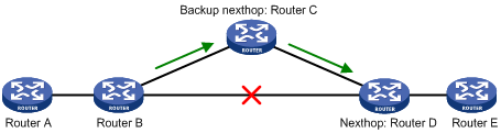
As shown in Figure 1, upon a link failure, FRR designates a backup next hop by using a routing policy for routes matching the specified criteria. Packets are directed to the backup next hop to avoid traffic interruption.
Configuration prerequisites
Create a routing policy to be referenced by FRR and use the apply fast-reroute backup-interface command to specify a backup next hop in a routing policy. For more information about the command and routing policy configurations, see the chapter “Configuring routing policy.”
Configuration procedure
To configure static route FRR:
|
Step |
Command |
Remarks |
|
1. Enter system view. |
system-view |
N/A |
|
1. Configure the source address of BFD echo packets. |
bfd echo-source-ip ip-address |
Not configured by default. For more information about this command, see High Availability Command Reference. |
|
2. Configure static route FRR. |
ip route-static [ vpn-instance vpn-instance-name ] fast-reroute route-policy route-policy-name |
Not configured by default. |
|
|
NOTE: · Static route FRR takes effect only for static routes that have both the outbound interface and next hop specified. · Do not use static route FRR and BFD (for static route) at the same time. |
Displaying and maintaining static routes
|
Task |
Command |
Remarks |
|
View information of static routes. |
display ip routing-table protocol static [ inactive | verbose ] [ | { begin | exclude | include } regular-expression ] |
Available in any view |
|
Delete all static routes. |
delete [ vpn-instance vpn-instance-name ] static-routes all |
Available in system view |
|
|
NOTE: For more information about this command, see Layer 3—IP Routing Command Reference. |
Static route configuration examples
|
|
NOTE: By default, Ethernet, VLAN, and aggregate interfaces are down. Before configuring these interfaces, bring them up by using the undo shutdown command. |
Basic static route configuration example
Network requirements
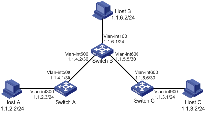
Configure static routes in Figure 2 to achieve interconnections between any two hosts.
Configuration procedure
1. Configure IP addresses for interfaces. (Details not shown)
2. Configure static routes:
# Configure a default route on Switch A.
<SwitchA> system-view
[SwitchA] ip route-static 0.0.0.0 0.0.0.0 1.1.4.2
# Configure two static routes on Switch B.
<SwitchB> system-view
[SwitchB] ip route-static 1.1.2.0 255.255.255.0 1.1.4.1
[SwitchB] ip route-static 1.1.3.0 255.255.255.0 1.1.5.6
# Configure a default route on Switch C.
<SwitchC> system-view
[SwitchC] ip route-static 0.0.0.0 0.0.0.0 1.1.5.5
3. Configure the hosts:
The default gateways for the three hosts A, B, and C are 1.1.2.3, 1.1.6.1, and 1.1.3.1 respectively. (Details not shown)
4. Verify the configuration:
# Display the IP routing table of Switch A.
[SwitchA] display ip routing-table
Routing Tables: Public
Destinations : 7 Routes : 7
Destination/Mask Proto Pre Cost NextHop Interface
0.0.0.0/0 Static 60 0 1.1.4.2 Vlan500
1.1.2.0/24 Direct 0 0 1.1.2.3 Vlan300
1.1.2.3/32 Direct 0 0 127.0.0.1 InLoop0
1.1.4.0/30 Direct 0 0 1.1.4.1 Vlan500
1.1.4.1/32 Direct 0 0 127.0.0.1 InLoop0
127.0.0.0/8 Direct 0 0 127.0.0.1 InLoop0
127.0.0.1/32 Direct 0 0 127.0.0.1 InLoop0
# Display the IP routing table of Switch B.
[SwitchB] display ip routing-table
Routing Tables: Public
Destinations : 10 Routes : 10
Destination/Mask Proto Pre Cost NextHop Interface
1.1.2.0/24 Static 60 0 1.1.4.1 Vlan500
1.1.3.0/24 Static 60 0 1.1.5.6 Vlan600
1.1.4.0/30 Direct 0 0 1.1.4.2 Vlan500
1.1.4.2/32 Direct 0 0 127.0.0.1 InLoop0
1.1.5.0/30 Direct 0 0 1.1.5.5 Vlan600
1.1.5.5/32 Direct 0 0 127.0.0.1 InLoop0
127.0.0.0/8 Direct 0 0 127.0.0.1 InLoop0
127.0.0.1/32 Direct 0 0 127.0.0.1 InLoop0
1.1.6.0/24 Direct 0 0 1.1.6.1 Vlan100
1.1.6.1/32 Direct 0 0 127.0.0.1 InLoop0
# Use the ping command on Host B to check reachability to Host A (Windows XP runs on the two hosts).
C:\Documents and Settings\Administrator>ping 1.1.2.2
Pinging 1.1.2.2 with 32 bytes of data:
Reply from 1.1.2.2: bytes=32 time=1ms TTL=126
Reply from 1.1.2.2: bytes=32 time=1ms TTL=126
Reply from 1.1.2.2: bytes=32 time=1ms TTL=126
Reply from 1.1.2.2: bytes=32 time=1ms TTL=126
Ping statistics for 1.1.2.2:
Packets: Sent = 4, Received = 4, Lost = 0 (0% loss),
Approximate round trip times in milli-seconds:
Minimum = 1ms, Maximum = 1ms, Average = 1ms
# Use the tracert command on Host B to check reachability to Host A.
C:\Documents and Settings\Administrator>tracert 1.1.2.2
Tracing route to 1.1.2.2 over a maximum of 30 hops
1 <1 ms <1 ms <1 ms 1.1.6.1
2 <1 ms <1 ms <1 ms 1.1.4.1
3 1 ms <1 ms <1 ms 1.1.2.2
Trace complete.
BFD for static routes configuration example (direct next hop)
Network requirements
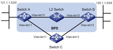
In Figure 3, configure a static route to subnet 120.1.1.0/24 on Switch A and configure a static route to subnet 121.1.1.0/24 on Switch B. Enable BFD for both routes so that when the link between Switch A and Switch B through the Layer 2 switch fails, BFD can detect the failure immediately and Switch A and Switch B can communicate through Switch C.
|
Device |
Interface |
IP address |
Device |
Interface |
IP address |
|
Switch A |
Vlan-int10 |
12.1.1.1/24 |
Switch B |
Vlan-int10 |
12.1.1.2/24 |
|
|
Vlan-int11 |
10.1.1.102/24 |
|
Vlan-int13 |
13.1.1.1/24 |
|
Switch C |
Vlan-int11 |
10.1.1.100/24 |
|
|
|
|
|
Vlan-int13 |
13.1.1.2/24 |
|
|
|
Configuration procedure
1. Configure IP addresses for the interfaces. (Details not shown)
2. Configure static routes and BFD:
# Configure static routes on Switch A and enable BFD control packet mode for the static route through the Layer 2 switch.
<SwitchA> system-view
[SwitchA] interface vlan-interface10
[SwitchA-vlan-interface10] bfd min-transmit-interval 500
[SwitchA-vlan-interface10] bfd min-receive-interval 500
[SwitchA-vlan-interface10] bfd detect-multiplier 9
[SwitchA-vlan-interface10] quit
[SwitchA] ip route-static 120.1.1.0 24 vlan-interface 10 12.1.1.2 bfd control-packet
[SwitchA] ip route-static 120.1.1.0 24 vlan-interface 11 10.1.1.100 preference 65
[SwitchA] quit
# Configure static routes on Switch B and enable BFD control packet mode for the static route through the Layer 2 switch.
<SwitchB> system-view
[SwitchB] interface vlan-interface10
[SwitchB-vlan-interface10] bfd min-transmit-interval 500
[SwitchB-vlan-interface10] bfd min-receive-interval 500
[SwitchB-vlan-interface10] bfd detect-multiplier 9
[SwitchB-vlan-interface10]] quit
[SwitchB] ip route-static 121.1.1.0 24 vlan-interface 10 12.1.1.1 bfd control-packet
[SwitchB] ip route-static 121.1.1.0 24 vlan-interface 13 13.1.1.2 preference 65
[SwitchB] quit
3. Verify the configuration:
The following operations are performed on Switch A. The operations on Switch B are similar.
# Display the BFD session information.
<SwitchA> display bfd session
Total Session Num: 1 Init Mode: Active
Session Working Under Ctrl Mode:
LD/RD SourceAddr DestAddr State Holdtime Interface
4/7 12.1.1.1 12.1.1.2 Up 2000ms Vlan10
# Display the static route information. The static route to Switch B through the Layer 2 switch is displayed in the output.
<SwitchA> display ip routing-table protocol static
Public Routing Table : Static
Summary Count : 2
Static Routing table Status : <Active>
Summary Count : 1
Destination/Mask Proto Pre Cost NextHop Interface
120.1.1.0/24 Static 60 0 12.1.1.2 Vlan10
Direct Routing table Status : <Inactive>
Summary Count : 1
Destination/Mask Proto Pre Cost NextHop Interface
120.1.1.0/24 Static 65 0 10.1.1.100 Vlan11
# Enable BFD debugging. When the link between Switch A and Layer 2 switch fails, Switch A can detect the failure.
<SwitchA> debugging bfd event
<SwitchA> debugging bfd scm
<SwitchA> terminal debugging
%Jul 27 10:18:18:672 2007 SwitchA BFD/4/LOG:Sess[12.1.1.1/12.1.1.2, Vlan10,Ctrl], Sta: UP->DOWN, Diag: 1
*Jul 27 10:18:18:672 2007 SwitchA BFD/7/EVENT:Send sess-down Msg, [Src:12.1.1.1,Dst:12.1.1.2, Vlan10,Ctrl], instance:0, protocol:STATIC
*Jul 27 10:18:19:172 2007 SwitchA BFD/7/EVENT:Receive Delete-sess, [Src:12.1.1.1,Dst:12.1.1.2, Vlan10,Ctrl], Direct, Instance:0x0, Proto:STATIC
*Jul 27 10:18:19:172 2007 SwitchA BFD/7/EVENT:Notify driver to stop receiving bf
# Display the static route information on Switch A again. Switch A communicates with Switch B over the static route passing Switch C now.
<SwitchA> display ip routing-table protocol static
Public Routing Table : Static
Summary Count : 2
Static Routing table Status : <Active>
Summary Count : 1
Destination/Mask Proto Pre Cost NextHop Interface
120.1.1.0/24 Static 65 0 10.1.1.100 Vlan11
Static Routing table Status : <Inactive>
Summary Count : 1
Destination/Mask Proto Pre Cost NextHop Interface
120.1.1.0/24 Static 60 0 12.1.1.2 Vlan10
BFD for static routes configuration example (indirect next hop)
Network requirements
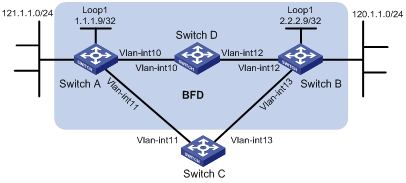
In Figure 4, Switch A has a route to interface Loopback1 (2.2.2.9/32) on Switch B, with outbound interface VLAN-interface 10. Switch B has a route to interface Loopback1 (1.1.1.9/32) on Switch A, with outbound interface VLAN-interface 12. Switch D has a route to 1.1.1.9/32, with outbound interface VLAN-interface 10, and a route to 2.2.2.9/32, with outbound interface VLAN-interface 12.
Configure a static route to subnet 120.1.1.0/24 on Switch A and configure a static route to subnet 121.1.1.0/24 on Switch B. Enable BFD for both routes so that when the link between Switch A and Switch B through Switch D fails, BFD can detect the failure immediately and Switch A and Switch B can communicate through Switch C.
|
Device |
Interface |
IP address |
Device |
Interface |
IP address |
|
Switch A |
Vlan-int10 |
12.1.1.1/24 |
Switch B |
Vlan-int12 |
11.1.1.1/24 |
|
|
Vlan-int11 |
10.1.1.102/24 |
|
Vlan-int13 |
13.1.1.1/24 |
|
|
Loop1 |
1.1.1.9/32 |
|
Loop1 |
2.2.2.9/32 |
|
Switch C |
Vlan-int11 |
10.1.1.100/24 |
Switch D |
Vlan-int10 |
12.1.1.2/24 |
|
|
Vlan-int13 |
13.1.1.2/24 |
|
Vlan-int12 |
11.1.1.2/24 |
Configuration procedure
1. Configure IP addresses for the interfaces. (Details not shown)
2. Configure static routes and BFD:
# Configure static routes on Switch A and enable BFD control packet mode for the static route through Switch D.
<SwitchA> system-view
[SwitchA] interface loopback 1
[SwitchA-LoopBack1] bfd min-transmit-interval 500
[SwitchA-LoopBack1] bfd min-receive-interval 500
[SwitchA-LoopBack1] bfd detect-multiplier 9
[SwitchA-LoopBack1] quit
[SwitchA] ip route-static 120.1.1.0 24 2.2.2.9 bfd control-packet bfd-source 1.1.1.9
[SwitchA] ip route-static 120.1.1.0 24 vlan-interface 11 10.1.1.100 preference 65
[SwitchA] quit
# Configure static routes on Switch B and enable BFD control packet mode for the static route through Switch D.
<SwitchB> system-view
[SwitchB] interface loopback 1
[SwitchB-LoopBack1] bfd min-transmit-interval 500
[SwitchB-LoopBack1] bfd min-receive-interval 500
[SwitchB-LoopBack1] bfd detect-multiplier 9
[SwitchB-LoopBack1] quit
[SwitchB] ip route-static 121.1.1.0 24 1.1.1.9 bfd control-packet bfd-source 2.2.2.9
[SwitchB] ip route-static 121.1.1.0 24 vlan-interface 13 13.1.1.2 preference 65
[SwitchB] quit
3. Verify the configuration:
The following operations are performed on Switch A. The operations on Switch B are similar and are not shown.
# Display the BFD session information.
<SwitchA> display bfd session
Total session number: 1 Up session number: 0 Init mode: Active
IPv4 session working under Ctrl mode:
LD/RD SourceAddr DestAddr State Holdtime Interface
4/7 1.1.1.9 2.2.2.9 Up 2000ms Loop1
# Display the static route information. The static route to Switch B through Switch D is displayed in the output.
<SwitchA> display ip routing-table protocol static
Public Routing Table : Static
Summary Count : 2
Static Routing table Status : <Active>
Summary Count : 1
Destination/Mask Proto Pre Cost NextHop Interface
120.1.1.0/24 Static 60 0 2.2.2.9 Vlan10
Static Routing table Status : <Inactive>
Summary Count : 1
Destination/Mask Proto Pre Cost NextHop Interface
120.1.1.0/24 Static 65 0 10.1.1.100 Vlan11
# Enable BFD debugging. When the link between Switch A and Switch D fails, Switch A can detect the failure.
<SwitchA> debugging bfd event
<SwitchA> debugging bfd scm
<SwitchA> terminal debugging
%Oct 10 10:18:18:672 2010 SwitchA BFD/4/LOG:Sess[1.1.1.9/2.2.2.9, Loop1,Ctrl], Sta: UP->DOWN, Diag: 1
* Oct 10 10:18:18:672 2010 SwitchA BFD/7/EVENT:Send sess-down Msg, [Src:1.1.1.9,Dst:2.2.2.9, Loop1,Ctrl], instance:0, protocol:STATIC
# Display the static route information on Switch A again. Switch A communicates with Switch B over the static route passing Switch C now.
<SwitchA> display ip routing-table protocol static
Public Routing Table : Static
Summary Count : 2
Static Routing table Status : <Active>
Summary Count : 1
Destination/Mask Proto Pre Cost NextHop Interface
120.1.1.0/24 Static 65 0 10.1.1.100 Vlan11
Static Routing table Status : <Inactive>
Summary Count : 1
Destination/Mask Proto Pre Cost NextHop Interface
120.1.1.0/24 Static 60 0 2.2.2.9
Static route FRR configuration example
Network requirements
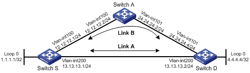
Figure 5 shows that Switch S, Switch A, and Switch D are interconnected through static routes. Configure static route FRR so that when Link A between Switch S and Switch D fails, traffic can be switched to Link B immediately.
Configuration procedure
1. Configure IP addresses for the interfaces on each switch. (Details not shown)
2. Configure static routes:
Configure static routes on Switch S, Switch A, and Switch D so that Switch S can reach Loopback 0 on Switch D and Switch D can reach Loopback 0 on Switch S.
# Configure a static route on Switch S.
<SwitchS> system-view
[SwitchS] ip route-static 4.4.4.4 32 vlan-interface 200 13.13.13.2
[SwitchS] ip route-static 4.4.4.4 32 vlan-interface 100 12.12.12.2 preference 65
# Configure a static route on Switch D.
<SwitchD> system-view
[SwitchD] ip route-static 1.1.1.1 32 vlan-interface 200 13.13.13.1
[SwitchD] ip route-static 1.1.1.1 32 vlan-interface 101 24.24.24.2 preference 65
# Configure a static route on Switch A.
<SwitchA> system-view
[SwitchA] ip route-static 4.4.4.4 32 vlan-interface 101 24.24.24.4
[SwitchA] ip route-static 1.1.1.1 32 vlan-interface 100 12.12.12.1
3. Configure static route FRR:
# Configure Switch S.
[SwitchS] bfd echo-source-ip 1.1.1.1
[SwitchS] ip ip-prefix abc index 10 permit 4.4.4.4 32
[SwitchS] route-policy frr permit node 10
[SwitchS-route-policy] if-match ip-prefix abc
[SwitchS-route-policy] apply fast-reroute backup-interface vlan-interface 100 backup-nexthop 12.12.12.2
[SwitchS-route-policy] quit
[SwitchS] ip route-static fast-reroute route-policy frr
# Configure Switch D.
[SwitchD] bfd echo-source-ip 4.4.4.4
[SwitchD] ip ip-prefix abc index 10 permit 1.1.1.1 32
[SwitchD] route-policy frr permit node 10
[SwitchD-route-policy] if-match ip-prefix abc
[SwitchD-route-policy] apply fast-reroute backup-interface vlan-interface 101 backup-nexthop 24.24.24.2
[SwitchD-route-policy] quit
[SwitchD] ip route-static fast-reroute route-policy frr
4. Verify the configuration:
# Display route 4.4.4.4/32 on Switch S to view the backup next hop information.
[SwitchS] display ip routing-table 4.4.4.4 verbose
Routing Table : Public
Summary Count : 2
Destination: 4.4.4.4/32
Protocol: Static Process ID: 0
Preference: 60 Cost: 0
IpPrecedence: QosLcID:
NextHop: 13.13.13.2 Interface: vlan 200
BkNextHop: 12.12.12.2 BkInterface: vlan 100
RelyNextHop: 0.0.0.0 Neighbor : 0.0.0.0
Tunnel ID: 0x0 Label: NULL
BKTunnel ID: 0x0 BKLabel: NULL
State: Active Adv Age: 00h01m27s
Tag: 0
Destination: 4.4.4.4/32
Protocol: Static Process ID: 0
Preference: 100 Cost: 0
NextHop: 13.13.13.2 Interface: vlan 200
BkNextHop: 0.0.0.0 BkInterface:
RelyNextHop: 0.0.0.0 Neighbor : 0.0.0.0
Tunnel ID: 0x0 Label: NULL
BKTunnel ID: 0x0 BKLabel: NULL
State: Active Adv Age: 00h01m27s
Tag: 0
# Display route 1.1.1.1/32 on Switch D to view the backup next hop information.
[SwitchD] display ip routing-table 1.1.1.1 verbose
Routing Table : Public
Summary Count : 2
Destination: 1.1.1.1/32
Protocol: Static Process ID: 0
Preference: 60 Cost: 0
IpPrecedence: QosLcID:
NextHop: 13.13.13.1 Interface: vlan 200
BkNextHop: 24.24.24.2 BkInterface: vlan 101
RelyNextHop: 0.0.0.0 Neighbor : 0.0.0.0
Tunnel ID: 0x0 Label: NULL
BKTunnel ID: 0x0 BKLabel: NULL
State: Active Adv Age: 00h01m27s
Tag: 0
Destination: 1.1.1.1/32
Protocol: Static Process ID: 0
Preference: 100 Cost: 0
NextHop: 13.13.13.1 Interface: vlan 200
BkNextHop: 0.0.0.0 BkInterface:
RelyNextHop: 0.0.0.0 Neighbor : 0.0.0.0
Tunnel ID: 0x0 Label: NULL
BKTunnel ID: 0x0 BKLabel: NULL
State: Active Adv Age: 00h01m27s
Tag: 0
Introduction to default routes
A default route is used to forward packets that match no entry in the routing table.
Without a default route, a packet that does not match any routing entries is discarded and an Internet Control Message Protocol (ICMP) destination-unreachable packet is sent to the source.
Default route can be configured in either of the following ways:
· The network administrator can configure a default route with both destination and mask being 0.0.0.0. For more information, see the chapter “Configuring static routing.”
· Some dynamic routing protocols, such as Open Shortest Path First (OSPF), Routing Information Protocol (RIP), and Intermediate System-to-Intermediate System (IS-IS), can generate a default route. For example, an upstream router running OSPF can generate a default route and advertise it to other routers, which install the default route with the next hop being the upstream router. For more information, see configuration guides of relevant routing protocols.