- Table of Contents
-
- 07-Layer 3 - IP Routing Configuration Guide
- 00-Preface
- 01-IP Routing Basics
- 02-Static Routing Configuration
- 03-RIP Configuration
- 04-OSPF Configuration
- 05-IS-IS Configuration
- 06-BGP Configuration
- 07-Policy-Based Routing Configuration
- 08-Guard Route Configuration
- 09-IPv6 Static Routing Configuration
- 10-RIPng Configuration
- 11-OSPFv3 Configuration
- 12-IPv6 IS-IS Configuration
- 13-IPv6 BGP Configuration
- 14-IPv6 Policy-Based Routing Configuration
- 15-Routing Policy Configuration
- 16-Tunnel End Packets Policy Routing Configuration
- Related Documents
-
| Title | Size | Download |
|---|---|---|
| 14-IPv6 Policy-Based Routing Configuration | 136.27 KB |
Contents
Configuring IPv6 policy-based routing
Introduction to IPv6 policy-based routing
Configuring IPv6 interface PBR
Displaying and maintaining IPv6 PBR configuration
IPv6 PBR configuration examples
Configuring IPv6 local PBR based on packet type
Configuring IPv6 interface PBR based on packet type
|
|
NOTE: The switch operates in IRF or standalone (the default) mode. For information about the IRF mode, see IRF Configuration Guide. |
Introduction to IPv6 policy-based routing
IPv6 policy-based routing is used to route IPv6 unicasts based on a policy.
Policy-based routing
Policy-based routing (PBR) is a routing mechanism based on the user-defined policies. Different from the traditional destination-based routing mechanism, PBR enables you to implement policies (based on the source address, address length, and other criteria) that make packets flexibly take different routes. You can specify the VPN instance, the packet priority, the outgoing interface, next hop, default outgoing interface, default next hop, and other parameters to guide forwarding of the packets matching an ACL or with a specific length.
According to the objects to which the PBR applies, PBR involves local PBR and interface PBR:
· Local PBR applies to locally generated packets only, such as the ICMP packets generated by using the ping command.
· Interface PBR applies to packets forwarded through an interface only.
In most cases, interface PBR is implemented to meet the forwarding and security requirements.
In general, PBR takes precedence over destination-based routing. PBR is applied when packets match the specified criteria. Otherwise, destination-based routing is applied.
IPv6 PBR
An IPv6 policy is used to route IPv6 packets.
An IPv6 policy can consist of one or multiple nodes.
Node
A node is identified by a node number. The node with the smallest node number has the highest priority.
A policy consists of if-match and apply clauses. An if-match clause defines specifies a match criterion on a node, and an apply clause specifies action to be taken on packets.
The action to be taken on matched packets depends on the match mode, which can be permit or deny
Table 1 Relationship between the match mode and the clauses
|
If a packet… |
Then… |
|
|
In permit mode |
In deny mode |
|
|
Matches all the if-match clauses on the policy node |
The apply clause is executed, and the packet will not go to the next policy node for a match. |
The apply clause is not executed, the packets will not go to the next policy node for a match, and will be forwarded according to the routing table. |
|
Fails to match an if-match clause on the policy node |
The apply clause is not executed, and the packet will go to the next policy node for a match. |
The apply clause is not executed, and the packet will go to the next policy node for a match. |
|
|
NOTE: · If a policy has a node with no if-match clause configured, all packets can pass the policy node. However, an action is taken according to the match mode, and the packets will not go to the next policy node for a match. · If a policy has a node with the permit match mode but no apply clause configured, all packets matching all the if-match clauses can pass the policy node, and no action is taken; the packets will not go to the next policy node for a match, and will be forwarded according to the routing table. · If a policy has a node with no if-match or apply clauses configured, all packets can pass the policy node, and no action is taken; the packets will not go to the next policy node for a match, and will be forwarded according to the routing table. |
The nodes of a policy are in an OR relationship. If a packet matches a node, it passes the policy; if the packet does not match any node of the policy, it fails to pass the policy and is forwarded according to the routing table.
if-match clause
The following type of if-match clause is available: if-match acl6.
You can specify only one if-match clause in a policy node.
apply clause
IPv6 PBR supports the following types of apply clauses in Table 2.
Table 2 Priorities of the apply clauses in a policy node
|
Clause |
Meaning |
Priority |
|
apply ipv6-precedence |
Sets an IP precedence |
If configured, this clause will always be executed. |
|
apply ipv6-address next-hop |
Sets the next hop |
This clause will be executed as long as the configured next hop is valid. |
Configuring IPv6 PBR
Configuring IPv6 policy
To define an IPv6 policy:
|
Step |
Command |
Remarks |
|
1. Enter system view. |
system-view |
N/A |
|
2. Create an IPv6 policy or IPv6 policy node and enter IPv6 PBR policy node view. |
ipv6 policy-based-route policy-name [ deny | permit ] node node-number |
Not created by default. |
|
3. Define an IPv6 ACL match criterion. |
if-match acl6 acl6-number |
Optional. |
|
4. Set a preference type or value for permitted IPv6 packets. |
apply ipv6-precedence { type | value } |
Optional. |
|
5. Set a next hop for permitted IPv6 packets. |
apply ipv6-address next-hop ipv6-address |
Optional. If you set two next hops for a policy, only the primary next hop takes effect. The backup next hop takes effect only when the primary next hop is invalid. |
|
|
NOTE: · You can specify up to two next hops for a policy (only one next hop can be specified in one command line). When neither next hop takes effect, packets are forwarded according to the routing table. · The rule you add to an ACL that has been used by a policy cannot take effect if hardware resources are insufficient or the policy does not support the rule. Such rules are marked as uncompleted in the output of the display acl { acl-number | all | name acl-name } slot slot-number command. To successfully apply the rule, you must delete the rule and reconfigure it when hardware resources are sufficient. For more information about the display acl command, see ACL and QoS Command Reference. · If an ACL match criterion is defined, packets are matched against the ACL rules, whereas the permit or deny action of the specified ACL is ignored. If the specified ACL does not exist, no packet is matched. |
Configuring IPv6 local PBR
Local PBR applies to locally generated packets only. Only one policy can be referenced for IPv6 local PBR.
To configure IPv6 local PBR:
|
Step |
Command |
Remarks |
|
1. Enter system view. |
system-view |
N/A |
|
2. Configure IPv6 local PBR. |
ipv6 local policy-based-route policy-name |
Not configured by default |
|
|
NOTE: · If the specified policy does not exist, the IPv6 local PBR configuration succeeds, but it takes effect only when the policy is created. · IPv6 local PBR supports only IP forwarding. |
Configuring IPv6 interface PBR
Interface PBR applies only to packets forwarded through an interface. Only one policy can be referenced by an interface for IPv6 interface PBR.
To configure IPv6 interface PBR:
|
Step |
Command |
Remarks |
|
1. Enter system view. |
system-view |
N/A |
|
2. Enter interface view. |
interface interface-type interface-number |
N/A |
|
3. Configure IPv6 interface PBR. |
ipv6 policy-based-route policy-name |
Not configured by default |
|
|
NOTE: · If the specified policy does not exist, the IPv6 interface PBR configuration succeeds, but it takes effect only when the policy is created. · To configure IPv6 interface PBR on an EC or EF card, for example, LSR1GP48LEC1 or LSR1GP48LEF1, you must configure the acl ipv6 enable command in system view first. For more information about the acl ipv6 enable command, see ACL and QoS Command Reference. For more information about EC and EF cards, see Fundamentals Configuration Guide. |
Displaying and maintaining IPv6 PBR configuration
|
Task |
Command |
Remarks |
|
Display the IPv6 PBR routing information. |
display ipv6 policy-based-route [ | { begin | exclude | include } regular-expression ] |
Available in any view |
|
Display the specified IPv6 PBR routing information (in standalone mode). |
display ipv6 policy-based-route setup { policy-name | interface interface-type interface-number [ slot slot-number ] | local [ slot slot-number ] } [ | { begin | exclude | include } regular-expression ] |
Available in any view |
|
Display the specified IPv6 PBR routing information (in IRF mode). |
display ipv6 policy-based-route setup { policy-name | interface interface-type interface-number [ chassis chassis-number slot slot-number ] | local [ chassis chassis-number slot slot-number ] } [ | { begin | exclude | include } regular-expression ] |
Available in any view |
|
Display IPv6 PBR statistics (in standalone mode). |
display ipv6 policy-based-route statistics { interface interface-type interface-number | local } [ slot slot-number ] [ | { begin | exclude | include } regular-expression ] |
Available in any view |
|
Display IPv6 PBR statistics (in IRF mode). |
display ipv6 policy-based-route statistics { interface interface-type interface-number | local } [ chassis chassis-number slot slot-number ] [ | { begin | exclude | include } regular-expression ] |
Available in any view |
|
Display IPv6 PBR policy information (in standalone mode). |
display ipv6 config policy-based-route [ policy-name [ slot slot-number ] ] [ | { begin | exclude | include } regular-expression ] |
Available in any view |
|
Display IPv6 PBR policy information (in IRF mode). |
display ipv6 config policy-based-route [ policy-name [ chassis chassis-number slot slot-number ] ] [ | { begin | exclude | include } regular-expression ] |
Available in any view |
|
Clear IPv6 PBR statistics. |
reset ipv6 policy-based-route statistics |
Available in user view |
|
|
NOTE: · If a policy has a node with no if-match or apply clause configured, all packets can pass the policy and will not go to the next policy node for a match. The statistics of IPv6 PBR will be changed. · If a policy node has if-match clauses but no apply clauses configured, packets will match against these if-match clauses. However, no apply clauses are applicable to the permitted packets, and the packets will not go to the next node for a match. The statistics of IPv6 PBR will be changed. · If a policy node has no if-match clause but apply clauses configured, all packets can pass the policy, and then are forwarded according to the apply clauses if the permit keyword is specified for the node, or are denied if the deny keyword is specified. The packets will not go to the next policy node for a match. The statistics of IPv6 PBR will be changed. · If the match mode of a policy node is deny, no apply clauses will be executed for packets satisfying all the if-match clauses, and the packets will not go to the next policy node for a match. They will be forwarded according to the routing table instead. Neither debugging information nor statistics for the deny match mode can be displayed. |
IPv6 PBR configuration examples
|
|
NOTE: By default, Ethernet, VLAN, and aggregate interfaces are down. Before configuring these interfaces, bring them up by using the undo shutdown command. |
Configuring IPv6 local PBR based on packet type
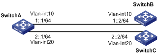
Network requirements
As shown in Figure 1, configure PBR on Switch A so that all TCP packets are forwarded through next hop 1::2, and other IPv6 packets are forwarded according to the routing table.
Switch A is directly connected to Switch B and Switch C, respectively. Switch B and Switch C are unreachable to each other.
Configuration procedure
1. Configure Switch A:
# Define ACL 3001 to match TCP packets.
<SwitchA> system-view
[SwitchA] ipv6
[SwitchA] acl ipv6 number 3001
[SwitchA-acl6-adv-3001] rule permit tcp
[SwitchA-acl6-adv-3001] quit
# Define Node 5 of policy aaa, so that TCP packets are forwarded to next hop 1::2. .
[SwitchA] ipv6 policy-based-route aaa permit node 5
[SwitchA-pbr6-aaa-5] if-match acl6 3001
[SwitchA-pbr6-aaa-5] apply ipv6-address next-hop 1::2
[SwitchA-pbr6-aaa-5] quit
# Apply policy aaa to Switch A.
[SwitchA] ipv6 local policy-based-route aaa
# Configure the IPv6 addresses of the VLAN interfaces.
[SwitchA] interface Vlan-interface 10
[SwitchA-Vlan-interface10] ip address 1::1 64
[SwitchA-Vlan-interface10] quit
[SwitchA] interface Vlan-interface 20
[SwitchA-Vlan-interface20] ip address 2::1 64
2. Configure Switch B:
# Configure the IPv6 address for VLAN-interface 10.
<SwitchB> system-view
[SwitchB] interface Vlan-interface 10
[SwitchB-Vlan-interface10] ip address 1::2 64
[SwitchB-Vlan-interface10] quit
3. Configure Switch C:
# Configure the IPv6 address for VLAN-interface 20.
<SwitchC> system-view
[SwitchC] interface Vlan-interface 20
[SwitchC-Vlan-interface20] ip address 2::2 64
[SwitchC-Vlan-interface20] quit
4. Verify the configuration:
# Telnet to Switch B (1::2/64) from Switch A. The operation succeeds.
<SwitchA> telnet ipv6 1::2
Trying 1::2 ...
Press CTRL+K to abort
Connected to 1::2 ...
******************************************************************************
* Copyright (c) 2004-2011 Hangzhou H3C Tech. Co., Ltd. All rights reserved. *
* Without the owner's prior written consent, *
* no decompiling or reverse-engineering shall be allowed. *
******************************************************************************
# Telnet to Switch C (2::2/64) from Switch A. The operation fails.
<SwitchA> telnet ipv6 2::2
Trying 2::2 ...
Press CTRL+K to abort
Can't connect to the remote host!
# Ping Switch C (2::2/64) from Switch A. The operation succeeds.
<SwitchA> ping ipv6 2::2
PING 2::2 : 56 data bytes, press CTRL_C to break
Reply from 2::2
bytes=56 Sequence=1 hop limit=64 time = 4 ms
Reply from 2::2
bytes=56 Sequence=2 hop limit=64 time = 2 ms
Reply from 2::2
bytes=56 Sequence=3 hop limit=64 time = 2 ms
Reply from 2::2
bytes=56 Sequence=4 hop limit=64 time = 2 ms
Reply from 2::2
bytes=56 Sequence=5 hop limit=64 time = 2 ms
--- 2::2 ping statistics ---
5 packet(s) transmitted
5 packet(s) received
0.00% packet loss
round-trip min/avg/max = 2/2/4 ms
Telnet uses TCP, and ping uses ICMP. The preceding results indicate that all TCP packets of Switch A are forwarded to next hop 1::2, and other packets are forwarded according to the routing table. The PBR configuration is effective.
Configuring IPv6 interface PBR based on packet type
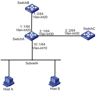
Network requirements
As shown in Figure 2, configure PBR on the VLAN-interface 10 of Switch A, so that TCP packets arriving on VLAN-interface 10 are forwarded through next hop 1::2/64 and other IPv6 packets are forwarded according to the routing table.
Switch A is directly connected to Switch B and Switch C. Switch B and Switch C are unreachable to each other.
Configuration procedure
|
|
NOTE: In this example, RIPng is configured to ensure the reachability among switches. |
1. Configure Switch A:
# Configure RIPng.
<SwitchA> system-view
[SwitchA] ipv6
[SwitchA] ripng 1
[SwitchA-ripng-1] quit
[SwitchA] interface Vlan-interface 20
[SwitchA-Vlan-interface20] ipv6 address 1::1 64
[SwitchA-Vlan-interface20] ripng 1 enable
[SwitchA-Vlan-interface20] quit
[SwitchA] interface Vlan-interface 30
[SwitchA-Vlan-interface30] ipv6 address 2::1 64
[SwitchA-Vlan-interface30] ripng 1 enable
[SwitchA-Vlan-interface30] quit
# Define ACL 3001 to match TCP packets.
<SwitchA> system-view
[SwitchA] ipv6
[SwitchA] acl ipv6 number 3001
[SwitchA-acl6-adv-3001] rule permit tcp
[SwitchA-acl6-adv-3001] quit
# Define Node 5 of policy aaa, so that TCP packets are forwarded to next hop 1::2.
[SwitchA] ipv6 policy-based-route aaa permit node 5
[SwitchA-pbr6-aaa-5] if-match acl6 3001
[SwitchA-pbr6-aaa-5] apply ipv6-address next-hop 1::2
[SwitchA-pbr6-aaa-5] quit
# Apply policy aaa on the VLAN-interface 10 to process the arriving packets.
[SwitchA] interface Vlan-interface 10
[SwitchA-Vlan-interface10] ipv6 address 10::1 64
[SwitchA-Vlan-interface10] undo ipv6 nd ra halt
[SwitchA-Vlan-interface10] ripng 1 enable
[SwitchA-Vlan-interface10] ipv6 policy-based-route aaa
[SwitchA-Vlan-interface10] quit
2. Configure Switch B:
# Configure RIPng.
<SwitchB> system-view
[SwitchB] ipv6
[SwitchB] ripng 1
[SwitchB-ripng-1] quit
[SwitchB] interface Vlan-interface 20
[SwitchB-Vlan-interface20] ipv6 address 1::2 64
[SwitchB-Vlan-interface20] ripng 1 enable
[SwitchB-Vlan-interface20] quit
3. Configure Switch C:
# Configure RIPng.
<SwitchC> system-view
[SwitchC] ipv6
[SwitchC] ripng 1
[SwitchC-ripng-1] quit
[SwitchC] interface Vlan-interface 30
[SwitchC-Vlan-interface30] ipv6 address 2::2 64
[SwitchC-Vlan-interface30] ripng 1 enable
[SwitchC-Vlan-interface30] quit
4. Verify the configuration:
On Host A, telnet to Switch B (1::2) that is directly connected to Switch A. The operation succeeds.
On Host A, telnet to Switch C (2::2) that is directly connected to Switch A. The operation fails.
Ping Switch C from Host A. The operation succeeds.
Telnet uses TCP, and ping uses ICMP. The preceding results indicate that all TCP packets received on the VLAN-interface 10 of Switch A through forwarded to next hop 1::2, and other packets are forwarded through next hop 2::2 on Switch C. The PBR configuration is effective.