- Table of Contents
-
- 04-Layer 2 - LAN Switching Configuration Guide
- 00-Preface
- 01-VLAN Configuration
- 02-MAC Address Table Configuration
- 03-Spanning Tree Configuration
- 04-Ethernet Link Aggregation Configuration
- 05-Port Isolation Configuration
- 06-QinQ Configuration
- 07-VLAN Mapping Configuration
- 08-BPDU Tunneling Configuration
- 09-GVRP Configuration
- 10-Loopback Detection Configuration
- 11-MAC-in-MAC Configuration
- 12-LLDP Configuration
- 13-MVRP Configuration
- Related Documents
-
| Title | Size | Download |
|---|---|---|
| 13-MVRP Configuration | 204.37 KB |
Contents
Displaying and maintaining MVRP
Configuration example for MVRP in normal registration mode
Configuration example for MVRP in fixed registration mode
Configuration example for MVRP in forbidden registration mode
MVRP overview
Multiple Registration Protocol (MRP) is an attribute registration protocol and transmits attribute messages. An application that complies with MRP is called an “MRP application”. Multiple VLAN Registration Protocol (MVRP) is a typical MRP application. MRP is an enhanced version of Generic Attribute Registration Protocol (GARP) and improves the declaration efficiency. MVRP is an enhanced version of GARP VLAN Registration Protocol (GVRP) and improves the declaration efficiency. MVRP propagates VLAN configuration information among devices, and enables devices to learn and automatically synchronize VLAN configuration information, reducing the configuration workload. When the network topology changes, MVRP can propagate and learn VLAN configuration information again according to the new topology, and real-time synchronize the network topology. For more information about GVRP, see the chapter “Configuring GVRP.”
Introduction to MRP
Different from GARP, MRP allows participants in the same LAN to declare, propagate, and register information (for example, VLAN information) on a per Multiple Spanning Tree Instance (MSTI) basis.
MRP implementation
Each port that participates in an MRP application (for example, MVRP) is called an “MRP participant”.
MRP rapidly propagates the configuration information of an MRP participant throughout the LAN. As shown in Figure 1, an MRP participant registers and deregisters its attribute values on other MRP participants by sending declarations and withdrawals, and registers and deregisters the attribute values of other participants according to the received declarations and withdrawals.
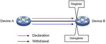
MRP messages
MRP exchanges information among MRP participants by advertising MRP messages, including Join, New, Leave, and LeaveAll. Join and New messages are declarations, and Leave and LeaveAll messages are withdrawals. As an MRP application, MVRP also uses MRP messages for information exchange.
1. Join message
An MRP participant sends Join messages when it wishes to declare its attribute values and receives Join messages from other MRP participants. When receiving a Join message, an MRP participant sends a Join message to all participants except the sender.
Join messages fall into the following types:
? JoinEmpty—An MRP participant sends JoinEmpty messages to declare attribute values that it has not registered.
? JoinIn—An MRP participant sends JoinIn messages to declare attribute values that it has registered.
2. New message
When the Multiple Spanning Tree Protocol (MSTP) topology changes, in other words, when an MSTP TcDetected event occurs, an MRP participant sends New messages to declare the topology change. On receiving a New message, an MRP participant sends a New message out each port except the receiving port. Similar to a Join message, a New message enables MRP participants to register attributes.
3. Leave message
An MRP participant sends Leave messages when it wishes to withdraw declarations of its attribute values and receives Leave messages from other participants. When receiving a Leave message, an MRP participant sends a Leave message to all participants except the sender.
4. LeaveAll message
Each MRP participant is configured with an individual LeaveAll timer. When the timer expires, the MRP participant sends LeaveAll messages to deregister all attributes, so that any other MRP participant can re-register all attributes. This process periodically clears the useless attributes in the network. On receiving a LeaveAll message, MRP determines whether to send a Join message to request the sender to re-register these attributes according to attribute status. On sending a LeaveAll message, MRP restarts the LeaveAll timer.
MRP timers
The implementation of MRP uses the following timers to control MRP message transmission.
1. Periodic timer
On startup, an MRP participant starts its own Periodic timer to control MRP message transmission. The MRP participant collects the MRP messages to be sent before the Periodic timer expires, and sends the MRP messages in as few packets as possible when the Periodic timer expires and meanwhile restarts the Periodic timer. This mechanism reduces the number of MRP protocol packets periodically sent.
|
|
NOTE: You can enable or disable the Periodic timer at the CLI. When you disable the Periodic timer, MRP will not send MRP messages. |
2. Join timer
The Join timer control the transmission of Join messages. To make sure that Join messages can be reliably transmitted to other participants, an MRP participant waits for a period of the Join timer after sending a Join message. If the participant receives JoinIn messages from other participants before the Join timer expires, the participant does not re-send the Join message. When both the Join timer and the Periodic timer expire, the participant re-sends the Join message.
3. Leave timer
The Leave timer controls the deregistration of attributes. When an MRP participant wishes other participants to deregister its attributes, it sends a Leave message. On receiving a Leave message, MRP starts the Leave timer, and deregisters the attributes if it does not receive any Join message for the attributes before the Leave timer expires.
4. LeaveAll timer
On startup, an MRP participant starts its own LeaveAll timer. When the LeaveAll timer expires, MRP sends out a LeaveAll message and restarts the LeaveAll timer. On receiving the LeaveAll message, other participants re-register all the attributes and re-start their LeaveAll timer.
|
|
NOTE: Though MRP participants throughout the network may be configured with different LeaveAll timers, an MRP participant sends LeaveAll messages at the smallest interval among the neighboring participants’ LeaveAll timers. At the next startup, the LeaveAll timer of each participant randomly changes within a certain range. |
MRP protocol packet encapsulation format
Figure 2 MRP protocol packet encapsulation format
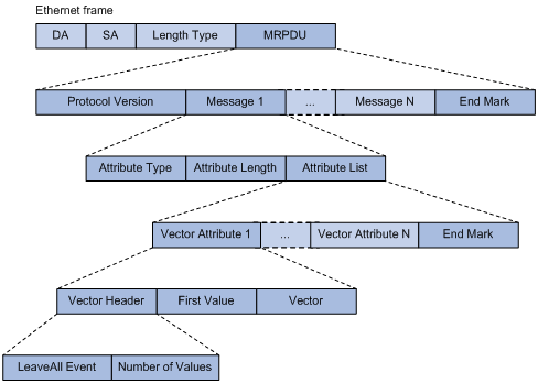
Figure 2 shows the format of an MRP protocol packet encapsulated in an IEEE 802.3 Ethernet frame.
Table 1 MRP protocol packet fields
|
Field |
Description |
|
MRPDU |
MRP protocol data unit (MRPDU) encapsulated in the MRP protocol packet. |
|
Protocol Version |
Protocol version, which is 0. |
|
Message |
Attribute message, which comprises the Attribute Type, Attribute Length, and Attribute List fields. |
|
End Mark |
End mark of the MRPDU or an attribute list field. This field is fixed at 0x00. |
|
Attribute Type |
Attribute type, which is VID Vector specified by the value of 1. |
|
Attribute Length |
Length of the FirstValue field, which is 2 as specified by MVRP. |
|
Attribute List |
Attribute list, which comprises multiple attributes. |
|
Vector Attribute |
Vector attribute, which comprises the VectorHeader, FirstValue, and Vector fields. |
|
Vector Header |
Vector header, which comprises the LeaveAllEvent and NumberOfValues fields. |
|
FirstValue |
The first attribute value encapsulated in the MVRP protocol packet. |
|
Vector |
Attribute events, where each byte specifies three attribute events. The attribute events include: · 0x00—New operator · 0x01—JoinIn operator · 0x02—In operator · 0x03—JoinMt operator · 0x04—Mt operator · 0x05—Lv operator Assume that the three attribute events sharing a byte are A1, A2, and A3. The value of the byte A1A2A3 is ((A1 * 6 + A2) * 6) + A3, which ranges from 0 to 255. |
|
LeaveAll Event |
LeaveAll event indicator: · 0—Not a LeaveAll event · 1—A LeaveAll event |
|
Number of Values |
A 13-bit field, which shows the number of attribute values encoded in the Vector field. |
The destination MAC addresses of MRP protocol packets are multicast MAC addresses, and vary with MRP applications. For example, the destination MAC address is 01-80-C2-00-00-21 and the EtherType is 88F5 for MVRP protocol packets. When a device receives a packet from an MRP participant, it delivers the packet to the MRP application identified by the destination MAC address.
MVRP implementation
MVRP overview
As an MRP application, MVRP uses the operating mechanism of MRP to maintain and propagate dynamic VLAN registration information throughout the network.
In a LAN, each MVRP-enabled device can receive the VLAN registration information from other MVRP devices, and dynamically update its local database, including active VLANs and the ports through which a VLAN can be reached. This makes sure that all MVRP-enabled devices in a LAN maintain the same VLAN information.
The VLAN information propagated by MVRP includes not only locally, manually configured static VLAN information but also dynamic VLAN information from other devices.
MVRP implementation mechanisms
MVRP registers and deregisters VLAN attributes as follows:
· When a port receives the declaration of a VLAN attribute, the port registers the VLAN and joins the VLAN.
· When a port receives the withdrawal of a VLAN attribute, the port deregisters the VLAN and leaves the VLAN.
|
|
NOTE: Figure 1 shows a simple MVRP implementation on an MSTI. In a network with multiple MSTIs, VLAN registration and deregistration are performed on a per-MSTI basis. For more information about MSTIs, see the chapter “Configuring the spanning tree.” |
MVRP registration modes
VLANs created manually, locally are called “static VLANs”, and VLANs learned through MVRP are called “dynamic VLANs”. The following MVRP registration modes are available.
· Normal
A port in normal registration mode performs dynamic VLAN registrations and deregistrations, and sends declarations and withdrawals for dynamic and static VLANs.
· Fixed
A port in fixed registration mode disables deregistering dynamic VLANs, sends declarations for dynamic VLANs and static VLANs, and drops received MVRP protocol packets. As a result, a trunk port in fixed registration mode does not deregister or register dynamic VLANs.
· Forbidden
A port in forbidden registration mode disables registering dynamic VLANs, sends declarations for dynamic VLANs and static VLANs, and drops received MVRP protocol packets. As a result, a trunk port in forbidden registration mode does not register dynamic VLANs, and does not re-register a dynamic VLAN when the VLAN is deregistered.
Protocols and standards
· IEEE 802.1ak IEEE Standard for Local and Metropolitan Area Networks: Virtual Bridged Local Area Networks – Amendment 07: Multiple Registration Protocol
MVRP configuration task list
To configure MVRP, perform the following tasks:
|
Task |
Remarks |
|
Optional |
|
|
Optional |
|
|
Optional |
|
|
NOTE: · MVRP configuration made in Ethernet interface view or Layer 2 aggregate interface view takes effect on the current interface only; MVRP configuration made in port group view takes effect on all the member ports in the group. · MVRP configuration made on a member port in an aggregation group takes effect only after the port is removed from the aggregation group. |
Configuring MVRP
Before enabling MVRP on a port, you must enable MVRP globally. You can configure MVRP only on trunk ports, and you must assign the involved trunk ports to all dynamic VLANs.
|
|
CAUTION: · MVRP and service loopback are mutually exclusive. · MVRP can work with STP, RSTP, or MSTP, but not other link layer topology protocols, including PVST, RRPP, and Smart Link. Ports blocked by STP, RSTP, or MSTP can receive and send MVRP protocol packets. For more information about STP, RSTP, MSTP, and PVST, see the chapter “Configuring the spanning tree.” For more information about RRPP and Smart Link, see High Availability Configuration Guide. · Do not enable both MVRP and remote port mirroring on a port. Otherwise, MVRP may register the remote probe VLAN to unexpected ports, which would cause the monitor port to receive undesired duplicates. For more information about port mirroring, see Network Management and Monitoring Configuration Guide. · Enabling MVRP on a Layer 2 aggregate interface enables both the aggregate interface and all Selected member ports in the link aggregation group to participate in dynamic VLAN registration and deregistration. · MVRP runs on a per-MSTI basis. When configuring MVRP, make sure that all MSTIs in the network are effective and each MSTI is mapped to an existing VLAN on each device in the network. |
To configure MVRP:
|
Step |
Command |
Remarks |
|
1. Enter system view. |
system-view |
N/A |
|
2. Enable MVRP globally. |
mvrp global enable |
By default, MVRP is globally disabled. |
|
3. Enter interface view. |
·
Enter Layer 2 Ethernet interface view or Layer
2 aggregate interface view: ·
Enter port group view: |
Use one of the commands. |
|
4. Configure the port as a trunk port. |
port link-type trunk |
By default, the link type of a port is access. |
|
5. Configure the port to permit all VLANs. |
port trunk permit vlan all |
By default, a trunk port permits only VLAN 1. |
|
6. Enable MVRP on the port. |
mvrp enable |
By default, MVRP is disabled on a port. |
|
7. Set the MVRP registration mode. |
mvrp registration { fixed | forbidden | normal } |
Optional. The default setting is normal registration mode. |
|
|
NOTE: For more information about the port link-type trunk and port trunk permit vlan all commands, see Layer 2—LAN Switching Command Reference. |
Configuring MRP timers
|
|
NOTE: · The MRP timers apply to all MRP applications, for example, MVRP, on a port. To avoid frequent VLAN registrations and deregistrations, use the same MRP timers throughout the network. · Each port maintains its own Periodic, Join, and LeaveAll timers, and each attribute of a port maintains a Leave timer. |
To configure MRP timers:
|
Use the command… |
Remarks |
|
|
1. Enter system view |
system-view |
N/A |
|
2. Enter interface view |
·
Enter Layer 2 Ethernet interface view or Layer
2 aggregate interface view: ·
Enter port group view: |
Use one of the commands. |
|
3. Configure the LeaveAll timer |
mrp timer leaveall timer-value |
Optional. The default setting is 1000 centiseconds. |
|
4. Configure the Join timer |
mrp timer join timer-value |
Optional. The default setting is 20 centiseconds. |
|
5. Configure the Leave timer |
mrp timer leave timer-value |
Optional. The default setting is 60 centiseconds. |
|
6. Configure the Periodic timer |
mrp timer periodic timer-value |
Optional. The default setting is 100 centiseconds. |
Table 2 shows the value ranges for MRP timers (including Join, Leave, and LeaveAll timers) and their dependencies.
· If you set a timer to a value beyond the allowed value range, your configuration will fail. To do that, you can change the allowed value range by tuning the value of another related timer.
· To restore the default settings of the timers, restore the Join timer first, followed by the Leave and LeaveAll timers. You can restore the Periodic timer to the default at any time.
Table 2 Dependencies of the MRP timers
Enabling GVRP compatibility
|
|
NOTE: · With GVRP compatibility enabled, MVRP can work with only STP or RSTP rather than MSTP. In this case, if MVRP and MSTP run at the same time, the network might fail to work properly. · With GVRP compatibility enabled, H3C recommends that you disable the Periodic timer for MVRP. Otherwise, the VLAN status might change frequently when the system is busy. |
MVRP can be compatible with GVRP. When the peer device supports GVRP, you can enable GVRP compatibility on the local end, so that the local end can receive and send MVRP and GVRP protocol packets at the same time.
To enable GVRP compatibility:
|
Step |
Command |
Remarks |
|
1. Enter system view |
system-view |
N/A |
|
2. Enable GVRP compatibility |
mvrp gvrp-compliance enable |
By default, GVRP compatibility is disabled. |
Displaying and maintaining MVRP
|
Task |
Command |
Remarks |
|
Display the MVRP status of the specified port and each MVRP interface in the specified VLAN. |
display mvrp state interface interface-type interface-number vlan vlan-id [ | { begin | exclude | include } regular-expression ] |
Available in any view |
|
Display the MVRP running status. |
display mvrp running-status [ interface interface-list ] [ | { begin | exclude | include } regular-expression ] |
Available in any view |
|
Display the MVRP statistics. |
display mvrp statistics [ interface interface-list ] [ | { begin | exclude | include } regular-expression ] |
Available in any view |
|
Display the dynamic VLAN operation information of the specified port. |
display mvrp vlan-operation interface interface-type interface-number [ | { begin | exclude | include } regular-expression ] |
Available in any view |
|
Clear the MVRP statistics of the specified ports. |
reset mvrp statistics [ interface interface-list ] |
Available in user view |
MVRP configuration examples
Configuration example for MVRP in normal registration mode
Network requirements
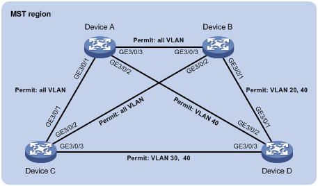
As shown in Figure 3, configure MSTP, map VLAN 10 to MSTI 1, map VLAN 20 MST 2, and map the other VLANs to MSTI 0.
Configure MVRP and set the MVRP registration mode to normal, so that Device A, Device B, Device C, and Device D can register and deregister dynamic and static VLANs and keep identical VLAN configuration for each MSTI.
Configuration procedure
1. Configure Device A:
# Enter MST region view.
<DeviceA> system-view
[DeviceA] stp region-configuration
# Configure the MST region name, VLAN-to-instance mappings, and revision level.
[DeviceA-mst-region] region-name example
[DeviceA-mst-region] instance 1 vlan 10
[DeviceA-mst-region] instance 2 vlan 20
[DeviceA-mst-region] revision-level 0
# Manually activate the MST region configuration.
[DeviceA-mst-region] active region-configuration
[DeviceA-mst-region] quit
# Configure Device A as the primary root bridge of MSTI 1.
[DeviceA] stp instance 1 root primary
# Globally enable the spanning tree feature.
[DeviceA] stp enable
# Globally enable MVRP.
[DeviceA] mvrp global enable
# Configure port GigabitEthernet 3/0/1 as a trunk port, and configure it to permit all VLANs.
[DeviceA] interface GigabitEthernet 3/0/1
[DeviceA-GigabitEthernet3/0/1] port link-type trunk
[DeviceA-GigabitEthernet3/0/1] port trunk permit vlan all
# Enable MVRP on port GigabitEthernet 3/0/1.
[DeviceA-GigabitEthernet3/0/1] mvrp enable
[DeviceA-GigabitEthernet3/0/1] quit
# Configure port GigabitEthernet 3/0/2 as a trunk port, and configure it to permit VLAN 40.
[DeviceA] interface GigabitEthernet 3/0/2
[DeviceA-GigabitEthernet3/0/2] port link-type trunk
[DeviceA-GigabitEthernet3/0/2] port trunk permit vlan 40
# Enable MVRP on port GigabitEthernet 3/0/2.
[DeviceA-GigabitEthernet3/0/2] mvrp enable
[DeviceA-GigabitEthernet3/0/2] quit
# Configure port GigabitEthernet 3/0/3 as a trunk port, and configure it to permit all VLANs.
[DeviceA] interface GigabitEthernet 3/0/3
[DeviceA-GigabitEthernet3/0/3] port link-type trunk
[DeviceA-GigabitEthernet3/0/3] port trunk permit vlan all
# Enable MVRP on port GigabitEthernet 3/0/3.
[DeviceA-GigabitEthernet3/0/3] mvrp enable
[DeviceA-GigabitEthernet3/0/3] quit
# Create VLAN 10.
[DeviceA] vlan 10
[DeviceA-vlan10] quit
2. Configure Device B:
# Enter MST region view.
<DeviceB> system-view
[DeviceB] stp region-configuration
# Configure the MST region name, VLAN-to-instance mappings, and revision level.
[DeviceB-mst-region] region-name example
[DeviceB-mst-region] instance 1 vlan 10
[DeviceB-mst-region] instance 2 vlan 20
[DeviceB-mst-region] revision-level 0
# Manually activate the MST region configuration.
[DeviceB-mst-region] active region-configuration
[DeviceB-mst-region] quit
# Configure Device B as the primary root bridge of MSTI 2.
[DeviceB] stp instance 2 root primary
# Globally enable the spanning tree feature.
[DeviceB] stp enable
# Globally enable MVRP.
[DeviceB] mvrp global enable
# Configure port GigabitEthernet 3/0/1 as a trunk port, and configure it to permit VLANs 20 and 40.
[DeviceB] interface GigabitEthernet 3/0/1
[DeviceB-GigabitEthernet3/0/1] port link-type trunk
[DeviceB-GigabitEthernet3/0/1] port trunk permit vlan 20 40
# Enable MVRP on port GigabitEthernet 3/0/1.
[DeviceB-GigabitEthernet3/0/1] mvrp enable
[DeviceB-GigabitEthernet3/0/1] quit
# Configure port GigabitEthernet 3/0/2 as a trunk port, and configure it to permit all VLANs.
[DeviceB] interface GigabitEthernet 3/0/2
[DeviceB-GigabitEthernet3/0/2] port link-type trunk
[DeviceB-GigabitEthernet3/0/2] port trunk permit vlan all
# Enable MVRP on port GigabitEthernet 3/0/2.
[DeviceB-GigabitEthernet3/0/2] mvrp enable
[DeviceB-GigabitEthernet3/0/2] quit
# Configure port GigabitEthernet 3/0/3 as a trunk port, and configure it to permit all VLANs.
[DeviceB] interface GigabitEthernet 3/0/3
[DeviceB-GigabitEthernet3/0/3] port link-type trunk
[DeviceB-GigabitEthernet3/0/3] port trunk permit vlan all
# Enable MVRP on port GigabitEthernet 3/0/3.
[DeviceB-GigabitEthernet3/0/3] mvrp enable
[DeviceB-GigabitEthernet3/0/3] quit
# Create VLAN 20.
[DeviceB] vlan 20
[DeviceB-vlan20] quit
3. Configure Device C:
# Enter MST region view.
<DeviceC> system-view
[DeviceC] stp region-configuration
# Configure the MST region name, VLAN-to-instance mappings, and revision level.
[DeviceC-mst-region] region-name example
[DeviceC-mst-region] instance 1 vlan 10
[DeviceC-mst-region] instance 2 vlan 20
[DeviceC-mst-region] revision-level 0
# Manually activate the MST region configuration.
[DeviceC-mst-region] active region-configuration
[DeviceC-mst-region] quit
# Globally enable the spanning tree feature.
[DeviceC] stp enable
# Globally enable MVRP.
[DeviceC] mvrp global enable
# Configure port GigabitEthernet 3/0/1 as a trunk port, and configure it to permit all VLANs.
[DeviceC] interface GigabitEthernet 3/0/1
[DeviceC-GigabitEthernet3/0/1] port link-type trunk
[DeviceC-GigabitEthernet3/0/1] port trunk permit vlan all
# Enable MVRP on port GigabitEthernet 3/0/1.
[DeviceC-GigabitEthernet3/0/1] mvrp enable
[DeviceC-GigabitEthernet3/0/1] quit
# Configure port GigabitEthernet 3/0/2 as a trunk port, and configure it to permit all VLANs.
[DeviceC] interface GigabitEthernet 3/0/2
[DeviceC-GigabitEthernet3/0/2] port link-type trunk
[DeviceC-GigabitEthernet3/0/2] port trunk permit vlan all
# Enable MVRP on port GigabitEthernet 3/0/2.
[DeviceC-GigabitEthernet3/0/2] mvrp enable
[DeviceC-GigabitEthernet3/0/2] quit
# Configure port GigabitEthernet 3/0/3 as a trunk port, and configure it to permit VLANs 30 and 40.
[DeviceC] interface GigabitEthernet 3/0/3
[DeviceC-GigabitEthernet3/0/3] port link-type trunk
[DeviceC-GigabitEthernet3/0/3] port trunk permit vlan 30 40
# Enable MVRP on port GigabitEthernet 3/0/3.
[DeviceC-GigabitEthernet3/0/3] mvrp enable
[DeviceC-GigabitEthernet3/0/3] quit
4. Configure Device D:
# Enter MST region view.
<DeviceD> system-view
[DeviceD] stp region-configuration
# Configure the MST region name, VLAN-to-instance mappings, and revision level.
[DeviceD-mst-region] region-name example
[DeviceD-mst-region] instance 1 vlan 10
[DeviceD-mst-region] instance 2 vlan 20
[DeviceD-mst-region] revision-level 0
# Manually activate the MST region configuration.
[DeviceD-mst-region] active region-configuration
[DeviceD-mst-region] quit
# Globally enable the spanning tree feature.
[DeviceD] stp enable
# Globally enable MVRP.
[DeviceD] mvrp global enable
# Configure port GigabitEthernet 3/0/1 as a trunk port, and configure it to permit VLANs 20 and 40.
[DeviceD] interface GigabitEthernet 3/0/1
[DeviceD-GigabitEthernet3/0/1] port link-type trunk
[DeviceD-GigabitEthernet3/0/1] port trunk permit vlan 20 40
# Enable MVRP on port GigabitEthernet 3/0/1.
[DeviceD-GigabitEthernet3/0/1] mvrp enable
[DeviceD-GigabitEthernet3/0/1] quit
# Configure port GigabitEthernet 3/0/2 as a trunk port, and configure it to permit VLAN 40.
[DeviceD] interface GigabitEthernet 3/0/2
[DeviceD-GigabitEthernet3/0/2] port link-type trunk
[DeviceD-GigabitEthernet3/0/2] port trunk permit vlan 40
# Enable MVRP on port GigabitEthernet 3/0/2.
[DeviceD-GigabitEthernet3/0/2] mvrp enable
[DeviceD-GigabitEthernet3/0/2] quit
# Configure port GigabitEthernet 3/0/3 as a trunk port, and configure it to permit VLANs 30 and 40.
[DeviceD] interface GigabitEthernet 3/0/3
[DeviceD-GigabitEthernet3/0/3] port link-type trunk
[DeviceD-GigabitEthernet3/0/3] port trunk permit vlan 30 40
# Enable MVRP on port GigabitEthernet 3/0/3.
[DeviceD-GigabitEthernet3/0/3] mvrp enable
[DeviceD-GigabitEthernet3/0/3] quit
5. Verify the configuration:
Use the display mvrp running-status command to display the local MVRP VLAN information to verify whether the configuration takes effect.
# Check the local VLAN information on Device A.
[DeviceA] display mvrp running-status
-------[MVRP Global Info]-------
Global Status : Enabled
Compliance-GVRP : False
----[GigabitEthernet3/0/1] ----
Config Status : Enabled
Running Status : Enabled
Join Timer : 20 (centiseconds)
Leave Timer : 60 (centiseconds)
Periodic Timer : 100 (centiseconds)
LeaveAll Timer : 1000 (centiseconds)
Registration Type : Normal
Local VLANs :
1(default),
----[GigabitEthernet3/0/2] ----
Config Status : Enabled
Running Status : Enabled
Join Timer : 20 (centiseconds)
Leave Timer : 60 (centiseconds)
Periodic Timer : 100 (centiseconds)
LeaveAll Timer : 1000 (centiseconds)
Registration Type : Normal
Local VLANs :
1(default),
----[GigabitEthernet3/0/3] ----
Config Status : Enabled
Running Status : Enabled
Join Timer : 20 (centiseconds)
Leave Timer : 60 (centiseconds)
Periodic Timer : 100 (centiseconds)
LeaveAll Timer : 1000 (centiseconds)
Registration Type : Normal
Local VLANs :
1(default), 20,
The output shows that:
? Ports GigabitEthernet 3/0/1 and GigabitEthernet 3/0/2 have learned only VLAN 1 through MVRP.
? Port GigabitEthernet 3/0/3 has learned VLAN 1 and dynamic VLAN 20 created on Device B through MVRP.
# Check the local VLAN information on Device B.
[DeviceB] display mvrp running-status
-------[MVRP Global Info]-------
Global Status : Enabled
Compliance-GVRP : False
----[GigabitEthernet3/0/1] ----
Config Status : Enabled
Running Status : Enabled
Join Timer : 20 (centiseconds)
Leave Timer : 60 (centiseconds)
Periodic Timer : 100 (centiseconds)
LeaveAll Timer : 1000 (centiseconds)
Registration Type : Normal
Local VLANs :
1(default),
----[GigabitEthernet3/0/2] ----
Config Status : Enabled
Running Status : Enabled
Join Timer : 20 (centiseconds)
Leave Timer : 60 (centiseconds)
Periodic Timer : 100 (centiseconds)
LeaveAll Timer : 1000 (centiseconds)
Registration Type : Normal
Local VLANs :
1(default),
----[GigabitEthernet3/0/3] ----
Config Status : Enabled
Running Status : Enabled
Join Timer : 20 (centiseconds)
Leave Timer : 60 (centiseconds)
Periodic Timer : 100 (centiseconds)
LeaveAll Timer : 1000 (centiseconds)
Registration Type : Normal
Local VLANs :
1(default), 10,
The output shows that:
? Ports GigabitEthernet 3/0/1 and GigabitEthernet 3/0/2 have learned only VLAN 1 through MVRP.
? Port GigabitEthernet 3/0/3 has learned VLAN 1 and dynamic VLAN 10 created on Device A through MVRP.
# Check the local VLAN information on Device C.
[DeviceC] display mvrp running-status
-------[MVRP Global Info]-------
Global Status : Enabled
Compliance-GVRP : False
----[GigabitEthernet3/0/1] ----
Config Status : Enabled
Running Status : Enabled
Join Timer : 20 (centiseconds)
Leave Timer : 60 (centiseconds)
Periodic Timer : 100 (centiseconds)
LeaveAll Timer : 1000 (centiseconds)
Registration Type : Normal
Local VLANs :
1(default), 10,
----[GigabitEthernet3/0/2] ----
Config Status : Enabled
Running Status : Enabled
Join Timer : 20 (centiseconds)
Leave Timer : 60 (centiseconds)
Periodic Timer : 100 (centiseconds)
LeaveAll Timer : 1000 (centiseconds)
Registration Type : Normal
Local VLANs :
1(default), 20,
----[GigabitEthernet3/0/3] ----
Config Status : Enabled
Running Status : Enabled
Join Timer : 20 (centiseconds)
Leave Timer : 60 (centiseconds)
Periodic Timer : 100 (centiseconds)
LeaveAll Timer : 1000 (centiseconds)
Registration Type : Normal
Local VLANs :
1(default),
The output shows that:
? Port GigabitEthernet 3/0/1 has learned VLAN 1 and dynamic VLAN 10 created on Device A through MVRP.
? Port GigabitEthernet 3/0/2 has learned VLAN 1 and dynamic VLAN 20 created on Device B through MVRP.
? Port GigabitEthernet 3/0/3 has learned only VLAN 1 through MVRP.
# Check the local VLAN information on Device D.
[DeviceD] display mvrp running-status
-------[MVRP Global Info]-------
Global Status : Enabled
Compliance-GVRP : False
----[GigabitEthernet3/0/1] ----
Config Status : Enabled
Running Status : Enabled
Join Timer : 20 (centiseconds)
Leave Timer : 60 (centiseconds)
Periodic Timer : 100 (centiseconds)
LeaveAll Timer : 1000 (centiseconds)
Registration Type : Normal
Local VLANs :
1(default), 20,
----[GigabitEthernet3/0/2] ----
Config Status : Enabled
Running Status : Enabled
Join Timer : 20 (centiseconds)
Leave Timer : 60 (centiseconds)
Periodic Timer : 100 (centiseconds)
LeaveAll Timer : 1000 (centiseconds)
Registration Type : Normal
Local VLANs :
1(default),
----[GigabitEthernet3/0/3] ----
Config Status : Enabled
Running Status : Enabled
Join Timer : 20 (centiseconds)
Leave Timer : 60 (centiseconds)
Periodic Timer : 100 (centiseconds)
LeaveAll Timer : 1000 (centiseconds)
Registration Type : Normal
Local VLANs :
1(default),
The output shows that:
? Port GigabitEthernet 3/0/1 has learned VLAN 1 and dynamic VLAN 20 created on Device B through MVRP.
? Ports GigabitEthernet 3/0/2 and GigabitEthernet 3/0/3 have learned only VLAN 1 through MVRP.
Configuration example for MVRP in fixed registration mode
Network requirements
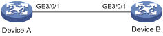
As shown in Figure 4, enable MVRP and set the MVRP registration mode to fixed on GigabitEthernet 3/0/1 on Device B, so that the dynamic VLANs on Device B are not deregistered.
Configuration procedure
1. Configure Device A:
# Globally enable MVRP.
<DeviceA> system-view
[DeviceA] mvrp global enable
# Configure GigabitEthernet 3/0/1 as a trunk port, and configure it to permit all VLANs.
[DeviceA] interface GigabitEthernet 3/0/1
[DeviceA-GigabitEthernet3/0/1] port link-type trunk
[DeviceA-GigabitEthernet3/0/1] port trunk permit vlan all
# Enable MVRP on GigabitEthernet 3/0/1.
[DeviceA-GigabitEthernet3/0/1] mvrp enable
[DeviceA-GigabitEthernet3/0/1] quit
# Create VLAN 2.
[DeviceA] vlan 2
[DeviceA-vlan2] quit
2. Configure Device B:
# Globally enable MVRP.
<DeviceB> system-view
[DeviceB] mvrp global enable
# Configure GigabitEthernet 3/0/1 as a trunk port, and configure it to permit all VLANs.
[DeviceB] interface GigabitEthernet 3/0/1
[DeviceB-GigabitEthernet3/0/1] port link-type trunk
[DeviceB-GigabitEthernet3/0/1] port trunk permit vlan all
# Enable MVRP on GigabitEthernet 3/0/1.
[DeviceB-GigabitEthernet3/0/1] mvrp enable
[DeviceB-GigabitEthernet3/0/1] quit
# Create VLAN 3.
[DeviceB] vlan 3
[DeviceB-vlan3] quit
3. Verify the configuration:
Use the display mvrp running-status command to display the local MVRP VLAN information to verify whether the configuration takes effect.
# Check the local VLAN information on GigabitEthernet 3/0/1 of Device A.
[DeviceA] display mvrp running-status
-------[MVRP Global Info]-------
Global Status : Enabled
Compliance-GVRP : False
----[GigabitEthernet3/0/1] ----
Config Status : Enabled
Running Status : Enabled
Join Timer : 20 (centiseconds)
Leave Timer : 60 (centiseconds)
Periodic Timer : 100 (centiseconds)
LeaveAll Timer : 1000 (centiseconds)
Registration Type : Normal
Local VLANs :
1(default), 3,
The output shows that GigabitEthernet 3/0/1 has learned VLAN 1 and dynamic VLAN 3 created on Device B through MVRP.
# Check the local VLAN information on GigabitEthernet 3/0/1 of Device B.
[DeviceB] display mvrp running-status
-------[MVRP Global Info]-------
Global Status : Enabled
Compliance-GVRP : False
----[GigabitEthernet3/0/1] ----
Config Status : Enabled
Running Status : Enabled
Join Timer : 20 (centiseconds)
Leave Timer : 60 (centiseconds)
Periodic Timer : 100 (centiseconds)
LeaveAll Timer : 1000 (centiseconds)
Registration Type : Normal
Local VLANs :
1(default), 2,
The output shows that GigabitEthernet 3/0/1 has learned VLAN 1 and dynamic VLAN 2 created on Device A through MVRP.
4. Set the MVRP registration mode to fixed on GigabitEthernet 3/0/1 of Device B:
# Set the MVRP registration mode to fixed on GigabitEthernet 3/0/1.
[DeviceB] interface GigabitEthernet 3/0/1
[DeviceB-GigabitEthernet3/0/1] mvrp registration fixed
[DeviceB-GigabitEthernet3/0/1] quit
# Check the local VLAN information on GigabitEthernet 3/0/1 of Device B.
[DeviceB] display mvrp running-status
-------[MVRP Global Info]-------
Global Status : Enabled
Compliance-GVRP : False
----[GigabitEthernet3/0/1] ----
Config Status : Enabled
Running Status : Enabled
Join Timer : 20 (centiseconds)
Leave Timer : 60 (centiseconds)
Periodic Timer : 100 (centiseconds)
LeaveAll Timer : 1000 (centiseconds)
Registration Type : Fixed
Local VLANs :
1(default), 2,
The output shows that the local VLAN information on GigabitEthernet 3/0/1 is the same that that before the MVRP registration mode is set to fixed.
5. Delete VLAN 2 on Device A:
# Delete VLAN 2 on Device A.
[DeviceA] undo vlan 2
# Check the local VLAN information on GigabitEthernet 3/0/1 of Device B.
[DeviceB] display mvrp running-status
-------[MVRP Global Info]-------
Global Status : Enabled
Compliance-GVRP : False
----[GigabitEthernet3/0/1] ----
Config Status : Enabled
Running Status : Enabled
Join Timer : 20 (centiseconds)
Leave Timer : 60 (centiseconds)
Periodic Timer : 100 (centiseconds)
LeaveAll Timer : 1000 (centiseconds)
Registration Type : Fixed
Local VLANs :
1(default), 2,
The output shows that the dynamic VLAN information on GigabitEthernet 3/0/1 does not change after VLAN 2 is deleted from Device A.
Configuration example for MVRP in forbidden registration mode
Network requirements
As shown in Figure 5, enable MVRP and set the MVRP registration mode to forbidden on GigabitEthernet 3/0/1 of Device B, so that Device B does not learn dynamic VLANs.

Configuration procedure
1. Configure Device A:
# Globally enable MVRP.
<DeviceA> system-view
[DeviceA] mvrp global enable
# Configure GigabitEthernet 3/0/1 as a trunk port, and configure it to permit all VLANs.
[DeviceA] interface GigabitEthernet 3/0/1
[DeviceA-GigabitEthernet3/0/1] port link-type trunk
[DeviceA-GigabitEthernet3/0/1] port trunk permit vlan all
# Enable MVRP on GigabitEthernet 3/0/1.
[DeviceA-GigabitEthernet3/0/1] mvrp enable
[DeviceA-GigabitEthernet3/0/1] quit
# Create static VLAN 2.
[DeviceA] vlan 2
[DeviceA-vlan2] quit
2. Configure Device B:
# Globally enable MVRP.
<DeviceB> system-view
[DeviceB] mvrp global enable
# Configure GigabitEthernet 3/0/1 as a trunk port, and configure it to permit all VLANs.
[DeviceB] interface GigabitEthernet 3/0/1
[DeviceB-GigabitEthernet3/0/1] port link-type trunk
[DeviceB-GigabitEthernet3/0/1] port trunk permit vlan all
# Enable MVRP on GigabitEthernet 3/0/1.
[DeviceB-GigabitEthernet3/0/1] mvrp enable
[DeviceB-GigabitEthernet3/0/1] quit
# Create VLAN 3.
[DeviceB] vlan 3
[DeviceB-vlan3] quit
Use the display mvrp running-status command to display the local MVRP VLAN information to verify whether the configuration takes effect.
# Check the local VLAN information on GigabitEthernet 3/0/1 of Device A.
[DeviceA] display mvrp running-status
-------[MVRP Global Info]-------
Global Status : Enabled
Compliance-GVRP : False
----[GigabitEthernet3/0/1] ----
Config Status : Enabled
Running Status : Enabled
Join Timer : 20 (centiseconds)
Leave Timer : 60 (centiseconds)
Periodic Timer : 100 (centiseconds)
LeaveAll Timer : 1000 (centiseconds)
Registration Type : Normal
Local VLANs :
1(default), 3,
The output shows that GigabitEthernet 3/0/1 has learned VLAN 1 and dynamic VLAN 3 created on Device B through MVRP.
# Check the local VLAN information on GigabitEthernet 3/0/1 of Device B.
[DeviceB] display mvrp running-status
-------[MVRP Global Info]-------
Global Status : Enabled
Compliance-GVRP : False
----[GigabitEthernet3/0/1] ----
Config Status : Enabled
Running Status : Enabled
Join Timer : 20 (centiseconds)
Leave Timer : 60 (centiseconds)
Periodic Timer : 100 (centiseconds)
LeaveAll Timer : 1000 (centiseconds)
Registration Type : Normal
Local VLANs :
1(default), 2,
The output shows that GigabitEthernet 3/0/1 has learned VLAN 1 and dynamic VLAN 2 created on Device A through MVRP.
4. Set the MVRP registration mode to forbidden on GigabitEthernet 3/0/1 of Device B:
# Set the MVRP registration mode to forbidden on GigabitEthernet 3/0/1 of Device B.
[DeviceB] interface GigabitEthernet 3/0/1
[DeviceB-GigabitEthernet3/0/1] mvrp registration forbidden
# Several seconds after the LeaveAll timer (10 seconds by default) expires, check the local VLAN information on GigabitEthernet 3/0/1 of Device B.
[DeviceB-GigabitEthernet3/0/1] display mvrp running-status
-------[MVRP Global Info]-------
Global Status : Enabled
Compliance-GVRP : False
----[GigabitEthernet3/0/1] ----
Config Status : Enabled
Running Status : Enabled
Join Timer : 20 (centiseconds)
Leave Timer : 60 (centiseconds)
Periodic Timer : 100 (centiseconds)
LeaveAll Timer : 1000 (centiseconds)
Registration Type : Forbidden
Local VLANs :
1(default),
The output shows that the local VLAN information on GigabitEthernet 3/0/1 of Device A does not contain VLAN 2 and the port configured with forbidden MVRP registration mode does not reregister dynamic VLANs that have been deregistered.