- Table of Contents
-
- 04-Layer 2 - LAN Switching Configuration Guide
- 00-Preface
- 01-VLAN Configuration
- 02-MAC Address Table Configuration
- 03-Spanning Tree Configuration
- 04-Ethernet Link Aggregation Configuration
- 05-Port Isolation Configuration
- 06-QinQ Configuration
- 07-VLAN Mapping Configuration
- 08-BPDU Tunneling Configuration
- 09-GVRP Configuration
- 10-Loopback Detection Configuration
- 11-MAC-in-MAC Configuration
- 12-LLDP Configuration
- 13-MVRP Configuration
- Related Documents
-
| Title | Size | Download |
|---|---|---|
| 03-Spanning Tree Configuration | 646.9 KB |
Contents
Calculation process of the STP algorithm
STP, RSTP, and PVST limitations
Implementation of MSTP on devices
Spanning tree configuration task lists
Setting the spanning tree mode
Configuring the root bridge or a secondary root bridge
Configuring the switch priority
Configuring the maximum hops of an MST region
Configuring the network diameter of a switched network
Configuring spanning tree timers
Configuring the timeout factor
Configuring the maximum port rate
Configuring path costs of ports
Configuring the port link type
Configuring the mode a port uses to recognize/send MSTP packets
Enabling the spanning tree feature
Configuring the VLAN Ignore feature
Configuring No Agreement Check
Configuring protection functions
Displaying and maintaining the spanning tree
Spanning tree configuration examples
|
|
NOTE: The switch operates in IRF or standalone (the default) mode. For more information about the IRF mode, see IRF Configuration Guide. |
As a Layer 2 management protocol, the Spanning Tree Protocol (STP) eliminates Layer 2 loops by selectively blocking redundant links in a network, and also allows for link redundancy.
Recent versions of STP include the Rapid Spanning Tree Protocol (RSTP), the Multiple Spanning Tree Protocol (MSTP), and the Per VLAN Spanning Tree Protocol (PVST).
STP
STP was developed based on the 802.1d standard of IEEE to eliminate loops at the data link layer in a local area network (LAN). Networks often have redundant links as backups in case of failures, but loops are a very serious problem. Devices running STP detect loops in the network by exchanging information with one another, and eliminate loops by selectively blocking certain ports to prune the loop structure into a loop-free tree structure. This avoids proliferation and infinite cycling of packets that would occur in a loop network and prevents decreased device performance caused by receiving duplicate packets.
In the narrow sense, STP refers to IEEE 802.1d STP. In the broad sense, STP refers to the IEEE 802.1d STP and various enhanced spanning tree protocols derived from that protocol.
STP protocol packets
STP uses bridge protocol data units (BPDUs), also known as configuration messages, as its protocol packets. Throughout this document, BPDUs refer to STP BPDUs.
STP-enabled network devices exchange BPDUs to establish a spanning tree. BPDUs contain sufficient information for the network devices to complete spanning tree calculation.
STP uses the following types of BPDUs:
· Configuration BPDUs, used for calculating a spanning tree and maintaining the spanning tree topology.
· Topology change notification (TCN) BPDUs, which notify network devices of network topology changes.
A configuration BPDU contains the following information for network devices to complete spanning tree calculation:
· Root bridge ID—Comprises the priority and MAC address of the root bridge.
· Root path cost—The cost of the path to the root bridge.
· Designated bridge ID—Comprises the priority and MAC address of the designated bridge.
· Designated port ID—Comprises the port priority and global port number.
· Message age—The times that the configuration BPDU has been forwarded on the network.
· Max age—The maximum age of the configuration BPDU.
· Hello time—The transmission interval of the configuration BPDU.
· Forward delay—The delay before a port transitions to the forwarding state.
Basic concepts in STP
Root bridge
A tree network must have a root bridge.
There is only one root bridge in the entire network. The root bridge is not permanent, but can change with changes of the network topology.
Upon initialization of a network, each device generates and periodically sends out configuration BPDUs with itself as the root bridge. After network convergence, only the root bridge generates and periodically sends out configuration BPDUs. The other devices only forward the BPDUs.
Root port
Designated bridge and designated port
Table 1 Description of designated bridges and designated ports
|
Classification |
Designated bridge |
Designated port |
|
For a device |
A device directly connected with the local device and responsible for forwarding BPDUs to the local device |
The port through which the designated bridge forwards BPDUs to this device |
|
For a LAN |
The device responsible for forwarding BPDUs to this LAN segment |
The port through which the designated bridge forwards BPDUs to this LAN segment |
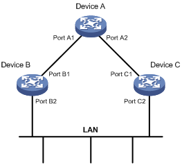
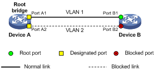
As shown in Figure 1, Device B and Device C are directly connected to a LAN. If Device A forwards BPDUs to Device B through port A1, the designated bridge for Device B is Device A, and the designated port of Device B is port A1 on Device A. If Device B forwards BPDUs to the LAN, the designated bridge for the LAN is Device B, and the designated port for the LAN is port B2 on Device B.
Figure 1 Designated bridges and designated ports
Path cost
Path cost is a reference value used for link selection in STP. STP calculates path costs to select the most robust links and blocks redundant links that are less robust, to prune the network into a loop-free tree.
Calculation process of the STP algorithm
The STP algorithm uses the following calculation process:
1. Initial state
2. Root bridge selection
Initially, each STP-enabled device on the network assumes itself to be the root bridge, with its own device ID as the root bridge ID. By exchanging configuration BPDUs, the devices compare their root bridge IDs to elect the device with the smallest root bridge ID as the root bridge.
3. Non-root bridge: selection of root port and designated ports
Table 2 describes the process of selecting the root port and designated ports.
Table 2 Selection of the root port and designated ports
|
Step |
Description |
|
1 |
A non-root-bridge device regards the port on which it received the optimum configuration BPDU as the root port. Table 3 describes how the optimum configuration BPDU is selected. |
|
2 |
Based on the configuration BPDU and the path cost of the root port, the device calculates a designated port configuration BPDU for each of its other ports. · The root bridge ID is replaced with that of the configuration BPDU of the root port. · The root path cost is replaced with that of the configuration BPDU of the root port plus the path cost of the root port. · The designated bridge ID is replaced with the ID of this device. · The designated port ID is replaced with the ID of this port. |
|
3 |
The device compares the calculated configuration BPDU with the configuration BPDU on the port whose port role is to be determined: · If the calculated configuration BPDU is superior, the device considers this port as the designated port, replaces the configuration BPDU on the port with the calculated configuration BPDU, and periodically sends out the calculated configuration BPDU. · If the configuration BPDU on the port is superior, the device blocks this port without updating its configuration BPDU. The blocked port can receive BPDUs, but cannot send BPDUs or forward data traffic. |
|
|
NOTE: When the network topology is stable, only the root port and designated ports forward user traffic, while other ports are all in the blocked state to receive BPDUs but not forward BPDUs or user traffic. |
Table 3 Selection of the optimum configuration BPDU
|
Step |
Actions |
|
1 |
Upon receiving a configuration BPDU on a port, the device compares the priority of the received configuration BPDU with that of the configuration BPDU generated by the port, and: · If the former priority is lower, the device discards the received configuration BPDU and keeps the configuration BPDU the port generated. · If the former priority is higher, the device replaces the content of the configuration BPDU generated by the port with the content of the received configuration BPDU. |
|
2 |
The device compares the configuration BPDUs of all the ports and chooses the optimum configuration BPDU. |
|
|
NOTE: The following are the principles of configuration BPDU comparison: · The configuration BPDU with the lowest root bridge ID has the highest priority. · If configuration BPDUs have the same root bridge ID, their root path costs are compared. For example, the root path cost in a configuration BPDU plus the path cost of a receiving port is S. The configuration BPDU with the smallest S value has the highest priority. · If all configuration BPDUs have the same ports value, their designated bridge IDs, designated port IDs, and the IDs of the receiving ports are compared in sequence. The configuration BPDU containing a smaller ID wins out. |
A tree-shape topology forms when the root bridge, root ports, and designated ports are selected.
The following describes with an example how the STP algorithm works.
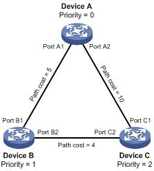
As shown in Figure 2, the priority values of Device A, Device B, and Device C are 0, 1, and 2, and the path costs of links among the three devices are 5, 10, and 4 respectively.
4. Initial state of each device
Table 4 Initial state of each device
|
Device |
Port name |
Configuration BPDU on the port |
|
Device A |
Port A1 |
{0, 0, 0, Port A1} |
|
Port A2 |
{0, 0, 0, Port A2} |
|
|
Device B |
Port B1 |
{1, 0, 1, Port B1} |
|
Port B2 |
{1, 0, 1, Port B2} |
|
|
Device C |
Port C1 |
{2, 0, 2, Port C1} |
|
Port C2 |
{2, 0, 2, Port C2} |
|
|
NOTE: In Table 4, each configuration BPDU contains the following fields: root bridge ID, root path cost, designated bridge ID, and designated port ID. |
5. Comparison process and result on each device
Table 5 Comparison process and result on each device
|
Device |
Comparison process |
Configuration BPDU on ports after comparison |
|
Device A |
· Port A1 receives the configuration BPDU of Port B1 {1, 0, 1, Port B1}, finds that its existing configuration BPDU {0, 0, 0, Port A1} is superior to the received configuration BPDU, and discards the received one. · Port A2 receives the configuration BPDU of Port C1 {2, 0, 2, Port C1}, finds that its existing configuration BPDU {0, 0, 0, Port A2} is superior to the received configuration BPDU, and discards the received one. · Device A finds that it is both the root bridge and designated bridge in the configuration BPDUs of all its ports, and considers itself as the root bridge. It does not change the configuration BPDU of any port and starts to periodically send out configuration BPDUs. |
· Port A1: {0, 0, 0, Port A1} · Port A2: {0, 0, 0, Port A2} |
|
Device B |
· Port B1 receives the configuration BPDU of Port A1 {0, 0, 0, Port A1}, finds that the received configuration BPDU is superior to its existing configuration BPDU {1, 0, 1, Port B1}, and updates its configuration BPDU. · Port B2 receives the configuration BPDU of Port C2 {2, 0, 2, Port C2}, finds that its existing configuration BPDU {1, 0, 1, Port B2} is superior to the received configuration BPDU, and discards the received one. |
· Port B1: {0, 0, 0, Port A1} · Port B2: {1, 0, 1, Port B2} |
|
· Device B compares the configuration BPDUs of all its ports, decides that the configuration BPDU of Port B1 is the optimum, and selects Port B1 as the root port with the configuration BPDU unchanged. · Based on the configuration BPDU and path cost of the root port, Device B calculates a designated port configuration BPDU for Port B2 {0, 5, 1, Port B2}, and compares it with the existing configuration BPDU of Port B2 {1, 0, 1, Port B2}. Device B finds that the calculated one is superior, decides that Port B2 is the designated port, replaces the configuration BPDU on Port B2 with the calculated one, and periodically sends out the calculated configuration BPDU. |
· Root port (Port B1): {0, 0, 0, Port A1} · Designated port (Port B2): {0, 5, 1, Port B2} |
|
|
Device C |
· Port C1 receives the configuration BPDU of Port A2 {0, 0, 0, Port A2}, finds that the received configuration BPDU is superior to its existing configuration BPDU {2, 0, 2, Port C1}, and updates its configuration BPDU. · Port C2 receives the original configuration BPDU of Port B2 {1, 0, 1, Port B2}, finds that the received configuration BPDU is superior to the existing configuration BPDU {2, 0, 2, Port C2}, and updates its configuration BPDU. |
· Port C1: {0, 0, 0, Port A2} · Port C2: {1, 0, 1, Port B2} |
|
· Device C compares the configuration BPDUs of all its ports, decides that the configuration BPDU of Port C1 is the optimum, and selects Port C1 as the root port with the configuration BPDU unchanged. · Based on the configuration BPDU and path cost of the root port, Device C calculates the configuration BPDU of Port C2 {0, 10, 2, Port C2}, and compares it with the existing configuration BPDU of Port C2 {1, 0, 1, Port B2}. Device C finds that the calculated configuration BPDU is superior to the existing one, selects Port C2 as the designated port, and replaces the configuration BPDU of Port C2 with the calculated one. |
· Root port (Port C1): {0, 0, 0, Port A2} · Designated port (Port C2): {0, 10, 2, Port C2} |
|
|
· Port C2 receives the updated configuration BPDU of Port B2 {0, 5, 1, Port B2}, finds that the received configuration BPDU is superior to its existing configuration BPDU {0, 10, 2, Port C2}, and updates its configuration BPDU. · Port C1 receives a periodic configuration BPDU {0, 0, 0, Port A2} from Port A2, finds that it is the same as the existing configuration BPDU, and discards the received one. |
· Port C1: {0, 0, 0, Port A2} · Port C2: {0, 5, 1, Port B2} |
|
|
· Device C finds that the root path cost of Port C1 (10) (root path cost of the received configuration BPDU (0) plus path cost of Port C1 (10)) is larger than that of Port C2 (9) (root path cost of the received configuration BPDU (5) plus path cost of Port C2 (4)), decides that the configuration BPDU of Port C2 is the optimum, and selects Port C2 as the root port with the configuration BPDU unchanged. · Based on the configuration BPDU and path cost of the root port, Device C calculates a designated port configuration BPDU for Port C1 {0, 9, 2, Port C1} and compares it with the existing configuration BPDU of Port C1 {0, 0, 0, Port A2}. Device C finds that the existing configuration BPDU is superior to the calculated one and blocks Port C1 with the configuration BPDU unchanged. Then Port C1 does not forward data until a spanning tree calculation process is triggered by a new event, for example, the link between Device B and Device C is down. |
· Blocked port (Port C1): {0, 0, 0, Port A2} · Root port (Port C2): {0, 5, 1, Port B2} |
|
|
NOTE: In Table 5, each configuration BPDU contains the following fields: root bridge ID, root path cost, designated bridge ID, and designated port ID. |
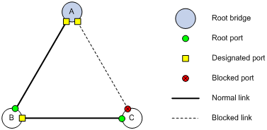
After the comparison processes described in Table 5, a spanning tree with Device A as the root bridge is established, and the topology is shown in Figure 3.
Figure 3 The final calculated spanning tree
|
|
NOTE: This example shows a simplified spanning tree calculation process. |
The configuration BPDU forwarding mechanism of STP
The configuration BPDUs of STP are forwarded following these guidelines:
· Upon network initiation, every switch regards itself as the root bridge, generates configuration BPDUs with itself as the root, and sends the configuration BPDUs at a regular hello interval.
· If it is the root port that received a configuration BPDU and the received configuration BPDU is superior to the configuration BPDU of the port, the device increases the message age carried in the configuration BPDU following a certain rule and starts a timer to time the configuration BPDU while sending out this configuration BPDU through the designated port.
· If the configuration BPDU received on a designated port has a lower priority than the configuration BPDU of the local port, the port immediately sends out its own configuration BPDU in response.
· If a path becomes faulty, the root port on this path no longer receives new configuration BPDUs and the old configuration BPDUs will be discarded due to timeout. The device generates a configuration BPDU with itself as the root and sends out the BPDUs and TCN BPDUs. This triggers a new spanning tree calculation process to establish a new path to restore the network connectivity.
However, the newly calculated configuration BPDU cannot be propagated throughout the network immediately, so the old root ports and designated ports that have not detected the topology change continue forwarding data along the old path. If the new root ports and designated ports begin to forward data as soon as they are elected, a temporary loop may occur.
STP timers
STP calculation involves the following timers: forward delay, hello time, and max age.
· Forward delay
Forward delay is the delay time for state transition.
A path failure can cause spanning tree re-calculation to adapt the spanning tree structure to the change. However, the resulting new configuration BPDU cannot propagate throughout the network immediately. If the newly elected root ports and designated ports start to forward data right away, a temporary loop is likely to occur.
For this reason, as a mechanism for state transition in STP, the newly elected root ports or designated ports require twice the forward delay time before transiting to the forwarding state to make sure that the new configuration BPDU has propagated throughout the network.
· Hello time
The device sends hello packets at the hello time interval to the neighboring devices to make sure that the paths are fault-free.
· Max age
The device uses the max age to determine whether a stored configuration BPDU has expired and discards it if the max age is exceeded.
RSTP
RSTP achieves rapid network convergence by allowing a newly elected root port or designated port to enter the forwarding state much faster than STP.
A newly elected RSTP root port rapidly enters the forwarding state if the old root port on the device has stopped forwarding data and the upstream designated port has started forwarding data.
A newly elected RSTP designated port rapidly enters the forwarding state if it is an edge port (which directly connects to a user terminal rather than to another network device or a shared LAN segment) or it connects to a point-to-point link (to another device). Edge ports directly enter the forwarding state. Connecting to a point-to-point link, a designated port enters the forwarding state immediately after the device receives a handshake response from the directly connected device.
PVST
PVST was introduced to improve link bandwidth usage in network environments where multiple virtual LANs (VLANs) exist. Unlike STP and RSTP whose bridges in a LAN must forward their VLAN packets in the same spanning tree, PVST allows each VLAN to build a separate spanning tree.
PVST uses the following BPDUs:
· STP BPDUs—Sent by access ports according to the VLAN status, or by trunk ports and hybrid ports according to the status of VLAN 1.
· PVST BPDUs—Sent by trunk port and hybrid ports according to the status of permitted VLANs except VLAN 1.
MSTP
STP, RSTP, and PVST limitations
STP does not support rapid state transition of ports. A newly elected port must wait twice the forward delay time before transiting to the forwarding state, even if it connects to a point-to-point link or is an edge port.
Although RSTP supports rapid network convergence, it has the same drawback as STP—All bridges within a LAN share the same spanning tree, and the packets of all VLANs are forwarded along the same spanning tree, so redundant links cannot be blocked based on VLAN and load sharing among VLANs cannot be implemented.
The number of PVST BPDUs generated grows with that of permitted VLANs on trunk ports. When the status of a trunk port transitions, network devices might be overloaded to re-calculate a large number of spanning trees.
MSTP features
Developed based on IEEE 802.1s, MSTP overcomes the limitations of STP, RSTP, and PVST. In addition to supporting rapid network convergence, it also provides a better load sharing mechanism for redundant links by allowing data flows of different VLANs to be forwarded along separate paths. For more information about VLANs, see the chapter “Configuring VLANs.”
MSTP includes the following features:
· MSTP divides a switched network into multiple regions, each containing multiple spanning trees that are independent of one another.
· MSTP supports mapping VLANs to spanning tree instances by means of a VLAN-to-instance mapping table. MSTP can reduce communication overheads and resource usage by mapping multiple VLANs to one instance.
· MSTP prunes a loop network into a loop-free tree, avoiding proliferation and endless cycling of packets in a loop network. In addition, it provides multiple redundant paths for data forwarding, supporting load balancing of VLAN data.
· MSTP is compatible with STP and RSTP, but is incompatible with PVST.
MSTP basic concepts
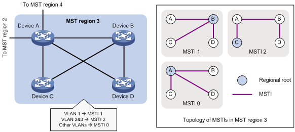
Figure 4 shows a switched network that comprises four MST regions, each MST region comprising four MSTP devices. Figure 5 shows the networking topology of MST region 3. This section describes some basic concepts of MSTP.
Figure 4 Basic concepts in MSTP
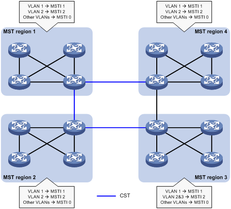
Figure 5 Network diagram and topology of MST region 3
MST region
A multiple spanning tree region (MST region) consists of multiple devices in a switched network and the network segments among them. All these devices have the following characteristics:
· A spanning tree protocol enabled
· Same region name
· Same VLAN-to-instance mapping configuration
· Same MSTP revision level
· Physically linked together
Multiple MST regions can exist in a switched network. You can assign multiple devices to the same MST region. In Figure 4, the switched network comprises four MST regions, MST region 1 through MST region 4, and all devices in each MST region have the same MST region configuration.
MSTI
MSTP can generate multiple spanning trees in an MST region, and each spanning tree is independent of another and maps to specific VLANs. Each spanning tree is referred to as a multiple spanning tree instance (MSTI).
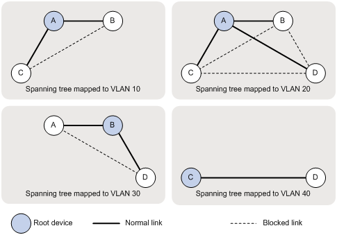
In Figure 5, MST region 3 comprises three MSTIs, MSTI 1, MSTI 2, and MSTI 0.
VLAN-to-instance mapping table
As an attribute of an MST region, the VLAN-to-instance mapping table describes the mapping relationships between VLANs and MSTIs.
In Figure 5, the VLAN-to-instance mapping table of MST region 3 is: VLAN 1 to MSTI 1, VLAN 2 and VLAN 3 to MSTI 2, and other VLANs to MSTI 0. MSTP achieves load balancing by means of the VLAN-to-instance mapping table.
CST
The common spanning tree (CST) is a single spanning tree that connects all MST regions in a switched network. If you regard each MST region as a device, the CST is a spanning tree calculated by these devices through STP or RSTP.
The blue lines in Figure 4 represent the CST.
IST
An internal spanning tree (IST) is a spanning tree that runs in an MST region. It is also called MSTI 0, a special MSTI to which all VLANs are mapped by default.
In Figure 4, MSTI 0 is the IST in MST region 3.
CIST
The common and internal spanning tree (CIST) is a single spanning tree that connects all devices in a switched network. It consists of the ISTs in all MST regions and the CST.
In Figure 4, the ISTs (MSTI 0) in all MST regions plus the inter-region CST constitute the CIST of the entire network.
Regional root
The root bridge of the IST or an MSTI within an MST region is the regional root of the IST or MSTI. Based on the topology, different spanning trees in an MST region may have different regional roots.
For example, in MST region 3 in Figure 5, the regional root of MSTI 1 is Device B, the regional root of MSTI 2 is Device C, and the regional root of MSTI 0 (also known as the IST) is Device A.
Common root bridge
The common root bridge is the root bridge of the CIST.
In Figure 4, for example, the common root bridge is a device in MST region 1.
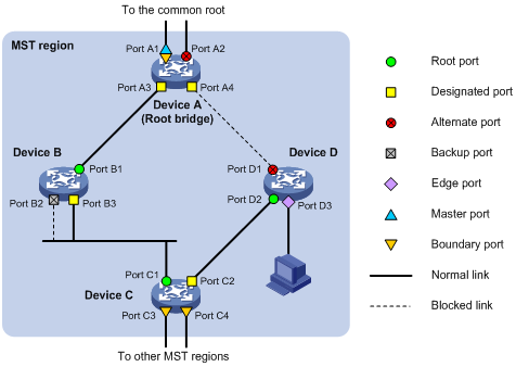
Port roles
A port can play different roles in different MSTIs. As shown in Figure 6, an MST region comprises Device A, Device B, Device C, and Device D. Port A1 and port A2 of Device A connect to the common root bridge. Port B2 and Port B3 of Device B form a loop. Port C3 and Port C4 of Device C connect to other MST regions. Port D3 of Device D directly connects to a host.
MSTP calculation involves these port roles:
· Root port—Forwards data for a non-root bridge to the root bridge. The root bridge does not have any root port.
· Designated port—Forwards data to the downstream network segment or device.
· Alternate port—The backup port for a root port or master port. When the root port or master port is blocked, the alternate port takes over.
· Backup port—The backup port of a designated port. When the designated port is invalid, the backup port becomes the new designated port. A loop occurs when two ports of the same spanning tree device are interconnected, so the device blocks one of the ports. The blocked port acts as the backup.
· Edge port—An edge port does not connect to any network device or network segment, but directly connects to a user host.
· Master port—A port on the shortest path from the local MST region to the common root bridge. The master port is not always located on the regional root. It is a root port on the IST or CIST and still a master port on the other MSTIs.
· Boundary port—Connects an MST region to another MST region or to an STP/RSTP-running device. In MSTP calculation, a boundary port’s role on an MSTI is consistent with its role on the CIST. But that is not true with master ports. A master port on MSTIs is a root port on the CIST.
Port states
In MSTP, a port may be in one of the following states:
· Forwarding—The port receives and sends BPDUs, learns MAC addresses, and forwards user traffic.
· Learning—The port receives and sends BPDUs, and learns MAC addresses, but does not forward user traffic. Learning is an intermediate port state.
· Discarding—The port receives and sends BPDUs, but does not learn MAC addresses or forward user traffic.
|
|
NOTE: When in different MSTIs, a port can be in different states. |
A port state is not exclusively associated with a port role. Table 6 lists the port state(s) supported by each port role (“√” indicates that the port supports the state, and “—” indicates that the port does not support the state).
Table 6 Port states supported by different port roles
|
Port role (right) |
Root port/master port |
Designated port |
Alternate port |
Backup port |
|
Port state (below) |
||||
|
Forwarding |
√ |
√ |
— |
— |
|
Learning |
√ |
√ |
— |
— |
|
Discarding |
√ |
√ |
√ |
√ |
How MSTP works
MSTP divides an entire Layer 2 network into multiple MST regions, which are interconnected by a calculated CST. Inside an MST region, multiple spanning trees, called MSTIs, are calculated. Among these MSTIs, MSTI 0 is the IST.
Similar to STP, MSTP uses configuration BPDUs to calculate spanning trees. However, an important difference is that an MSTP BPDU carries the MSTP configuration of the device from which the BPDU is sent.
CIST calculation
The calculation of a CIST tree is also the process of configuration BPDU comparison. During this process, the device with the highest priority is elected as the root bridge of the CIST. MSTP generates an IST within each MST region through calculation, and, at the same time, MSTP regards each MST region as a single device and generates a CST among these MST regions through calculation. The CST and ISTs constitute the CIST of the entire network.
MSTI calculation
Within an MST region, MSTP generates different MSTIs for different VLANs based on the VLAN-to-instance mappings. For each spanning tree, MSTP performs a separate calculation process, which is similar to spanning tree calculation in STP. For more information, see “Calculation process of the STP algorithm.”
In MSTP, a VLAN packet is forwarded along the following paths:
· Within an MST region, the packet is forwarded along the corresponding MSTI.
· Between two MST regions, the packet is forwarded along the CST.
Implementation of MSTP on devices
MSTP is compatible with STP and RSTP. STP and RSTP protocol packets can be recognized by devices running MSTP and used for spanning tree calculation.
In addition to basic MSTP functions, the following functions are provided for ease of management:
· Root bridge hold
· Root bridge backup
· Root guard
· BPDU guard
· TC-BPDU guard
· Support for hot swapping of interface cards and active/standby changeover.
Protocols and standards
· IEEE 802.1d: Media Access Control (MAC) Bridges
· IEEE 802.1w: Part 3: Media Access Control (MAC) Bridges—Amendment 2: Rapid Reconfiguration
· IEEE 802.1s: Virtual Bridged Local Area Networks—Amendment 3: Multiple Spanning Trees
Spanning tree configuration task lists
Before configuring a spanning tree, you must determine the spanning tree protocol to be used (STP, RSTP, PVST, or MSTP) and plan the device roles (the root bridge or leaf node).
|
|
NOTE: · If GVRP and a spanning tree protocol are enabled on a device at the same time, GVRP packets are forwarded along the CIST. To advertise a certain VLAN within the network through GVRP, make sure that this VLAN is mapped to the CIST when you configure the VLAN-to-instance mapping table. For more information about GVRP, see the chapter “Configuring GVRP.” · The spanning tree configurations are mutually exclusive with any of the following functions on a port: RRPP, Smart Link, and BPDU tunnel. · The spanning tree configurations made in system view take effect globally. Configurations made in Ethernet interface view take effect on the current interface only. Configurations made in port group view take effect on all member ports in the port group. Configurations made in Layer 2 aggregate interface view take effect only on the aggregate interface. Configurations made on an aggregation member port can take effect only after the port is removed from the aggregation group. · After you enable a spanning tree protocol on a Layer 2 aggregate interface, the system performs spanning tree calculation on the Layer 2 aggregate interface but not on the aggregation member ports. The spanning tree protocol enable state and forwarding state of each selected member port is consistent with those of the corresponding Layer 2 aggregate interface. · Though the member ports of an aggregation group do not participate in spanning tree calculation, the ports still reserve its spanning tree configurations for participating spanning tree calculation after leaving the aggregation group. |
STP configuration task list
Complete the following tasks to configure STP:
|
Task |
Remarks |
|
|
Configuring the root bridge |
Required Configure the switch to work in STP mode. |
|
|
Optional |
||
|
Optional |
||
|
Optional |
||
|
Optional |
||
|
Optional |
||
|
Optional |
||
|
Configuring the mode a port uses to recognize/send MSTP packets |
Optional |
|
|
Required |
||
|
Configuring the leaf nodes |
Required Configure the switch to work in STP mode. |
|
|
Optional |
||
|
Optional |
||
|
Optional |
||
|
Optional |
||
|
Optional |
||
|
Configuring the mode a port uses to recognize/send MSTP packets |
Optional |
|
|
Required |
||
|
Optional |
||
|
Optional |
||
|
Optional |
||
RSTP configuration task list
Complete the following tasks to configure RSTP:
|
Task |
Remarks |
|
|
Configuring the root bridge |
Required Configure the switch to work in RSTP mode. |
|
|
Optional |
||
|
Optional |
||
|
Optional |
||
|
Optional |
||
|
Optional |
||
|
Optional |
||
|
Optional |
||
|
Optional |
||
|
Configuring the mode a port uses to recognize/send MSTP packets |
Optional |
|
|
Required |
||
|
Configuring the leaf nodes |
Required Configure the switch to work in RSTP mode. |
|
|
Optional |
||
|
Optional |
||
|
Optional |
||
|
Optional |
||
|
Optional |
||
|
Optional |
||
|
Optional |
||
|
Configuring the mode a port uses to recognize/send MSTP packets |
Optional |
|
|
Required |
||
|
Optional |
||
|
Optional |
||
|
Optional |
||
|
Optional |
||
PVST configuration task list
Complete the following tasks to configure PVST:
|
Task |
Remarks |
|
|
Configuring the root bridge |
Required Configure the switch to work in PVST mode. |
|
|
Optional |
||
|
Optional |
||
|
Optional |
||
|
Optional |
||
|
Optional |
||
|
Optional |
||
|
Optional |
||
|
Optional |
||
|
Required |
||
|
Configuring the leaf nodes |
Required Configure the switch to work in PVST mode. |
|
|
Optional |
||
|
Optional |
||
|
Optional |
||
|
Optional |
||
|
Optional |
||
|
Optional |
||
|
Optional |
||
|
Required |
||
|
Optional |
||
|
Optional |
||
|
Optional |
||
|
Optional |
||
MSTP configuration task list
Complete the following tasks to configure MSTP:
|
Task |
Remarks |
|
|
Configuring the root bridge |
Optional By default, the switch works in MSTP mode. |
|
|
Required |
||
|
Optional |
||
|
Optional |
||
|
Optional |
||
|
Optional |
||
|
Optional |
||
|
Optional |
||
|
Optional |
||
|
Optional |
||
|
Optional |
||
|
Configuring the mode a port uses to recognize/send MSTP packets |
Optional |
|
|
Required |
||
|
Configuring the leaf nodes |
Optional By default, the switch works in MSTP mode. |
|
|
Required |
||
|
Optional |
||
|
Optional |
||
|
Optional |
||
|
Optional |
||
|
Optional |
||
|
Optional |
||
|
Optional |
||
|
Configuring the mode a port uses to recognize/send MSTP packets |
Optional |
|
|
Required |
||
|
Optional |
||
|
Optional |
||
|
Optional |
||
|
Optional |
||
|
Optional |
||
|
Optional |
||
Configuring the spanning tree
Setting the spanning tree mode
The spanning tree modes include:
· STP mode—All ports of the device send STP BPDUs. Select this mode when the peer device of a port supports only STP.
· RSTP mode—All ports of the device send RSTP BPDUs. When a RSTP port receives STP BPDUs from a peer device, it automatically transition to the STP mode. When a RSTP port receives MSTP BPDUs from a peer device, it stays in RSTP mode.
· MSTP mode—All ports of the device send MSTP BPDUs. When an MSTP port receives STP BPDUs from a peer device, it automatically transition to the STP mode. When an MSTP port receives RSTP BPDUs from a peer device, it stays in MSTP mode.
· PVST mode—All ports of the device send PVST BPDUs and maintain a spanning tree for each VLAN.
MSTP mode is compatible with RSTP mode, RSTP mode is compatible with STP mode, and PVST mode is incompatible with any other mode.
To set the spanning tree mode:
|
Step |
Command |
Remarks |
|
1. Enter system view. |
system-view |
N/A |
|
2. Set the spanning tree mode. |
stp mode { mstp | pvst | rstp | stp } |
The default setting is MSTP mode. |
|
|
NOTE: Whether you need to specify the MSTI or VLAN for the spanning tree configuration varies with the spanning tree modes. · In STP or RSTP mode, do not specify any MSTI or VLAN. Otherwise, the spanning tree configuration is ineffective. · In MSTP mode, if you specify an MSTI, the spanning tree configuration is effective for the specified MSTI. If you specify a VLAN list, the spanning tree configuration is ineffective. If you do not specify any MSTI or VLAN, the spanning tree configuration is effective for the CIST. · In PVST mode, if you specify a VLAN list, the spanning tree configuration is effective for the specified VLANs. If you do not specify any VLAN, the spanning tree configuration is ineffective. |
Configuring an MST region
To configure an MST region:
|
Step |
Command |
Remarks |
|
1. Enter system view. |
system-view |
N/A |
|
2. Enter MST region view. |
stp region-configuration |
N/A |
|
3. Configure the MST region name. |
region-name name |
Optional. The MST region name is the MAC address by default. |
|
4. Configure the VLAN-to-instance mapping table. |
· instance instance-id vlan vlan-list · vlan-mapping modulo modulo |
Optional. Use either command. All VLANs in an MST region are mapped to the CIST (or MSTI 0) by default. |
|
5. Configure the MSTP revision level of the MST region. |
revision-level level |
Optional. The default setting is 0. |
|
6. Display the MST region configurations that are not activated yet. |
check region-configuration |
Optional. |
|
7. Activate MST region configuration manually. |
active region-configuration |
N/A |
|
8. Display the activated configuration information of the MST region. |
display stp region-configuration [ | { begin | exclude | include } regular-expression ] |
Optional. Available in any view |
Configuring the root bridge or a secondary root bridge
The root bridge of a spanning tree is determined through spanning tree calculation. Alternatively, you can specify the switch as the root bridge or a secondary root bridge.
A switch has independent roles in different spanning trees. It can act as the root bridge in one spanning tree and as a secondary root bridge in another. However, a switch cannot be the root bridge and a secondary root bridge in the same spanning tree.
A spanning tree can have one root bridge only. If two or more switches are selected as the root bridge in a spanning tree at the same time, the switch with the lowest MAC address wins out.
When the root bridge of an instance fails or is shut down, the secondary root bridge (if you have specified one) can take over the role of the primary root bridge. However, if you specify a new primary root bridge for the instance then, the secondary root bridge will not become the root bridge. If you have specified multiple secondary root bridges for an instance, when the root bridge fails, the secondary root bridge with the lowest MAC address is selected as the new root bridge.
Configuring the current switch as the root bridge of a specific spanning tree
To configure the current switch as the root bridge of a specific spanning tree:
|
Step |
Command |
Remarks |
|
1. Enter system view. |
system-view |
N/A |
|
2. Configure the switch as the root bridge. |
· In STP/RSTP mode: ·
In PVST mode: · In MSTP mode: |
Use any command. By default, a switch does not function as the root bridge. |
Configuring the current switch as a secondary root bridge of a specific spanning tree
To configure the current switch as a secondary root bridge of a specific spanning tree:
|
Step |
Command |
Remarks |
|
1. Enter system view. |
system-view |
N/A |
|
2. Configure the switch as a secondary root bridge. |
· In STP/RSTP mode: ·
In PVST mode: · In MSTP mode: |
Use any command. By default, a switch does not function as a secondary root bridge. |
|
|
NOTE: · You can specify one root bridge for each spanning tree, regardless of the switch priority settings. Once you specify a switch as the root bridge or a secondary root bridge, you cannot change its priority. · You can configure the current switch as the root bridge by setting the switch priority to 0. For the switch priority configuration, see “Configuring the switch priority.” |
Configuring the switch priority
Priority is a factor in spanning tree calculation. The priority of a switch determines whether the switch can be elected as the root bridge of a spanning tree. A lower value indicates a higher priority. You can set the priority of a switch to a low value to specify the switch as the root bridge of the spanning tree. A spanning tree switch can have different priorities in different MSTIs.
To configure the priority of a switch in a specified MSTI:
|
Step |
Command |
Remarks |
|
1. Enter system view. |
system-view |
N/A |
|
2. Configure the priority of the switch. |
· In STP/RSTP mode: ·
In PVST mode: ·
In MSTP mode: |
Use any command. The default setting is 32768. |
|
|
CAUTION: · After configuring the switch as the root bridge or a secondary root bridge, you cannot change the priority of the switch. · During root bridge selection, if all devices in a spanning tree have the same priority, the one with the lowest MAC address will be selected as the root bridge of the spanning tree. |
Configuring the maximum hops of an MST region
By setting the maximum hops of an MST region, you can restrict the region size. The maximum hops configured on the regional root bridge will be used as the maximum hops of the MST region.
The regional root bridge always sends a configuration BPDU with a hop count set to the maximum value. When a switch receives this configuration BPDU, it decrements the hop count by 1 and uses the new hop count in the BPDUs it propagates. When the hop count of a BPDU reaches 0, it is discarded by the device that received it. This prevents devices beyond the reach of the maximum hop from taking part in spanning tree calculation, which limits the size of the MST region.
Make this configuration on the root bridge only. All other devices in the MST region use the maximum hop value set for the root bridge.
To configure the maximum number of hops of an MST region:
|
Step |
Command |
Remarks |
|
1. Enter system view. |
system-view |
N/A |
|
2. Configure the maximum hops of the MST region. |
stp max-hops hops |
The default setting is 20. |
Configuring the network diameter of a switched network
Any two terminal devices in a switched network are interconnected through a specific path composed of a series of devices. The network diameter is the number of devices on the path composed of the most devices. The network diameter is a parameter that indicates the network size. A bigger network diameter indicates a larger network size.
To configure the network diameter of a switched network:
|
Step |
Command |
Remarks |
|
1. Enter system view. |
system-view |
N/A |
|
2. Configure the network diameter of the switched network. |
·
In STP/RSTP/MSTP mode: · In PVST mode: |
Use either command. The default setting is 7. |
|
|
NOTE: · Based on the network diameter you configured, the system automatically sets an optimal hello time, forward delay, and max age for the switch. · In STP/RSTP/MSTP mode, each MST region is considered as a device and the configured network diameter is effective only for the CIST (or the common root bridge), but not for MSTIs. · In PVST mode, the network diameter configuration is effective on the root bridge only. |
Configuring spanning tree timers
The following timers are used for spanning tree calculation:
· Forward delay
It is the delay time for port state transition. To prevent temporary loops on a network, the spanning tree sets an intermediate port state, the learning state, before it transitions from the discarding state to the forwarding state, and requires that the port transitions its state after a forward delay timer to make sure that the state transition of the local port keeps synchronized with the peer.
· Hello time
The switch detects whether a link failure has occurred with the hello time interval. The spanning tree sends out a configuration BPDU every hello time interval. If the switch receives no configuration BPDUs within the hello time interval, it recalculates the spanning tree.
· Max age
In the CIST of an MSTP network or each VLAN of a PVST network, the switch determines whether a configuration BPDU received by a port has expires based on the max age timer. If yes, a new spanning tree calculation process starts. The max age timer is ineffective for MSTIs.
To prevent network instability, make sure that the timer settings meet the following formulas:
· 2 × (forward delay – 1 second) ¦ max age
· Max age ¦ 2 × (hello time + 1 second)
H3C does not recommend you to manually set the spanning tree timers. Instead, you can specify the network diameter and let spanning tree protocols automatically calculate the timers based on the network diameter. If the network diameter uses the default value, the timers also use their default values.
Configure the timers on the root bridge only, and the timer settings on the root bridge apply to all the devices on the entire switched network.
To configure the spanning tree timers:
|
Step |
Command |
Remarks |
|
3. Enter system view. |
system-view |
N/A |
|
4. Configure the forward delay timer. |
·
In STP/RSTP/MSTP mode: · In PVST mode: |
Optional. Use either command. The default setting is 1500 centiseconds. |
|
5. Configure the hello timer. |
·
In STP/RSTP/MSTP mode: ·
In PVST mode: |
Optional. Use either command. The default setting is 200 centiseconds. |
|
6. Configure the max age timer. |
·
In STP/RSTP/MSTP mode: ·
In PVST mode: |
Optional. Use either command. The default setting is 2000 centiseconds. |
|
|
NOTE: · The length of the forward delay timer is related to the network diameter of the switched network. The larger the network diameter is, the longer the forward delay time should be. If the forward delay timer is too short, temporary redundant paths may be introduced. If the forward delay timer is too long, it may take a long time for the network to converge. H3C recommends you to use the default setting. · An appropriate hello time setting enables the switch to promptly detect link failures on the network without using excessive network resources. If the hello time is too long, the switch will consider packet loss as a link failure and trigger a new spanning tree calculation process. If the hello time is too short, the switch will frequently send the same configuration BPDUs, which add the device burden and waste network resources. H3C recommends you to use the default setting. · If the max age timer is too short, the switch will frequently launch spanning tree calculation and may consider network congestion as a link failure. If the max age timer is too long, the switch may fail to detect link failures and launch spanning tree calculations promptly, reducing the auto-sensing capability of the network. H3C recommends you to use the default setting. |
Configuring the timeout factor
The timeout factor is a parameter used to decide the timeout time, in the following formula: Timeout time = timeout factor × 3 × hello time.
After the network topology is stabilized, each non-root-bridge device forwards configuration BPDUs to the downstream devices at the interval of hello time to check whether any link is faulty. If a device does not receive a BPDU from the upstream device within nine times the hello time, it assumes that the upstream device has failed and starts a new spanning tree calculation process.
Sometimes a device may fail to receive a BPDU from the upstream device because the upstream device is busy. If a spanning tree calculation occurs, the calculation can fail and also waste the network resources. In a stable network, you can prevent undesired spanning tree calculations by setting the timeout factor to 5, 6, or 7.
To configure the timeout factor:
|
Step |
Command |
Remarks |
|
1. Enter system view. |
system-view |
N/A |
|
2. Configure the timeout factor of the switch. |
stp timer-factor factor |
The default setting is 3. |
Configuring the maximum port rate
The maximum rate of a port refers to the maximum number of BPDUs the port can send within each hello time. The maximum rate of a port is related to the physical status of the port and the network structure.
To configure the maximum rate of a port or a group of ports:
|
Step |
Command |
Remarks |
|
1. Enter system view. |
system-view |
N/A |
|
2. Enter interface view or port group view. |
·
Enter Ethernet interface view or Layer 2
aggregate interface view: ·
Enter port group view: |
Use either command. |
|
3. Configure the maximum rate of the ports. |
stp transmit-limit limit |
The default setting is 10. |
|
|
NOTE: The higher the maximum port rate is, the more BPDUs will be sent within each hello time, and the more system resources will be used. By setting an appropriate maximum port rate, you can limit the rate at which the port sends BPDUs and prevent spanning tree protocols from using excessive network resources when the network becomes instable. H3C recommends you to use the default setting. |
Configuring edge ports
If a port directly connects to a user terminal rather than another device or a shared LAN segment, this port is regarded as an edge port. When network topology change occurs, an edge port will not cause a temporary loop. Because a device does not know whether a port is directly connected to a terminal, you must manually configure the port to be an edge port. After that, this port can transition rapidly from the blocked state to the forwarding state without delay.
To specify a port or a group of ports as edge port or ports:
|
Step |
Command |
Remarks |
|
1. Enter system view. |
system-view |
N/A |
|
2. Enter interface view or port group view. |
·
Enter Ethernet interface view or Layer 2
aggregate interface view: ·
Enter port group view: |
Use either command. |
|
3. Configure the current ports as edge ports. |
stp edged-port enable |
Required All ports are non-edge ports by default. |
|
|
NOTE: · With BPDU guard disabled, when a port set as an edge port receives a BPDU from another port, it will become a non-edge port again. To restore the edge port, re-enable it. · If a port directly connects to a user terminal, configure it as an edge port and enable BPDU guard for it. This enables the port to transition to the forwarding state fast while ensuring network security. · Among loop guard, root guard and edge port settings, only one function (whichever is configured the earliest) can take effect on a port at the same time. |
Configuring path costs of ports
Path cost is a parameter related to the rate of a port. On a spanning tree device, a port can have different path costs in different MSTIs. Setting appropriate path costs allows VLAN traffic flows to be forwarded along different physical links, achieving VLAN-based load balancing.
The device can automatically calculate the default path cost; alternatively, you can also configure the path cost for ports.
Specifying a standard for the switch to use when calculating the default path cost
You can specify a standard for the switch to use in automatic calculation for the default path cost. The switch supports the following standards:
· dot1d-1998—The switch calculates the default path cost for ports based on IEEE 802.1d-1998.
· dot1t—The switch calculates the default path cost for ports based on IEEE 802.1t.
· legacy—The switch calculates the default path cost for ports based on a private standard.
To specify a standard for the switch to use when calculating the default path cost:
|
Step |
Command |
Remarks |
|
1. Enter system view. |
system-view |
N/A |
|
2. Specify a standard for the switch to use when calculating the default path costs of its ports. |
stp pathcost-standard { dot1d-1998 | dot1t | legacy } |
Optional. The default setting is legacy. |
|
|
CAUTION: If you change the standard that the switch uses in calculating the default path costs, you restore the path costs to the default. |
|
|
NOTE: When calculating path cost for an aggregate interface, IEEE 802.1t takes into account the number of Selected ports in its aggregation group, but IEEE 802.1d-1998 does not. The calculation formula of IEEE 802.1t is: Path Cost = 200,000,000/link speed (in 100 kbps), where link speed is the sum of the link speed values of the Selected ports in the aggregation group. |
Table 7 shows the mappings between the link speed and the path cost.
Table 7 Mappings between the link speed and the path cost
|
Link speed |
Port type |
Path cost |
||
|
IEEE 802.1d-1998 |
IEEE 802.1t |
Private standard |
||
|
0 |
N/A |
65535 |
200,000,000 |
200,000 |
|
10 Mbps |
Single Port |
100 |
2,000,000 |
2,000 |
|
Aggregate interface containing 2 Selected ports |
1,000,000 |
1,800 |
||
|
Aggregate interface containing 3 Selected ports |
666,666 |
1,600 |
||
|
Aggregate interface containing 4 Selected ports |
500,000 |
1,400 |
||
|
100 Mbps |
Single Port |
19 |
200,000 |
200 |
|
Aggregate interface containing 2 Selected ports |
100,000 |
180 |
||
|
Aggregate interface containing 3 Selected ports |
66,666 |
160 |
||
|
Aggregate interface containing 4 Selected ports |
50,000 |
140 |
||
|
1000 Mbps |
Single Port |
4 |
20,000 |
20 |
|
Aggregate interface containing 2 Selected ports |
10,000 |
18 |
||
|
Aggregate interface containing 3 Selected ports |
6666 |
16 |
||
|
Aggregate interface containing 4 Selected ports |
5000 |
14 |
||
|
10 Gbps |
Single Port |
2 |
2000 |
2 |
|
Aggregate interface containing 2 Selected ports |
1000 |
1 |
||
|
Aggregate interface containing 3 Selected ports |
666 |
1 |
||
|
Aggregate interface containing 4 Selected ports |
500 |
1 |
||
Configuring path costs of ports
To configure the path cost of ports:
|
Step |
Command |
Remarks |
|
1. Enter system view. |
system-view |
N/A |
|
2. Enter interface view or port group view. |
·
Enter Ethernet interface view or Layer 2
aggregate interface view: ·
Enter port group view: |
Use either command. |
|
3. Configure the path cost of the ports. |
· In STP/RSTP mode: ·
In PVST mode: ·
In MSTP mode: |
Use any command. By default, the system automatically calculates the path cost of each port. |
|
|
NOTE: When the path cost of a port changes, the system re-calculates the role of the port and initiates a state transition. |
Configuration example
# In MSTP mode, specify the switch to calculate the default path costs of its ports by using IEEE 802.1d-1998, and set the path cost of GigabitEthernet 3/0/3 to 200 on MSTI 2.
<Sysname> system-view
[Sysname] stp pathcost-standard dot1d-1998
[Sysname] interface gigabitethernet 3/0/3
[Sysname-GigabitEthernet3/0/3] stp instance 2 cost 200
# In PVST mode, specify the switch to calculate the default path costs of its ports by using IEEE 802.1d-1998, and set the path cost of GigabitEthernet 3/0/3 to 2000 on VLANs 20 through 30.
<Sysname> system-view
[Sysname] stp mode pvst
[Sysname] stp pathcost-standard dot1d-1998
[Sysname] interface gigabitethernet 3/0/3
[Sysname-GigabitEthernet3/0/3] stp vlan 20 to 30 cost 2000
Configuring the port priority
The priority of a port is an important factor in determining whether the port can be elected as the root port of a device. If all other conditions are the same, the port with the highest priority will be elected as the root port.
On a spanning tree device, a port can have different priorities and play different roles in different spanning trees, so that data of different VLANs can be propagated along different physical paths, implementing per-VLAN load balancing. You can set port priority values based on the actual networking requirements.
To configure the priority of a port or a group of ports:
|
Step |
Command |
Remarks |
|
1. Enter system view. |
system-view |
N/A |
|
2. Enter interface view or port group view. |
·
Enter Ethernet interface view or Layer 2
aggregate interface view: ·
Enter port group view: |
Use either command. |
|
3. Configure the port priority. |
· In STP/RSTP mode: ·
In PVST mode: ·
In MSTP mode: |
Use any command. The default setting is 128 for all ports. |
|
|
NOTE: If the port priority changes, the system re-calculates the port role and initiate a state transition. |
Configuring the port link type
A point-to-point link directly connects two devices. If two root ports or designated ports are connected over a point-to-point link, they can rapidly transition to the forwarding state after a proposal-agreement handshake process.
To configure the link type of a port or a group of ports:
|
Step |
Command |
Remarks |
|
1. Enter system view. |
system-view |
N/A |
|
2. Enter interface view or port group view. |
·
Enter Ethernet interface view or Layer 2
aggregate interface view: · Enter port group view: |
Use either command. |
|
3. Configure the port link type. |
stp point-to-point { auto | force-false | force-true } |
By default, the link type is auto where the port automatically detects the link type. |
|
|
NOTE: · You can configure the link type as point-to-point for a Layer 2 aggregate interface or a port that works in full duplex mode. H3C recommends you to use the default setting and let the switch to automatically detect the port link type. · The stp point-to-point force-false or stp point-to-point force-true command configured on a port in MSTP or PVST mode is effective for all MSTIs or VLANs. · If the physical link to which the port connects is not a point-to-point link but you set it to be one, the configuration may bring a temporary loop. |
Configuring the mode a port uses to recognize/send MSTP packets
A port can receive/send MSTP packets in the following formats:
· dot1s—802.1s-compliant standard format
· legacy—Compatible format
By default, the packet format recognition mode of a port is auto. The port automatically distinguishes the two MSTP packet formats, and determines the format of packets it will send based on the recognized format.
You can configure the MSTP packet format on a port. When working in MSTP mode after the configuration, the port sends and receives only MSTP packets of the format you have configured to communicate with devices that send packets of the same format.
To configure the MSTP packet format to be supported on a port or a group of ports:
|
Step |
Command |
Remarks |
|
1. Enter system view. |
system-view |
N/A |
|
2. Enter interface view or port group view. |
·
Enter Ethernet interface view or Layer 2
aggregate interface view: · Enter port group view: |
Use either command. |
|
3. Configure the mode the port uses to recognize/send MSTP packets. |
stp compliance { auto | dot1s | legacy } |
The default setting is auto. |
|
|
NOTE: · MSTP provides MSTP packet format incompatibility guard. In MSTP mode, if a port is configured to recognize/send MSTP packets in a mode other than auto, and receives a packet in a format different from the specified type, the port will become a designated port and remain in the discarding state to prevent the occurrence of a loop. · MSTP provides MSTP packet format frequent change guard. If a port receives MSTP packets of different formats frequently, the MSTP packet format configuration contains errors. If the port is working in MSTP mode, it will be shut down for protection. Ports disabled in this way can be re-activated after a detection interval. For more information about the detection interval, see Fundamentals Configuration Guide. |
Enabling the spanning tree feature
You must enable the spanning tree feature for the switch before any other spanning tree related configurations can take effect. In STP/RSTP/MSTP mode, make sure that the spanning tree feature is enabled globally and on the desired ports. In the PVST mode, make sure that the spanning tree feature is enabled on the desired VLANs and ports.
To enable the spanning tree feature:
|
Step |
Command |
Remarks |
|
1. Enter system view. |
system-view |
N/A |
|
2. Enable the spanning tree feature globally. |
· In STP/RSTP/MSTP
mode: · In PVST mode: |
Use either command. By default, the spanning tree feature is globally enabled. |
|
3. Enter interface view or port group view. |
·
Enter Ethernet interface view or Layer 2
aggregate interface view: ·
Enter port group view: |
Use either command. |
|
4. Enable the spanning tree feature for the port or group of ports. |
stp enable |
Optional. By default, the spanning tree feature is enabled for all ports. |
|
|
NOTE: You can disable the spanning tree feature for certain ports with the undo stp enable command to exclude them from spanning tree calculation and save CPU resources of the switch. However, use this command with caution because the ports with the spanning tree feature disabled will keep forwarding data traffic and discard STP BPDUs, and loops can occur. |
Performing mCheck
If a port on a device running MSTP, RSTP, or PVST connects to an STP device, this port will automatically transition to the STP mode. However, it cannot automatically transition back to the original mode when:
· The STP device is shut down or removed.
· The STP device transitions to the MSTP, RSTP, or PVST mode.
To forcibly transition the port to operate in the original mode, you can perform an mCheck operation.
The following methods for performing mCheck produce the same result.
Performing mCheck globally
To perform global mCheck:
|
Step |
Command |
|
1. Enter system view. |
system-view |
|
2. Perform mCheck. |
stp mcheck |
Performing mCheck in interface view
To perform mCheck in interface view:
|
Step |
Command |
|
1. Enter system view. |
system-view |
|
2. Enter Ethernet interface view or Layer 2 aggregate interface view. |
interface interface-type interface-number |
|
3. Perform mCheck. |
stp mcheck |
|
|
NOTE: An mCheck operation takes effect on a device that operates in MSTP, RSTP, or PVST mode. |
Configuring the VLAN Ignore feature
Traffic of a VLAN on a complex network may be blocked by the spanning tree.
Figure 7 VLAN connectivity blocked by MSTP
As shown in Figure 7:
· Port A1 on Device A allows the traffic of VLAN 1 to pass through, and Port A2 allows the traffic of VLAN 2 to pass through.
· Port B1 on Device B allows the traffic of VLAN 1 to pass through, and Port B2 allows the traffic of VLAN 2 to pass through.
· Device A and Device B run a spanning tree protocol. Device A is the root bridge, and Port A1 and Port A2 are designated ports. On Device B, Port B1 is the root port, and port B2 is the blocked port. Traffic of VLAN 2 is blocked.
· Enabling the VLAN Ignore feature for a VLAN can make ports of the VLAN forward packets normally rather than comply with the spanning tree calculation result.
Configuring the VLAN Ignore feature
To configure VLAN Ignore:
|
Step |
Command |
Remarks |
|
1. Enter system view. |
system-view |
N/A |
|
2. Enable VLAN Ignore for the specified VLANs. |
stp ignored vlan vlan-list |
By default, VLAN Ignore is disabled. |
|
3. Display VLAN Ignore-enabled VLANs. |
display stp ignored-vlan [ | { begin | exclude | include } regular-expression ] |
Optional. Available in any view |
VLAN Ignore configuration example
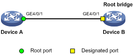
1. Network requirements
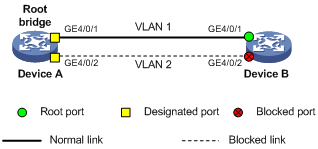
As shown in Figure 8:
¡ Device A and Device B are directly connected.
¡ GigabitEthernet 4/0/1 on Device A and GigabitEthernet 4/0/1 on Device B allow the traffic of VLAN 1 to pass through. GigabitEthernet 4/0/2 on Device A and GigabitEthernet 4/0/2 on Device B allow the traffic of VLAN 2 to pass through.
¡ Device A is the root bridge, and Device A and Device B both run a spanning tree protocol. GigabitEthernet 4/0/2 on Device B is blocked, causing traffic of VLAN 2 to be blocked.
Configure VLAN Ignore to keep GigabitEthernet 4/0/2 of Device B in the forwarding state.
2. Configuration procedure
# Enable VLAN Ignore for VLAN 2 on Device B.
<DeviceB> system-view
[DeviceB] stp ignored vlan 2
# Display the VLAN Ignore-enabled VLAN.
[DeviceB] display stp ignored-vlan
STP-Ignored VLAN: 2
Configuring Digest Snooping
As defined in IEEE 802.1s, interconnected devices are in the same region only when their MST region-related configurations (region name, revision level, and VLAN-to-instance mappings) are identical. A spanning tree device identifies devices in the same MST region by checking the configuration ID in BPDU packets. The configuration ID includes the region name, revision level, and configuration digest that is in 16-byte length and is the result calculated via the HMAC-MD5 algorithm based on VLAN-to-instance mappings.
Spanning tree implementations vary with vendors, and the configuration digests calculated using private keys is different, so devices of different vendors in the same MST region cannot communicate with each other.
To enable communication between an H3C device and a third-party device, enable the Digest Snooping feature on the port connecting the H3C device to the third-party device in the same MST region.
|
|
NOTE: Before enabling Digest Snooping, make sure that associated devices of different vendors are connected and run spanning tree protocols. |
Configuring the Digest Snooping feature
You can enable Digest Snooping only on the H3C device that is connected to a third-party device that uses its private key to calculate the configuration digest.
To configure Digest Snooping:
|
Step |
Command |
Remarks |
|
1. Enter system view. |
system-view |
N/A |
|
2. Enter interface view or port group view. |
·
Enter Ethernet interface view or Layer 2
aggregate interface view: ·
Enter port group view: |
Use either command. |
|
3. Enable Digest Snooping on the interface or port group. |
stp config-digest-snooping |
By default, Digest Snooping is disabled on a port. |
|
4. Return to system view. |
quit |
N/A |
|
5. Enable global Digest Snooping. |
stp config-digest-snooping |
By default, Digest Snooping is disabled globally. |
|
|
CAUTION: · With the Digest Snooping feature enabled, comparison of configuration digest is not needed for in-the-same-region check, so the VLAN-to-instance mappings must be the same on associated ports. · With global Digest Snooping enabled, modification of VLAN-to-instance mappings and removing of the current region configuration using the undo stp region-configuration command are not allowed. You can only modify the region name and revision level. · To make Digest Snooping take effect, you must enable Digest Snooping both globally and on associated ports. To make the configuration effective on all configured ports and while reducing impact on the network, enable Digest Snooping on all associated ports first and then globally. · To prevent loops, do not enable Digest Snooping on MST region edge ports. · H3C recommends you to enable Digest Snooping first and then the spanning tree feature. To avoid traffic interruption, do not configure Digest Snooping when the network is already working well. |
Digest Snooping configuration example
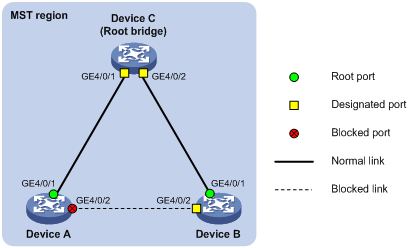
1. Network requirements
As shown in Figure 9, Device A and Device B connect to Device C, which is a third-party device. All these devices are in the same region.
Enable Digest Snooping on Device A’s and Device B’s ports that connect to Device C, so that the three devices can communicate with one another.
2. Configuration procedure
# Enable Digest Snooping on GigabitEthernet 4/0/1 of Device A and enable global Digest Snooping on Device A.
<DeviceA> system-view
[DeviceA] interface gigabitethernet 4/0/1
[DeviceA-GigabitEthernet4/0/1] stp config-digest-snooping
[DeviceA-GigabitEthernet4/0/1] quit
[DeviceA] stp config-digest-snooping
# Enable Digest Snooping on GigabitEthernet 4/0/1 of Device B and enable global Digest Snooping on Device B.
<DeviceB> system-view
[DeviceB] interface gigabitethernet 4/0/1
[DeviceB-GigabitEthernet4/0/1] stp config-digest-snooping
[DeviceB-GigabitEthernet4/0/1] quit
[DeviceB] stp config-digest-snooping
Configuring No Agreement Check
In RSTP and MSTP, the following types of messages are used for rapid state transition on designated ports:
· Proposal—Sent by designated ports to request rapid transition
· Agreement—Used to acknowledge rapid transition requests
Both RSTP and MSTP devices can perform rapid transition on a designated port only when the port receives an agreement packet from the downstream device. RSTP and MSTP devices have the following differences:
· For MSTP, the downstream device’s root port sends an agreement packet only after it receives an agreement packet from the upstream device.
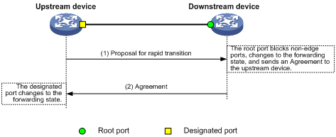
· For RSTP, the downstream device sends an agreement packet regardless of whether an agreement packet from the upstream device is received.
Figure 10 shows the rapid state transition mechanism on MSTP designated ports.
Figure 10 Rapid state transition of an MSTP designated port
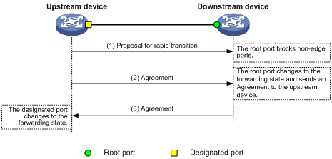
Figure 11 shows rapid state transition of an RSTP designated port.
Figure 11 Rapid state transition of an RSTP designated port
If the upstream device is a third-party device, the rapid state transition implementation may be limited. For example, when the upstream device uses a rapid transition mechanism similar to that of RSTP, and the downstream device adopts MSTP and does not work in RSTP mode, the root port on the downstream device receives no agreement packet from the upstream device and sends no agreement packets to the upstream device. As a result, the designated port of the upstream device fails to transit rapidly and can only change to the forwarding state after a period twice the Forward Delay.
You can enable the No Agreement Check feature on the downstream device’s port to enable the designated port of the upstream device to transit its state rapidly.
Configuration Prerequisites
Before you configure the No Agreement Check function, complete the following tasks:
· Connect a device to a third-party upstream device supporting spanning tree protocols via a point-to-point link.
· Configure the same region name, revision level and VLAN-to-instance mappings on the two devices, assigning them to the same region.
Configuring the No Agreement Check function
To make the No Agreement Check feature take effect, enable it on the root port.
To configure No Agreement Check:
|
Step |
Command |
Remarks |
|
1. Enter system view. |
system-view |
N/A |
|
2. Enter interface view or port group view. |
·
Enter Ethernet interface view or Layer 2
aggregate interface view: ·
Enter port group view: |
Use either command. |
|
3. Enable No Agreement Check. |
stp no-agreement-check |
By default, No Agreement Check is disabled. |
No Agreement Check configuration example
1. Network requirements
As shown in Figure 12:
¡ Device A connects to Device B, a third-party device that has a different spanning tree implementation. Both devices are in the same region.
¡ Device B is the regional root bridge, and Device A is the downstream device.
Figure 12 No Agreement Check configuration
2. Configuration procedure
# Enable No Agreement Check on GigabitEthernet 4/0/1 of Device A.
<DeviceA> system-view
[DeviceA] interface gigabitethernet 4/0/1
[DeviceA-GigabitEthernet4/0/1] stp no-agreement-check
Configuring TC snooping
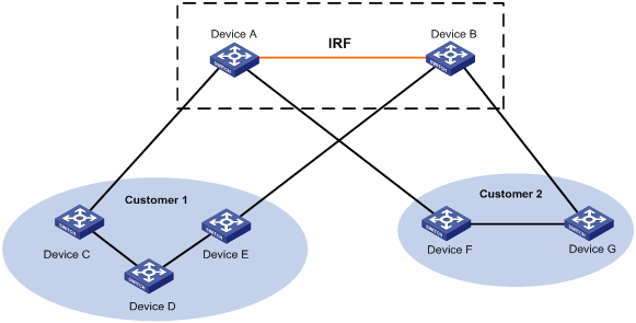
Figure 13 shows a topology change (TC) snooping application scenario. Device A and Device B are both IRF-enabled switches and form an IRF fabric; they operate at the distribution layer and do not have any spanning tree protocol enabled. The IRF fabric formed by Device A and Device B connect to multiple access-layer customer networks, such as Customer 1 and Customer 2. Device C, Device D, and Device E in customer network Customer 1 are all enabled with a spanning tree protocol. Customer 1 is dual-uplinked to the IRF fabric for high availability. The IRF fabric transparently transmits STP BPDUs from Customer 1 at Layer 2. Other customer networks (such as Customer 2) act the same as Customer 1.
Figure 13 TC snooping application scenario
In the network, the IRF fabric transparently transmits the received STP BPDUs and does not participate in STP calculations. When a topology change occurs to the IRF fabric or attached access-layer networks, the IRF fabric may need a long time to learn the correct MAC address table entries and ARP entries, resulting in long network disruption. To avoid the network disruption, you can enable TC snooping on the IRF fabric.
TC snooping enables the device to actively clear the MAC address table entries and ARP entries upon receiving TC-BPDUs and to re-learn the MAC address table entries and ARP entries, so that the device can normally forward the user traffic.
To configure TC snooping:
|
Step |
Command |
Description |
|
1. Enter system view. |
system-view |
N/A |
|
2. Globally disable the spanning tree feature. |
undo stp enable |
By default, the spanning tree feature is enabled globally. |
|
3. Enable TC snooping. |
stp tc-snooping |
By default, TC snooping is disabled. |
|
|
NOTE: · TC snooping is supported on Ethernet interface cards only. · TC snooping and the spanning tree feature are mutually exclusive. Globally disable the spanning tree feature before you enable TC snooping. · TC snooping is ineffective on the ports on which BPDU tunneling is enabled for STP. For more information about BPDU tunneling, see the chapter “Configuring BPDU tunneling.” |
Configuring protection functions
A spanning tree device supports the following protection functions:
· BPDU guard
· Root guard
· Loop guard
· TC-BPDU guard
Enabling BPDU guard
For access layer devices, the access ports can directly connect to the user terminals (such as PCs) or file servers. The access ports are configured as edge ports to allow rapid transition. When these ports receive configuration BPDUs, the system automatically sets the ports as non-edge ports and starts a new spanning tree calculation process. This causes a change of network topology. Under normal conditions, these ports should not receive configuration BPDUs. However, if someone forges configuration BPDUs maliciously to attack the devices, the network will become instable.
The spanning tree protocol provides the BPDU guard function to protect the system against such attacks. With the BPDU guard function enabled on the devices, when edge ports receive configuration BPDUs, the system will close these ports and notify the NMS that these ports have been closed by the spanning tree protocol. Ports disabled in this way will be re-activated by the device after a detection interval. For more information about this detection interval, see Fundamentals Configuration Guide.
Configure BPDU guard on a device with edge ports configured.
To enable BPDU guard:
|
Step |
Command |
Remarks |
|
1. Enter system view. |
system-view |
N/A |
|
2. Enable the BPDU guard function for the switch. |
stp bpdu-protection |
By default, BPDU guard is disabled. |
|
|
NOTE: BPDU guard does not take effect on loopback-testing-enabled ports. For more information about loopback testing, see Interface Configuration Guide. |
Enabling root guard
The root bridge and secondary root bridge of a spanning tree should be located in the same MST region. Especially for the CIST, the root bridge and secondary root bridge are put in a high-bandwidth core region during network design. However, due to possible configuration errors or malicious attacks in the network, the legal root bridge may receive a configuration BPDU with a higher priority. The current legal root bridge will be superseded by another device, causing an undesired change of the network topology. As a result, the traffic that should go over high-speed links is switched to low-speed links, resulting in network congestion.
To prevent this situation, MSTP provides the root guard function. If the root guard function is enabled on a port of a root bridge, this port plays the role of designated port on all MSTIs. Once this port receives a configuration BPDU with a higher priority from an MSTI, it immediately sets that port to the listening state in the MSTI, without forwarding the packet (this is equivalent to disconnecting the link connected with this port in the MSTI). If the port receives no BPDUs with a higher priority within twice the forwarding delay, it will revert to its original state.
Configure root guard on a designated port.
To enable root guard:
|
Step |
Command |
Remarks |
|
1. Enter system view. |
system-view |
N/A |
|
2. Enter interface view or port group view. |
·
Enter Ethernet interface view or Layer 2
aggregate interface view: ·
Enter port group view: |
Use either command. |
|
3. Enable the root guard function for the ports. |
stp root-protection |
By default, root guard is disabled. |
|
|
NOTE: On a port, the root guard function and the loop guard function are mutually exclusive. |
Enabling loop guard
A device that keeps receiving BPDUs from the upstream device can maintain the state of the root port and blocked ports. However, link congestion or unidirectional link failures may cause these ports to fail to receive BPDUs from the upstream devices. The device will reselect the port roles: Those ports in forwarding state that failed to receive upstream BPDUs will become designated ports, and the blocked ports will transition to the forwarding state, resulting in loops in the switched network. The loop guard function can suppress the occurrence of such loops.
The initial state of a loop guard-enabled port is discarding in every MSTI. When the port receives BPDUs, its state transitions normally. Otherwise, it stays in the discarding state to prevent temporary loops.
Configure loop guard on the root port and alternate ports of a device.
To enable loop guard:
|
Step |
Command |
Remarks |
|
1. Enter system view. |
system-view |
N/A |
|
2. Enter interface view or port group view. |
·
Enter Ethernet interface view or Layer 2 aggregate
interface view: ·
Enter port group view: |
Use either command. |
|
3. Enable the loop guard function for the ports. |
stp loop-protection |
By default, loop guard is disabled. |
|
|
NOTE: · Do not enable loop guard on a port connecting user terminals. Otherwise, the port will stay in the discarding state in all MSTIs because it cannot receive BPDUs. · On a port, the loop guard function is mutually exclusive with the edge port settings or the root guard function. |
Enabling TC-BPDU guard
When a switch receives topology change (TC) BPDUs, it flushes the forwarding address entries. If someone forges TC-BPDUs to attack the switch, the switch will receive a large number of TC-BPDUs within a short time and be busy with forwarding address entry flushing. This affects network stability.
With the TC-BPDU guard function, you can set the maximum number of immediate forwarding address entry flushes that the switch can perform every a certain period of time (10 seconds). For TC-BPDUs received in excess of the limit, the switch performs a forwarding address entry flush when the time period expires. This prevents frequent flushing of forwarding address entries.
To enable TC-BPDU guard:
|
Step |
Command |
Remarks |
|
1. Enter system view. |
system-view |
N/A |
|
2. Enable the TC-BPDU guard function. |
stp tc-protection enable |
Optional. By default, TC-BPDU guard is enabled. |
|
3. Configure the maximum number of forwarding address entry flushes that the switch can perform every 10 seconds. |
stp tc-protection threshold number |
Optional. The default setting is 6. |
|
|
NOTE: H3C does not recommend you disable this feature. |
Displaying and maintaining the spanning tree
|
Task |
Command |
Remarks |
|
Display information about ports blocked by spanning tree protection functions. |
display stp abnormal-port [ | { begin | exclude | include } regular-expression ] |
Available in any view |
|
Display BPDU statistics on ports. |
display stp bpdu-statistics [ interface interface-type interface-number [ instance instance-id ] ] [ | { begin | exclude | include } regular-expression ] |
Available in any view |
|
Display information about ports shut down by spanning tree protection functions. |
display stp down-port [ | { begin | exclude | include } regular-expression ] |
Available in any view |
|
Display the historical information of port role calculation for the specified MSTI or all MSTIs (in standalone mode). |
display stp [ instance instance-id ] history [ slot slot-number ] [ | { begin | exclude | include } regular-expression ] |
Available in any view |
|
Display the historical information of port role calculation for the specified MSTI or all MSTIs (in IRF mode). |
display stp [ instance instance-id ] history [ chassis chassis-number slot slot-number ] [ | { begin | exclude | include } regular-expression ] |
Available in any view |
|
Display the statistics of TC/TCN BPDUs sent and received by all ports in the specified MSTI or all MSTIs (in standalone mode). |
display stp [ instance instance-id ] tc [ slot slot-number ] [ | { begin | exclude | include } regular-expression ] |
Available in any view |
|
Display the statistics of TC/TCN BPDUs sent and received by all ports in the specified MSTI or all MSTIs (in IRF mode). |
display stp [ instance instance-id ] tc [ chassis chassis-number slot slot-number ] [ | { begin | exclude | include } regular-expression ] |
Available in any view |
|
Display the spanning tree status and statistics (in standalone mode). |
display stp [ instance instance-id ] [ interface interface-list | slot slot-number ] [ brief ] [ | { begin | exclude | include } regular-expression ] |
Available in any view |
|
Display the spanning tree status and statistics (in IRF mode). |
display stp [ instance instance-id ] [ interface interface-list | chassis chassis-number slot slot-number ] [ brief ] [ | { begin | exclude | include } regular-expression ] |
Available in any view |
|
Display the MST region configuration information that has taken effect. |
display stp region-configuration [ | { begin | exclude | include } regular-expression ] |
Available in any view |
|
Display the root bridge information of all MSTIs. |
display stp root [ | { begin | exclude | include } regular-expression ] |
Available in any view |
|
Display the list of VLANs with VLAN Ignore enabled. |
display stp ignored-vlan [ | { begin | exclude | include } regular-expression ] |
Available in any view |
|
Clear the spanning tree statistics. |
reset stp [ interface interface-list ] |
Available in user view |
Spanning tree configuration examples
MSTP configuration example
Network requirements
As shown in Figure 14:
· All devices on the network are in the same MST region. Device A and Device B work at the distribution layer. Device C and Device D work at the access layer.
· Configure MSTP so that packets of different VLANs are forwarded along different spanning trees: Packets of VLAN 10 are forwarded along MSTI 1, those of VLAN 30 are forwarded along MSTI 3, those of VLAN 40 are forwarded along MSTI 4, and those of VLAN 20 are forwarded along MSTI 0.
· VLAN 10 and VLAN 30 are terminated on the distribution layer devices, and VLAN 40 is terminated on the access layer devices, so the root bridges of MSTI 1 and MSTI 3 are Device A and Device B respectively, and the root bridge of MSTI 4 is Device C.
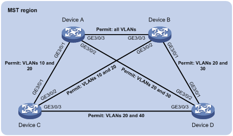
Configuration procedure
1. Configure VLANs and VLAN member ports (Details not shown)
Create VLAN 10, VLAN 20, and VLAN 30 on Device A and Device B respectively, VLAN 10, VLAN 20, and VLAN 40 on Device C, and VLAN 20, VLAN 30, and VLAN 40 on Device D. Configure the ports on these devices as trunk ports and assign them to related VLANs.
2. Configure Device A.
# Enter MST region view, configure the MST region name as example, map VLAN 10, VLAN 30, and VLAN 40 to MSTI 1, MSTI 3, and MSTI 4 respectively, and configure the revision level of the MST region as 0.
<DeviceA> system-view
[DeviceA] stp region-configuration
[DeviceA-mst-region] region-name example
[DeviceA-mst-region] instance 1 vlan 10
[DeviceA-mst-region] instance 3 vlan 30
[DeviceA-mst-region] instance 4 vlan 40
[DeviceA-mst-region] revision-level 0
# Activate MST region configuration.
[DeviceA-mst-region] active region-configuration
[DeviceA-mst-region] quit
# Specify the current device as the root bridge of MSTI 1.
[DeviceA] stp instance 1 root primary
# Enable the spanning tree feature globally.
[DeviceA] stp enable
3. Configure Device B.
# Enter MST region view, configure the MST region name as example, map VLAN 10, VLAN 30, and VLAN 40 to MSTI 1, MSTI 3, and MSTI 4 respectively, and configure the revision level of the MST region as 0.
<DeviceB> system-view
[DeviceB] stp region-configuration
[DeviceB-mst-region] region-name example
[DeviceB-mst-region] instance 1 vlan 10
[DeviceB-mst-region] instance 3 vlan 30
[DeviceB-mst-region] instance 4 vlan 40
[DeviceB-mst-region] revision-level 0
# Activate MST region configuration.
[DeviceB-mst-region] active region-configuration
[DeviceB-mst-region] quit
# Specify the current device as the root bridge of MSTI 3.
[DeviceB] stp instance 3 root primary
# Enable the spanning tree feature globally.
[DeviceB] stp enable
4. Configure Device C.
# Enter MST region view, configure the MST region name as example, map VLAN 10, VLAN 30, and VLAN 40 to MSTI 1, MSTI 3, and MSTI 4 respectively, and configure the revision level of the MST region as 0.
<DeviceC> system-view
[DeviceC] stp region-configuration
[DeviceC-mst-region] region-name example
[DeviceC-mst-region] instance 1 vlan 10
[DeviceC-mst-region] instance 3 vlan 30
[DeviceC-mst-region] instance 4 vlan 40
[DeviceC-mst-region] revision-level 0
# Activate MST region configuration.
[DeviceC-mst-region] active region-configuration
[DeviceC-mst-region] quit
# Specify the current device as the root bridge of MSTI 4.
[DeviceC] stp instance 4 root primary
# Enable the spanning tree feature globally.
[DeviceC] stp enable
5. Configure Device D.
# Enter MST region view, configure the MST region name as example, map VLAN 10, VLAN 30, and VLAN 40 to MSTI 1, MSTI 3, and MSTI 4 respectively, and configure the revision level of the MST region as 0.
<DeviceD> system-view
[DeviceD] stp region-configuration
[DeviceD-mst-region] region-name example
[DeviceD-mst-region] instance 1 vlan 10
[DeviceD-mst-region] instance 3 vlan 30
[DeviceD-mst-region] instance 4 vlan 40
[DeviceD-mst-region] revision-level 0
# Activate MST region configuration.
[DeviceD-mst-region] active region-configuration
[DeviceD-mst-region] quit
# Enable the spanning tree feature globally.
[DeviceD] stp enable
6. Verify the configuration.
You can use the display stp brief command to display brief spanning tree information on each device after the network is stable.
# Display brief spanning tree information on Device A.
[DeviceA] display stp brief
MSTID Port Role STP State Protection
0 GigabitEthernet3/0/1 ALTE DISCARDING NONE
0 GigabitEthernet3/0/2 DESI FORWARDING NONE
0 GigabitEthernet3/0/3 ROOT FORWARDING NONE
1 GigabitEthernet3/0/1 DESI FORWARDING NONE
1 GigabitEthernet3/0/3 DESI FORWARDING NONE
3 GigabitEthernet3/0/2 DESI FORWARDING NONE
3 GigabitEthernet3/0/3 ROOT FORWARDING NONE
# Display brief spanning tree information on Device B.
[DeviceB] display stp brief
MSTID Port Role STP State Protection
0 GigabitEthernet3/0/1 DESI FORWARDING NONE
0 GigabitEthernet3/0/2 DESI FORWARDING NONE
0 GigabitEthernet3/0/3 DESI FORWARDING NONE
1 GigabitEthernet3/0/2 DESI FORWARDING NONE
1 GigabitEthernet3/0/3 ROOT FORWARDING NONE
3 GigabitEthernet3/0/1 DESI FORWARDING NONE
3 GigabitEthernet3/0/3 DESI FORWARDING NONE
# Display brief spanning tree information on Device C.
[DeviceC] display stp brief
MSTID Port Role STP State Protection
0 GigabitEthernet3/0/1 DESI FORWARDING NONE
0 GigabitEthernet3/0/2 ROOT FORWARDING NONE
0 GigabitEthernet3/0/3 DESI FORWARDING NONE
1 GigabitEthernet3/0/1 ROOT FORWARDING NONE
1 GigabitEthernet3/0/2 ALTE DISCARDING NONE
4 GigabitEthernet3/0/3 DESI FORWARDING NONE
# Display brief spanning tree information on Device D.
[DeviceD] display stp brief
MSTID Port Role STP State Protection
0 GigabitEthernet3/0/1 ROOT FORWARDING NONE
0 GigabitEthernet3/0/2 ALTE DISCARDING NONE
0 GigabitEthernet3/0/3 ALTE DISCARDING NONE
3 GigabitEthernet3/0/1 ROOT FORWARDING NONE
3 GigabitEthernet3/0/2 ALTE DISCARDING NONE
4 GigabitEthernet3/0/3 ROOT FORWARDING NONE
Based on the output, you can draw the MSTI mapped to each VLAN, as shown in Figure 15.
Figure 15 MSTIs mapped to different VLANs
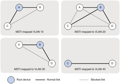
PVST configuration example
Network requirements
As shown in Figure 16, Device A and Device B work at the distribution layer. Device C and Device D work at the access layer.
Configure PVST so that packets of different VLANs are forwarded along different spanning trees.
VLAN 10, VLAN 20, and VLAN 30 are terminated on the distribution layer devices, and VLAN 40 is terminated on the access layer devices. The root bridge of VLAN 10 and VLAN 20 is Device A, that of VLAN 30 is Device B, and that of VLAN 40 is Device C.
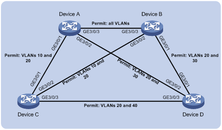
Configuration procedure
1. Configure VLANs and VLAN member ports. (Details not shown)
Create VLAN 10, VLAN 20, and VLAN 30 on Device A and Device B respectively, VLAN 10, VLAN 20, and VLAN 40 on Device C, and VLAN 20, VLAN 30, and VLAN 40 on Device D. Configure the ports on these devices as trunk ports and assign them to related VLANs.
2. Configure Device A.
# Set the spanning tree mode to PVST.
<DeviceA> system-view
[DeviceA] stp mode pvst
# Specify the device as the root bridge of VLAN 10 and VLAN 20.
[DeviceA] stp vlan 10 20 root primary
# Enable the spanning tree feature globally, and enable the spanning tree feature for VLANs 10, 20, and 30.
[DeviceA] stp enable
[DeviceA] stp vlan 10 20 30 enable
3. Configure Device B.
# Set the spanning tree mode to PVST.
<DeviceB> system-view
[DeviceB] stp mode pvst
# Specify the device as the root bridge of VLAN 30.
[DeviceB] stp vlan 30 root primary
# Enable the spanning tree feature globally, and enable the spanning tree feature for VLANs 10, 20, and 30.
[DeviceA] stp enable
[DeviceA] stp vlan 10 20 30 enable
4. Configure Device C.
# Set the spanning tree mode to PVST.
<DeviceC> system-view
[DeviceC] stp mode pvst
# Specify the current device as the root bridge of VLAN 40.
[DeviceC] stp vlan 40 root primary
# Enable the spanning tree feature globally, and enable the spanning tree feature for VLANs 10, 20, and 40.
[DeviceA] stp enable
[DeviceA] stp vlan 10 20 40 enable
5. Configure Device D.
# Set the spanning tree mode to PVST.
<DeviceD> system-view
[DeviceD] stp mode pvst
# Enable the spanning tree feature globally, and enable the spanning tree feature for VLANs 20, 30, and 40.
[DeviceA] stp enable
[DeviceA] stp vlan 20 30 40 enable
6. Verify the configuration.
You can use the display stp brief command to display brief spanning tree information on each device after the network is stable.
[DeviceA] display stp brief
VLAN Port Role STP State Protection
10 GigabitEthernet3/0/1 DESI DISCARDING NONE
10 GigabitEthernet3/0/3 DESI FORWARDING NONE
20 GigabitEthernet3/0/1 DESI FORWARDING NONE
20 GigabitEthernet3/0/2 DESI FORWARDING NONE
20 GigabitEthernet3/0/3 DESI FORWARDING NONE
30 GigabitEthernet3/0/2 DESI FORWARDING NONE
30 GigabitEthernet3/0/3 ROOT FORWARDING NONE
# Display brief spanning tree information on Device B.
[DeviceB] display stp brief
VLAN Port Role STP State Protection
10 GigabitEthernet3/0/2 DESI FORWARDING NONE
10 GigabitEthernet3/0/3 ROOT FORWARDING NONE
20 GigabitEthernet3/0/1 DESI FORWARDING NONE
20 GigabitEthernet3/0/2 DESI FORWARDING NONE
20 GigabitEthernet3/0/3 ROOT FORWARDING NONE
30 GigabitEthernet3/0/1 DESI FORWARDING NONE
30 GigabitEthernet3/0/3 DESI FORWARDING NONE
# Display brief spanning tree information on Device C.
[DeviceC] display stp brief
VLAN Port Role STP State Protection
10 GigabitEthernet3/0/1 ROOT FORWARDING NONE
10 GigabitEthernet3/0/2 ALTE FORWARDING NONE
20 GigabitEthernet3/0/1 ROOT FORWARDING NONE
20 GigabitEthernet3/0/2 ALTE FORWARDING NONE
20 GigabitEthernet3/0/3 DESI DISCARDING NONE
40 GigabitEthernet3/0/3 DESI FORWARDING NONE
# Display brief spanning tree information on Device D.
[DeviceD] display stp brief
VLAN Port Role STP State Protection
20 GigabitEthernet3/0/1 ALTE FORWARDING NONE
20 GigabitEthernet3/0/2 ROOT DISCARDING NONE
20 GigabitEthernet3/0/3 ALTE DISCARDING NONE
30 GigabitEthernet3/0/1 ROOT FORWARDING NONE
30 GigabitEthernet3/0/2 ALTE DISCARDING NONE
40 GigabitEthernet3/0/3 ROOT FORWARDING NONE
Based on the output, you can draw the spanning tree mapped to each VLAN, as shown in Figure 17.
Figure 17 Spanning trees mapped to different VLANs