| Title | Size | Downloads |
|---|---|---|
| H3C S9500E Routing Switch Series Installation Guide-6PW107-Chapter 1 Product Overview .pdf | 2.69 MB |
- Table of Contents
- Related Documents
-
| Title | Size | Download |
|---|---|---|
| 01-Chapter 1 Product Overview | 2.69 MB |
The H3C S9500E switches include the models in Table 1.
|
Model |
Power supply |
Slot orientation |
Main processing unit (MPU) slots |
Line processing unit (LPU) slots |
|
S9505E |
AC/DC |
Horizontal |
2 |
5 |
|
S9508E |
AC/DC |
Horizontal |
2 |
8 |
|
S9508E-V |
AC/DC |
Vertical |
2 |
8 |
|
S9512E |
AC/DC |
Horizontal |
2 |
12 |
Physical architecture
An H3C S9500E chassis comprises a backplane, power supply system, fan system, and card cage.
|
|
NOTE: The diagrams in this guide are for illustration only, and AC-powered chassis are used for example. |
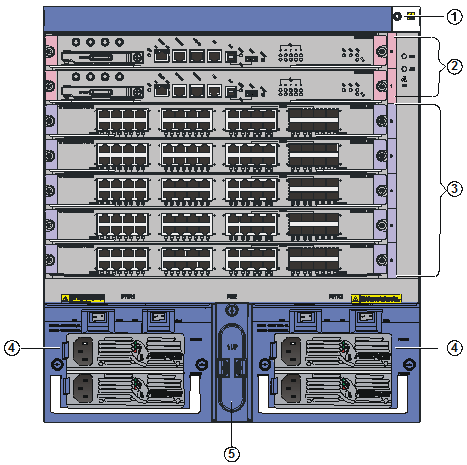
S9505E chassis views
|
(1) ESD-preventive wrist strap port |
(2) MPU slots (slots 0 and 1) |
(3) LPU slots (slots 2 through 6) |
|
(4) AC power supplies |
(5) PoE power entry module (reserved, currently unavailable) |
|
|
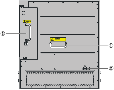
(1) Rear cover handle |
(2) Grounding screw |
(3) Fan tray |
The S9505E chassis has the following slots and components:
· Two MPU slots, five LPU slots, and two power supply slots at the front.
· One vertically oriented, hot swappable fan tray at the rear. The fans draw air in from the left side and exhaust air out of the right side. For the ventilation direction inside the chassis, see "Preparing for installation."
|
|
NOTE: Intermixing of AC and DC power supplies is not allowed. |
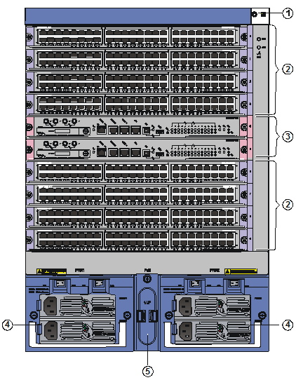
S9508E chassis views
Figure 3 S9508E front view
|
(1) ESD-preventive wrist strap port |
(2) LPU slots (slots 0 through 3, and 6 through 9) |
|
(3) MPU slots (slots 4 and 5) |
(4) AC power supplies |
|
(5) PoE power entry module (reserved, currently not available) |
|
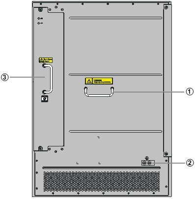
Figure 4 S9508E rear view
|
(1) Rear cover handle |
(2) Grounding screw |
(3) Fan tray |
The S9508E chassis has the following slots and components:
· Two MPU slots, eight LPU slots, and two power supply slots at the front.
· One vertically oriented, hot swappable fan tray at the rear. The fans draw air in from the left side and exhaust air out of the right side. For the ventilation direction inside the chassis, see "Preparing for installation."
|
|
NOTE: Intermixing of AC and DC power supplies is not allowed. |
S9508E-V chassis views
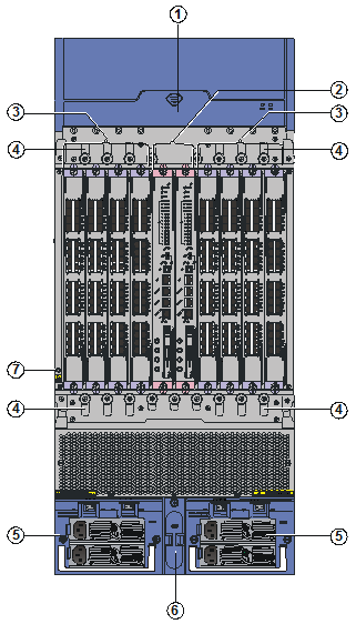
|
(1) Fan tray |
(2) MPU slots (slots 4 and 5) |
(3) LPU slots (slots 0 to 3, 6 to 9) |
|
(4) Cable management bracket |
(5) AC power supplies |
|
|
(6) PoE power entry module (reserved, currently not available) |
||
|
(7) ESD-preventive wrist strap port |
||
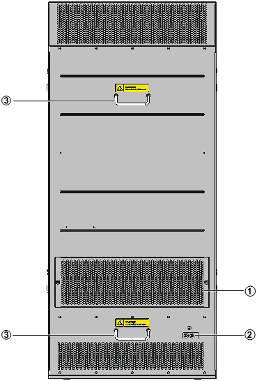
|
(1) Ventilation panel |
(2) Grounding screw |
(3) Rear cover handles |
The S9508E-V chassis has the following slots and components:
· Two MPU slots, eight LPU slots, and two power supply slots at the front. Both MPU and LPU slots are vertically oriented.
· One horizontally oriented, hot swappable fan tray at the front. The fans draw air in from the front and rear of the bottom of the chassis and exhaust air out of the left and right sides and rear at the top of the chassis. For the ventilation direction inside the chassis, see "Preparing for installation."
|
|
NOTE: Intermixing of AC and DC power supplies is not allowed. |
S9512E chassis views
Figure 7 S9512E front view
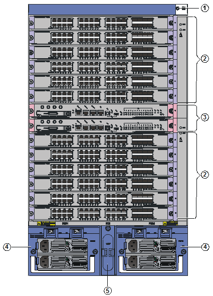
|
(1) ESD-preventive strap port |
(2) LPU slots (slots 0 to 5, 8 to 13) |
(3) MPU slots (slots 6 and 7) |
|
(4) AC power supplies |
(5) PoE power entry module (reserved, currently not available) |
|
Figure 8 S9512E rear view
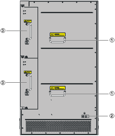
|
(1) Rear cover handle |
(2) Grounding screw |
(3) Fan tray and handle |
The S9512E chassis has the following slots and components:
· Two MPU slots, 12 LPU slots, and two power supply slots at the front.
· Two vertically oriented, hot swappable fan trays at the rear. The fans draw air in from the left side and exhaust air out of the right side. For the ventilation direction inside the chassis, see "Preparing for installation."
|
|
NOTE: Intermixing of AC and DC power supplies is not allowed. |
Backplane
· Provides communication channels for signal exchange between cards.
· Supports hot-swapping of cards.
· Connects to the power frame, implements distributed power supply for MPUs, LPUs, switching fabric modules, fan trays and power supplies, and provides monitoring channels for MPUs to monitor power frame status.
Power supply system
The S9500E switches support both AC and DC power supply. If two power supplies are used, make sure they are the same type.
AC power supply
Each AC power supply comprises a power frame, and depending on your configuration, one or two sub power supplies installed in the power frame. The S9500E switches use the NEPS3500-A power frame and the NEPS1800-A sub power supplies.
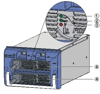
Figure 9 AC power supply
|
(1) Power input LED |
(2) Power output LED |
(3) Power fault LED |
(4) Sub power supplies |
Table 2 AC sub power supply specifications
|
Item |
Description |
|
Rated input voltage range |
100 VAC to 120 VAC/200 VAC to 240 VAC @ 50 Hz or 60 Hz |
|
Max input voltage range |
90 VAC to 264 VAC @ 50 Hz or 60 Hz |
|
Max input current |
20 A |
|
Max output power |
1800 W @ 200 VAC to 240 VAC input 1200 W @ 100 VAC to 120 VAC input |
|
|
NOTE: If two NEPS1800-A sub power supplies are used, the maximum output power of the NEPS3500-A power supply is 3500 W. |
Table 3 AC power supply LED description
|
LED |
Status |
Description |
|
Input |
Steady on |
Power is being correctly input. |
|
Off |
The power supply is absent or has input voltage error. |
|
|
Output |
Steady on |
The power supply is correctly outputting power. |
|
Off |
The power supply has output voltage error or is absent. |
|
|
Fault |
Steady on |
The power supply is experiencing an overvoltage, overcurrent, or over-temperature condition. |
|
Off |
The power supply is operating properly or absent. |
DC power supply
The S9500E switches support two DC power supply models: NEPS2000-D and NEPS3500-D.
Table 4 DC power supply specifications
|
Item |
Description |
|
|
NEPS2000-D |
NEPS3500-D |
|
|
Rated input voltage range |
–48 VDC to –60 VDC |
–48 VDC to –60 VDC |
|
Max input voltage range |
–40 VDC to –72 VDC |
–40 VDC to –72 VDC |
|
Max input current |
60 A |
80 A |
|
Max output power |
2000 W |
3500 W |
|
|
NOTE: When the max input voltage of the NEPS3500-D is –40 VDC, the max output power is 3200 W. |
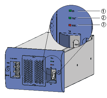
Figure 10 NEPS2000-D DC power supply
|
(1) Power input LED |
(2) Power output LED |
(3) Power fault LED |
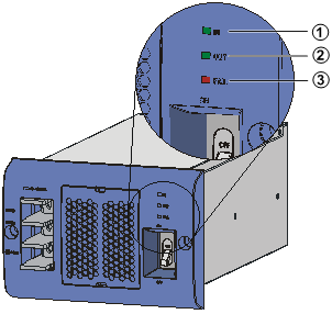
Figure 11 NEPS3500-D DC power supply
|
(1) Power input LED |
(2) Power output LED |
(3) Power fault LED |
Table 5 DC power supply LED description
|
LED |
Status |
Description |
|
IN (input) |
Steady on |
Power is being correctly input. |
|
Off |
The power supply is absent or has input voltage error. |
|
|
OUT (output) |
Steady on |
The power supply is correctly outputting power. |
|
Off |
The power supply has output voltage error or is absent. |
|
|
FAIL (fault) |
Steady on |
The power supply is experiencing an overvoltage, overcurrent, or over-temperature condition. |
|
Off |
The power supply is operating properly or absent. |
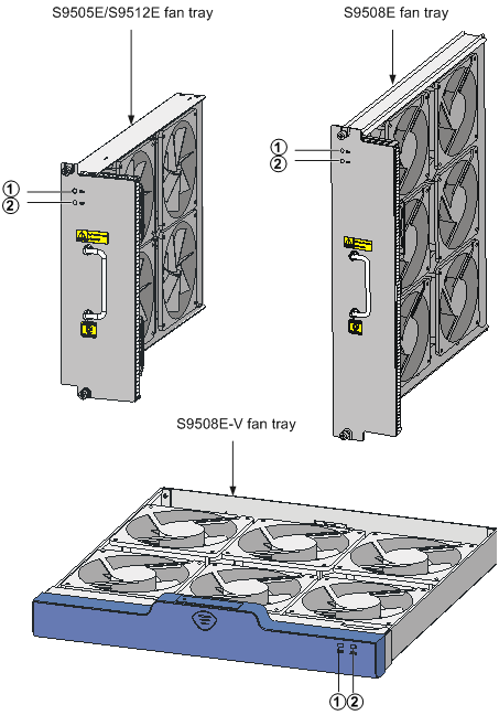
Fan tray
S9500E fan trays provide the following functions:
· Effective heat dissipation ensures long time operation of the switch.
· Status monitoring, including fan rotation speed monitoring and fault alarming.
· Automatic speed adjustment decreases noise and improves energy efficiency.
· Each fan tray has two LEDs on the front panel to show its operating status.
· The fan trays are hot swappable, and you can replace fan trays without powering off the switch.
|
|
IMPORTANT: The S9505E and the S9512E use the same type of fan trays. The S9508E and the S9508E-V have chassis-specific fan trays and cannot use the fan trays for any other S9500E switch models. |
|
(1) RUN LEDs |
(2) ALM LEDs |
|
LED |
Status |
Description |
|
RUN |
Off |
The fan tray has failed. |
|
Steady on |
The fan tray is operating properly. |
|
|
ALM |
Off |
The fan tray is in normal state. |
|
Steady on |
The fan tray is faulty. |
