- Table of Contents
- Related Documents
-
| Title | Size | Download |
|---|---|---|
| 02-IP Routing Basics Configuration | 76.62 KB |
Table of Contents
1 IP Routing Basics Configuration
Routing Protocols and Routing Preference
Displaying and Maintaining a Routing Table
l The models listed in this document are not applicable to all regions. Please consult your local sales office for the models applicable to your region.
l Support of the H3C WA series WLAN access points (APs) for features may vary by AP model. For more information, see Feature Matrix.
l The interface types and the number of interfaces vary by AP model.
l The term AP in this document refers to common APs, wireless bridges, and mesh APs.
1 IP Routing Basics Configuration
This chapter includes these sections:
l IP Routing and Routing Table
l Displaying and Maintaining a Routing Table
![]()
l The term router in this document refers to both routers and APs configured with routing capabilities.
l Support for IPv6 depends on the AP model.
IP Routing and Routing Table
Routing
Routing in the Internet is achieved through routers. Upon receiving a packet, a router finds an optimal route based on the destination address and forwards the packet to the next router in the path until the packet reaches the last router, which forwards the packet to the intended destination host.
Routing Table
Routing table
Routing tables play a key role in routing. Each router maintains a routing table, and each entry in the table specifies which physical interface a packet destined for a certain destination should go out to reach the next hop (the next router) or the directly connected destination.
Routes in a routing table can be divided into three categories by origin:
l Direct routes: Routes discovered by data link protocols, also known as interface routes.
l Static routes: Routes that are manually configured.
l Dynamic routes: Routes that are discovered dynamically by routing protocols.
Contents of a routing table
A routing table includes the following key items:
l Destination address: Destination IP address or destination network.
l Network mask: Specifies, in company with the destination address, the address of the destination network. A logical AND operation between the destination address and the network mask yields the address of the destination network. For example, if the destination address is 129.102.8.10 and the mask 255.255.0.0, the address of the destination network is 129.102.0.0. A network mask is made up of a certain number of consecutive 1s. It can be expressed in dotted decimal format or by the number of 1s.
l Outbound interface: Specifies the interface through which the IP packets are to be forwarded.
l Next hop: Specifies the IP address of the next-hop router on the path. If only the outbound interface is configured, its address will be the IP address of the next hop.
l Preference for the route. Routes to the same destination but having different next hops may have different priorities and be found by various routing protocols or manually configured. The optimal route is the one with the highest preference (with the smallest metric).
Routes can be divided into two categories by destination:
l Subnet routes: The destination is a subnet.
l Host routes: The destination is a host.
Based on whether the destination is directly connected to a given router, routes can be divided into:
l Direct routes: The destination is directly connected to the router.
l Indirect routes: The destination is not directly connected to the router.
To prevent the routing table from getting too large, you can configure a default route. Packets not matching any specific entries in the routing table will be forwarded through the default route.
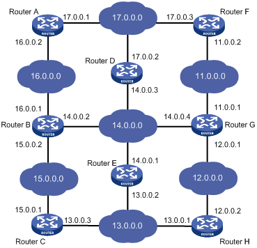
In Figure 1-1, Router G is connected to three networks. Its routing table is shown under the network topology.
Figure 1-1 A sample routing table
|
Destination network |
Next hop |
Interface |
|
11.0.0.0 |
11.0.0.1 |
2 |
|
12.0.0.0 |
12.0.0.1 |
1 |
|
13.0.0.0 |
12.0.0.2 |
1 |
|
14.0.0.0 |
14.0.0.4 |
3 |
|
15.0.0.0 |
14.0.0.2 |
3 |
|
16.0.0.0 |
14.0.0.2 |
3 |
|
17.0.0.0 |
11.0.0.2 |
2 |
Routing Protocol Overview
Static Routing
Static routing is easy to configure and requires less system resources. It works well in small, stable networks with simple topologies. Its major drawback is that you need to perform routing configuration again whenever the network topology changes; it cannot adapt to network changes by itself.
Routing Protocols and Routing Preference
The following table lists some routing protocols and the default preferences for routes found by them:
|
Routing approach |
Preference |
|
DIRECT |
0 |
|
STATIC |
60 |
|
UNKNOWN |
256 |
l The smaller the preference value, the higher the preference.
l The preference for a direct route is always 0, which you cannot change. Any other type of routes can have their preferences manually configured.
l Each static route can be configured with a different preference.
l IPv4 and IPv6 routes have their own respective routing tables.
Route Backup
Route backup can help improve network reliability. With route backup, you can configure multiple routes to the same destination, expecting the one with the highest preference to be the main route and all the rest backup routes.
Under normal circumstances, packets are forwarded through the main route. When the main route goes down, the route with the highest preference among the backup routes is selected to forward packets. When the main route recovers, the route selection process is performed again and the main route is selected again to forward packets.
Route Redistribution
Different routing protocols running on a network learn route information from each other through route redistribution. Each routing protocol has its own route redistribution mechanism.
Displaying and Maintaining a Routing Table
|
To do… |
Use the command… |
Remarks |
|
Display brief information about the active routes in the routing table |
display ip routing-table [ verbose ] |
Available in any view |
|
Display brief IPv6 routing table information |
display ipv6 routing-table |
Available in any view |
|
Display verbose IPv6 routing table information |
display ipv6 routing-table verbose |
Available in any view |