- Table of Contents
- Related Documents
-
| Title | Size | Download |
|---|---|---|
| 06-VLAN Configuration | 131.11 KB |
Configuring Basic VLAN Settings
Configuring Basic Settings of a VLAN Interface
Introduction to Port-Based VLAN
Assigning an Access Port to a VLAN
Assigning a Trunk Port to a VLAN
Assigning a Hybrid Port to a VLAN
Introduction to MAC-Based VLAN
Configuring a MAC Address-Based VLAN
Displaying and Maintaining VLAN
l The models listed in this document are not applicable to all regions. Please consult your local sales office for the models applicable to your region.
l Support of the H3C WA series WLAN access points (APs) for features may vary by AP model. For more information, see Feature Matrix.
l The interface types and the number of interfaces vary by AP model.
l The term AP in this document refers to common APs, wireless bridges, and mesh APs.
This chapter includes these sections:
l Configuring Basic VLAN Settings
l Configuring Basic Settings of a VLAN Interface
l Port-Based VLAN Configuration
l MAC-Based VLAN Configuration
Introduction to VLAN
VLAN Overview
Ethernet is a network technology based on the Carrier Sense Multiple Access/Collision Detect (CSMA/CD) mechanism. As the medium is shared, collisions and excessive broadcasts cannot be avoided on an Ethernet. To address the issue, virtual LAN (VLAN) was introduced.
The idea is to break a LAN down into separate VLANs, that is, Layer 2 broadcast domains whereby frames are switched between ports assigned to the same VLAN. VLANs are isolated from each other at Layer 2. A VLAN is a bridging domain, and all broadcast traffic is contained within it, as shown in Figure 1-1.

A VLAN is logically divided on an organizational basis rather than on a physical basis. For example, all workstations and servers used by a particular workgroup can be connected to the same LAN, regardless of their physical locations.
VLAN technology delivers the following benefits:
1) Confining broadcast traffic within individual VLANs. This reduces bandwidth waste and improves network performance.
2) Improving LAN security. By assigning user groups to different VLANs, you can isolate them at Layer 2. To enable communication between VLANs, routers or Layer 3 switches are required.
3) Flexible virtual workgroup creation. As users from the same workgroup can be assigned to the same VLAN regardless of their physical locations, network construction and maintenance is much easier and more flexible.
VLAN Fundamentals
To enable a network device to identify frames of different VLANs, a VLAN tag field is inserted into the data link layer encapsulation.
The format of VLAN-tagged frames is defined in IEEE 802.1Q issued by the Institute of Electrical and Electronics Engineers (IEEE) in 1999.
In the header of a traditional Ethernet data frame, the field after the destination MAC address and the source MAC address is the Type field indicating the upper layer protocol type, as shown in Figure 1-2.
Figure 1-2 The format of a traditional Ethernet frame
![]()
IEEE 802.1Q inserts a four-byte VLAN tag after the DA&SA field, as shown in Figure 1-3.
Figure 1-3 The position and format of VLAN tag
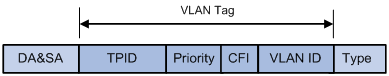
A VLAN tag comprises four fields: tag protocol identifier (TPID), priority, canonical format indicator (CFI), and VLAN ID.
l The 16-bit TPID field with a default value of 0x8100 indicates that the frame is VLAN-tagged.
l The 3-bit priority field indicates the 802.1p priority of the frame. For more information about frame priority, see QoS in the ACL and QoS Configuration Guide.
l The 1-bit CFI field specifies whether the MAC addresses are encapsulated in the standard format when packets are transmitted across different media. Value 0 indicates that MAC addresses are encapsulated in the standard format; value 1 indicates that MAC addresses are encapsulated in a non-standard format. The filed is 0 by default.
l The 12-bit VLAN ID field identifies the VLAN the frame belongs to. The VLAN ID range is 0 to 4095. As 0 and 4095 are reserved by the protocol, a VLAN ID actually ranges from 1 to 4094.
When receiving a frame, a network device looks at its VLAN tag to decide how to handle the frame.
![]()
l The Ethernet II encapsulation format is used here. Besides the Ethernet II encapsulation format, other encapsulation formats, including 802.2 LLC and 802.3 raw, are also supported by Ethernet. The VLAN tag fields are also added to frames encapsulated in these formats for VLAN identification.
l A network device transmits a frame carrying multiple VLAN tags according to its outermost VLAN tag, and transmits the inner VLAN tags of the frame as payload.
Types of VLAN
Currently, the AP supports port-based and MAC-based VLANs.
Configuring Basic VLAN Settings
Follow these steps to configure basic VLAN settings:
|
To do… |
Use the command… |
Remarks |
|
Enter system view |
system-view |
— |
|
Create VLANs |
vlan { vlan-id1 [ to vlan-id2 ] } |
Optional Using this command can create multiple VLANs in bulk. |
|
Enter VLAN view |
vlan vlan-id |
Required If the specified VLAN does not exist, this command creates the VLAN first. By default, only the default VLAN (that is, VLAN 1) exists in the system. |
|
Configure a name for the current VLAN |
name text |
Optional By default, the name of a VLAN is its VLAN ID, VLAN 0001 for example. |
|
Configure the description of the current VLAN |
description text |
Optional VLAN ID is used by default, for example, VLAN 0001. |
![]()
l As the default VLAN, VLAN 1 cannot be created or removed.
l Dynamic VLANs cannot be removed with the undo vlan command.
Configuring Basic Settings of a VLAN Interface
For hosts of different VLANs to communicate, you must use a router or Layer 3 switch to perform layer 3 forwarding. To achieve this, VLAN interfaces are used.
VLAN interfaces are virtual interfaces used for Layer 3 communication between different VLANs. They do not exist as physical entities on network devices. For each VLAN, you can create one VLAN interface. After you assign an IP address to this VLAN interface, it can serve as the gateway of devices in the VLAN to forward traffic destined for an IP network segment different from that of the VLAN.
Follow these steps to configure basic settings of a VLAN interface:
|
To do… |
Use the command… |
Remarks |
|
Enter system view |
system-view |
— |
|
Create a VLAN interface and enter VLAN interface view |
interface vlan-interface vlan-interface-id |
Required If the VLAN interface already exists, you enter its view directly. |
|
Assign an IP address to the VLAN interface |
ip address ip-address { mask | mask-length } |
Optional No IP address is assigned to any VLAN interface by default. |
|
Configure the description of the VLAN interface |
description text |
Optional VLAN interface name is used by default, for example, Vlan-interface1 Interface. |
|
Bring up the VLAN interface |
undo shutdown |
Optional By default, a VLAN interface is in the up state. In this case, the VLAN interface is up so long as one port in the VLAN is up and goes down if all ports in the VLAN go down. An administratively shut down VLAN interface however will be in the down state until you bring it up, regardless of how the state of the ports in the VLAN changes. |
![]()
Before creating a VLAN interface for a VLAN, create the VLAN first.
Port-Based VLAN Configuration
Introduction to Port-Based VLAN
Port-based VLANs group VLAN members by port. A port forwards traffic for a VLAN only after it is assigned to the VLAN.
Port link type
Depending on the tag handling mode, the link type of a port can be one of the following three:
l An access port can belong to only one VLAN. Usually, ports directly connected to PCs are configured as access ports.
l A trunk port can carry multiple VLANs to receive and send traffic for them. Except traffic of the default VLAN, traffic passing through a trunk port will be VLAN tagged. Usually, ports connecting network devices are configured as trunk ports to allow members of the same VLAN to communicate with each other across multiple network devices.
l Like a trunk port, a hybrid port can carry multiple VLANs to receive and send traffic for them. Unlike a trunk port, a hybrid port allows traffic of all VLANs to pass through VLAN untagged. You can configure a port connected to a network device or user terminal as a hybrid port for access link connectivity or trunk connectivity.
Default VLAN
By default, VLAN 1 is the default VLAN for all ports. You can configure the default VLAN for a port as required.
Use the following guidelines when configuring the default VLAN on a port:
l Because an access port can join only one VLAN, its default VLAN is the VLAN to which it belongs and cannot be configured.
l Because a trunk or hybrid port can join multiple VLANs, you can configure a default VLAN for the port.
l You can use a nonexistent VLAN as the default VLAN for a hybrid or trunk port but not for an access port. Therefore, after you remove the VLAN that an access port resides in with the undo vlan command, the default VLAN of the port changes to VLAN 1. The removal of the VLAN specified as the default VLAN of a trunk or hybrid port, however, does not affect the default VLAN setting on the port.
![]()
l It is recommended that you set the same default VLAN ID for the local and remote ports.
l Ensure that a port is assigned to its default VLAN. Otherwise, when the port receives frames tagged with the default VLAN ID or untagged frames (including protocol packets such as STP BPDUs), it filters out these frames.
Ports of different link types handle frames as follows:
|
Port link type |
Actions (in the inbound direction) |
Actions (in the outbound direction) |
|
|
Untagged frame |
Tagged frame |
||
|
Access |
Tag the frame with the default VLAN tag. |
l Receive the frame if its VLAN ID is the same as the default VLAN ID. l Drop the frame if its VLAN ID is different from the default VLAN ID. |
Remove the default VLAN tag and send the frame. |
|
Trunk |
Check whether the default VLAN is carried on the port: l If yes, tag the frame with the default VLAN tag. l If not, drop the frame. |
l Receive the frame if its VLAN is carried on the port. l Drop the frame if its VLAN is not carried on the port. |
l Remove the tag and send the frame if the frame carries the default VLAN tag and the port belongs to the default VLAN. l Send the frame without removing the tag if its VLAN is carried on the port but is different from the default one. |
|
Hybrid |
Send the frame if its VLAN is carried on the port. The frame is sent with the VLAN tag removed or intact depending on your configuration with the port hybrid vlan command. This is true of the default VLAN. |
||
Assigning an Access Port to a VLAN
You can assign an access port to a VLAN in VLAN view, Ethernet interface view, or WLAN-BSS interface view.
1) In VLAN view
Follow these steps to assign one or multiple access ports to a VLAN in VLAN view:
|
To do… |
Use the command… |
Remarks |
|
Enter system view |
system-view |
— |
|
Enter VLAN view |
vlan vlan-id |
Required If the specified VLAN does not exist, this command creates the VLAN first. |
|
Assign one or multiple access ports to the current VLAN |
port interface-list |
Required By default, all ports belong to VLAN 1. |
2) In Ethernet interface view or WLAN-BSS interface view
Follow these steps to assign an access port in interface view to a VLAN:
|
To do… |
Use the command… |
Remarks |
|
Enter system view |
system-view |
— |
|
Enter interface view |
interface interface-type interface-number |
Required |
|
Configure the link type of the port as access |
port link-type access |
Optional The link type of a port is access by default. |
|
Assign the access port to a VLAN |
port access vlan vlan-id |
Optional By default, all access ports belong to VLAN 1. |
![]()
Before assigning an access port to a VLAN, create the VLAN first.
Assigning a Trunk Port to a VLAN
A trunk port can carry multiple VLANs. You can assign it to a VLAN in Ethernet interface view.
Follow these steps to assign a trunk port to one or multiple VLANs:
|
To do… |
Use the command… |
Remarks |
|
Enter system view |
system-view |
— |
|
Enter Ethernet interface |
interface interface-type interface-number |
— |
|
Configure the link type of the port as trunk |
port link-type trunk |
Required |
|
Assign the trunk port to the specified VLAN(s) |
port trunk permit vlan { vlan-id-list | all } |
Required By default, a trunk port carries only VLAN 1. |
|
Configure the default VLAN of the trunk port |
port trunk pvid vlan vlan-id |
Optional VLAN 1 is the default VLAN by default. |
![]()
l To change the link type of a port from trunk to hybrid or vice versa, you must set the link type to access first.
l After configuring the default VLAN for a trunk port, you must use the port trunk permit vlan command to configure the trunk port to allow packets from the default VLAN to pass through, so that the egress port can forward packets from the default VLAN.
Assigning a Hybrid Port to a VLAN
A hybrid port can carry multiple VLANs. You can assign it to a VLAN in Ethernet interface view or WLAN-BSS interface view only.
Follow these steps to assign a hybrid port to one or multiple VLANs:
|
To do… |
Use the command… |
Remarks |
|
Enter system view |
system-view |
— |
|
Enter interface view |
interface interface-type interface-number |
— |
|
Configure the link type of the port as hybrid |
port link-type hybrid |
Required |
|
Assign the hybrid port to the specified VLAN(s) |
port hybrid vlan vlan-id-list { tagged | untagged } |
Required By default, a hybrid port allows packets from only VLAN 1 to pass through untagged. |
|
Configure the default VLAN of the hybrid port |
port hybrid pvid vlan vlan-id |
Optional By default, VLAN 1 is the default VLAN. |
![]()
l To change the link type of a port from trunk to hybrid or vice versa, you must set the link type to access first.
l Before assigning a hybrid port to a VLAN, create the VLAN first.
l After configuring the default VLAN for a hybrid port, you must use the port hybrid vlan command to configure the hybrid port to allow packets from the default VLAN to pass through, so that the egress port can forward packets from the default VLAN.
MAC-Based VLAN Configuration
Introduction to MAC-Based VLAN
MAC-based VLANs group VLAN members by MAC address. They are mostly used in conjunction with security technologies such as 802.1X to provide secure, flexible network access for terminal devices.
MAC-based VLAN implementation
With MAC-based VLAN configured, the AP processes received packets as follows:
l When receiving an untagged frame, the AP looks up the list of MAC-to-VLAN mappings based on the source MAC address of the frame for a match. Two matching modes are available: exact matching and fuzzy matching. In exact matching mode, the AP searches the MAC-to-VLAN mappings whose masks are all-Fs. If the MAC address in a MAC-to-VLAN mapping matches the source MAC address of the untagged frame exactly, the AP ends the search and adds a VLAN tag containing the corresponding VLAN ID to the packet. In fuzzy matching mode, the AP searches the MAC-to-VLAN mappings whose masks are not all-Fs and performs a logical AND operation on the keyword and each mask. If the result of an AND operation matches the corresponding MAC address exactly, the AP ends the search the adds a VLAN tag containing the corresponding VLAN ID to the packet. If no match is found, the system looks up other types of VLANs to make the forwarding decision.
l When receiving a tagged frame, the receiving port forwards the frame if it is assigned to the corresponding VLAN or drops the frame if it is not. In this case, port-based VLAN applied.
Approaches to creating MAC address-to-VLAN mappings
In addition to creating MAC address-to-VLAN mappings at the CLI, you can use an authentication server to automatically issue MAC address-to-VLAN mappings.
l Manually Static configuration (through CLI)
You can associate MAC addresses with VLANs by using related commands.
l Automatic configuration through the authentication server (that is, VLAN issuing)
The AP associates MAC addresses with VLANs dynamically based on the information provided by the authentication server. If a user goes offline, the corresponding MAC address-to-VLAN association is removed automatically. Automatic configuration requires MAC address-to–VLAN mapping be configured on the authentication server. For more information, see 802.1X in the Security Configuration Guide.
The two configuration approaches can be used at the same time, that is, you can configure a MAC address-to-VLAN entry on both the local AP and the authentication server at the same time. Note that the MAC address-to-VLAN entry configuration takes effect only when the configuration on the local AP is consistent with that on the authentication server. Otherwise, the previous configuration takes effect.
Configuring a MAC Address-Based VLAN
![]()
MAC-based VLANs are available only on hybrid ports.
Follow these steps to configure a MAC-based VLAN:
|
To do... |
Use the command... |
Remarks |
|
Enter system view |
system-view |
— |
|
Associate MAC addresses with a VLAN |
mac-vlan mac-address mac-address [ mask mac-mask ] vlan vlan-id [ priority priority ] |
Required |
|
Enter interface view |
interface interface-type interface-number |
Required. |
|
Configure the link type of the port as hybrid |
port link-type hybrid |
Required |
|
Assign the current hybrid port to the specified MAC-based VLANs |
port hybrid vlan vlan-id-list { tagged | untagged } |
Required By default, a hybrid port only permits packets of VLAN 1 to pass through. |
|
Enable MAC-based VLAN |
mac-vlan enable |
Required Disabled by default |
Displaying and Maintaining VLAN
|
To do... |
Use the command… |
Remarks |
|
Display VLAN information |
display vlan [ vlan-id1 [ to vlan-id2 ] | all | dynamic | reserved | static ] |
Available in any view |
|
Display VLAN interface information |
display interface vlan-interface [ vlan-interface-id ] |
Available in any view |
|
Display MAC address-to-VLAN entries |
display mac-vlan { all | dynamic | mac-address mac-address [ mask mac-mask ] | static | vlan vlan-id } |
Available in any view |
|
Display all interfaces with MAC-based VLAN enabled |
display mac-vlan interface |
Available in any view |
|
Display hybrid or trunk ports on the AP |
display port { hybrid | trunk } |
Available in any view |
|
Clear statistics on a port |
reset counters interface [ interface-type [ interface-number ] ] |
Available in user view |
![]()
You can use the reset counters interface command to clear statistics on a VLAN interface. For more information, see Ethernet Interface in the Layer 2 – LAN Switching Command Reference.
VLAN Configuration Example
Network requirements
As shown in Figure 1-4:
l AP connects to Device B through a trunk port Ethernet 1/0/1;
l The default VLAN ID of Ethernet 1/0/1 is 100;
l Ethernet 1/0/1 allows packets from VLAN 2, VLAN 6 through VLAN 50, and VLAN 100 to pass through.
Figure 1-4 Network diagram for port-based VLAN configuration

Configuration procedure
1) Configure AP
# Create VLAN 2, VLAN 6 through VLAN 50, and VLAN 100.
<AP> system-view
[AP] vlan 2
[AP-vlan2] quit
[AP] vlan 100
[AP-vlan100] vlan 6 to 50
Please wait... Done.
# Enter Ethernet 1/0/1 interface view.
[AP] interface Ethernet 1/0/1
# Configure Ethernet 1/0/1 as a trunk port and configure its default VLAN ID as 100.
[AP-Ethernet1/0/1] port link-type trunk
[AP-Ethernet1/0/1] port trunk pvid vlan 100
# Configure Ethernet 1/0/1 to deny the packets of VLAN 1 (by default, the packets of VLAN 1 are permitted to pass through on all the ports).
[AP-Ethernet1/0/1] undo port trunk permit vlan 1
# Configure Ethernet 1/0/1 to permit packets from VLAN 2, VLAN 6 through VLAN 50, and VLAN 100 to pass through.
[AP-Ethernet1/0/1] port trunk permit vlan 2 6 to 50 100
Please wait... Done.
[AP-Ethernet1/0/1] quit
[AP] quit
2) Configure Device B as you configure AP.
Verification
Verifying the configuration on AP is similar to that of Device B. So only Device A is taken for example here.
# Display the information about Ethernet 1/0/1 of AP to verify the above configurations.
<AP> display interface ethernet 1/0/1
Ethernet1/0/1 current state: UP
IP Packet Frame Type: PKTFMT_ETHNT_2, Hardware Address: 000f-e200-0000
Description: Ethernet1/0/1 Interface
Loopback is not set
Media type is twisted pair, promiscuous mode not set
100Mbps-speed mode, full-duplex mode
Link speed type is autonegotiation, link duplex type is autonegotiation
Flow-control is not enabled
The Maximum Frame Length is 1522
Broadcast MAX-ratio: 100%
Unicast MAX-ratio: 100%
Multicast MAX-ratio: 100%
PVID: 100
Port link-type: trunk
VLAN passing : 2, 6-50, 100
VLAN permitted: 2, 6-50, 100
Trunk port encapsulation: IEEE 802.1q
Port priority: 0
Last 300 seconds input: 0 packets/sec 0 bytes/sec
Last 300 seconds output: 0 packets/sec 0 bytes/sec
Input (total): 0 packets, 0 bytes
0 broadcasts, 0 multicasts
Input (normal): 0 packets, 0 bytes
0 broadcasts, 0 multicasts
Input: 0 input errors, 0 runts, 0 giants, 0 throttles
0 CRC, 0 frame, 0 overruns, 0 aborts
0 ignored, 0 parity errors
Output (total): 0 packets, 0 bytes
0 broadcasts, 0 multicasts, 0 pauses
Output (normal): 0 packets, 0 bytes
0 broadcasts, 0 multicasts, 0 pauses
Output: 0 output errors, 0 underruns, 0 buffer failures
0 aborts, 0 deferred, 0 collisions, 0 late collisions
0 lost carrier, 0 no carrier
The output above shows that:
l The port (Ethernet 1/0/1) is a trunk port.
l The default VLAN of the port is VLAN 100.
l The port permits packets of VLAN 2, VLAN 6 through VLAN 50, and VLAN 100 to pass through.