| Title | Size | Downloads |
|---|---|---|
| 04-QinQ-BPDU Tunneling Configuration.pdf | 217.01 KB |
- Table of Contents
- Related Documents
-
| Title | Size | Download |
|---|---|---|
| 04-QinQ-BPDU Tunneling Configuration | 217.01 KB |
Table of Contents
1.1.3 Modification of the TPID Value in VLAN Tags
1.3 Configuring Selective QinQ
1.4 Configuring the TPID of a VLAN Tag
1.5 QinQ Configuration Example
Chapter 2 BPDU Tunneling Configuration
2.1 Introduction to BPDU Tunneling
2.1.2 Understanding BPDU Tunneling
2.2 Configuring BPDU Isolation
2.3 Configuring BPDU Transparent Transmission
2.4 Configuring Destination Multicast MAC Address for BPDU Tunnel Frames
2.5 BPDU Tunneling Configuration Example
Chapter 1 QinQ Configuration
When configuring QinQ, go to these sections for information you are interested in:
l Configuring the TPID of a VLAN Tag
1.1 Introduction to QinQ
1.1.1 Understanding QinQ
In the VLAN tag field defined in IEEE 802.1Q, only 12 bits are used for VLAN IDs, so a switch can support a maximum of 4,094 VLANs. In actual applications, however, a large number of VLAN are required to isolate users, especially in metropolitan area networks (MANs), and 4,094 VLANs are far from satisfying such requirements.
QinQ provided by the S7500E series is a flexible, easy-to-implement Layer 2 VPN technique, which enables the access point to encapsulate an outer VLAN tag in Ethernet frames from customer networks (private networks), so that the Ethernet frames will travel across the service provider’s backbone network (public network) with double VLAN tags. The inner VLAN tag is the customer network VLAN tag while the outer one is the VLAN tag assigned by the service provider to the customer. In the public network, frames are forwarded based on the outer VLAN tag only, with the source MAC address learned as a MAC address table entry for the VLAN indicated by the outer tag, while the customer network VLAN tag is transmitted as part of the data in the frames.
Figure 1-1 shows the structure of a double-tagged Ethernet frame. The QinQ feature enables a switch to support up to 4,094 x 4,094 VLANs to satisfy the requirement for the amount of VLANs in the MAN.
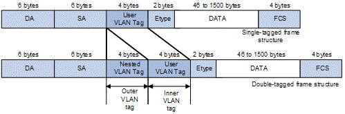
Figure 1-1 Single-tagged frame structure vs. double-tagged Ethernet frame structure
Advantages of QinQ:
l Addresses the shortage of public VLAN ID resource
l Enables customers to plan their own VLAN IDs, with running into conflicts with public network VLAN IDs.
l Provides an easy-to-do Layer 2 VPN solution for small-sized MANs or intranets.
& Note:
The QinQ feature requires configurations only on the service provider network, and not on the customer network.
1.1.2 Implementations of QinQ
There are two types of QinQ implementations: basic QinQ and selective QinQ.
1) Basic QinQ
Basic QinQ is a port-based feature, which is implemented through VLAN VPN.
With the VLAN VPN feature enabled on a port, when a frame arrives on the port, the switch will tag it with the port’s default VLAN tag, regardless of whether the frame is tagged or untagged. If the received frame is already tagged, this frame becomes a double-tagged frame; if it is an untagged frame, it is tagged with the port’s default VLAN tag.
2) Selective QinQ
Selective QinQ is an implementation more flexible than basic QinQ. In addition to all the functions of basic QinQ, selective QinQ can tag frames with different outer VLAN tags based on their inner VLAN IDs.
The S7500E series implements selective QinQ by using customer VLAN IDs as match criteria to classify frames and then tagging the frames that match a certain VLAN ID with the outer VLAN tag defined in the associated traffic behavior.
1.1.3 Modification of the TPID Value in VLAN Tags
A VLAN tag uses the tag protocol identifier (TPID) field to identify the protocol type of the tag. The value of this field, as defined in IEEE 802.1Q, is 0x8100.
Figure 1-2 shows the 802.1Q-defined tag structure of an Ethernet frame.
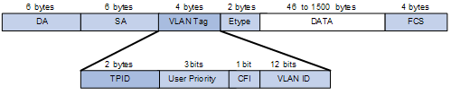
Figure 1-2 VLAN Tag structure of an Ethernet frame
The systems of different vendors may set the TPID in the outer VLAN tag of QinQ frames to different values. For compatibility with these systems, the S7500E series switches allow you to modify the TPID values in the VLAN tags in QinQ frames, including:
l The TPID value in customer network VLAN tags. The switch uses it to determine whether a frame received from the customer network is VLAN tagged. If the frame is considered as VLAN untagged, the switch tags the frame with the default VLAN tag of the receiving port. This default VLAN tag uses the TPID that you have configured.
l The TPID value in service provider network VLAN tags. The switch uses it to determine whether a frame received from the service provider network is VLAN tagged. In addition, the switch uses the configured TPID in the outer VLAN tag for customer network frames for compatibility with third-party devices.
The TPID in an Ethernet frame has the same position with the protocol type field in a frame without a VLAN tag. To avoid problems in packet forwarding and handling in the network, you cannot set the TPID value to any of the values in the table below.
Table 1-1 Reserved protocol type values
|
Protocol type |
Value |
|
ARP |
0x0806 |
|
PUP |
0x0200 |
|
RARP |
0x8035 |
|
IP |
0x0800 |
|
IPv6 |
0x86DD |
|
PPPoE |
0x8863/0x8864 |
|
MPLS |
0x8847/0x8848 |
|
IPX/SPX |
0x8137 |
|
IS-IS |
0x8000 |
|
LACP |
0x8809 |
|
802.1x |
0x888E |
|
Cluster |
0x88A7 |
|
Reserved |
0xFFFD/0xFFFE/0xFFFF |
1.2 Configuring Basic QinQ
Follow these steps to configure basic QinQ:
|
To do... |
Use the command... |
Remarks |
|
|
Enter system view |
system-view |
— |
|
|
Enter Ethernet port view or port group view |
Enter Ethernet port view |
interface interface-type interface-number |
Required Use either command. A command executed in Ethernet port view will take effect on the current port only; a command executed in port group view will take effect on all ports in the port group. |
|
Enter port group view |
port-group { manual port-group-name | aggregation agg-id } |
||
|
Enable QinQ on the port(s) |
qinq enable |
Required Disabled by default |
|
1.3 Configuring Selective QinQ
The outer VLAN tag added to a frame by the basic QinQ feature is the VLAN tag corresponding to the port’s default VLAN ID, while the selective QinQ feature allows adding different outer VLAN tags based on different inner VLAN tags.
With selective QinQ configured on a port, the device will add different outer VLAN tags based on the inner VLAN tags; frames with a VLAN ID out of the range specified in the raw-vlan-id inbound command will be forwarded unchanged.
Follow these steps to configure selective QinQ:
|
To do... |
Use the command... |
Remarks |
|
Enter system view |
system-view |
— |
|
Create a class and enter class view |
traffic classifier classifier-name [ operator { and | or } ] |
Required By default, the relationship between the match criteria in a class is logical AND. |
|
Specify the inner VLAN ID(s) of matching frames |
if-match customer-vlan-id vlan-id-list |
Required |
|
Exit to system view |
quit |
— |
|
Create a traffic behavior and enter traffic behavior view |
traffic behavior behavior-name |
Required |
|
Specify an outer VLAN ID |
nest top-most vlan-id vlan-id |
Required |
|
Exit to system view |
quit |
— |
|
Create a QoS policy and enter QoS policy view |
qos policy policy-name |
Required |
|
Tag the frames that carry a specified inner VLAN ID with the specified outer VLAN ID by associating the traffic behavior with the class |
classifier classifier-name behavior behavior-name |
Required |
|
Exit to system view |
quit |
— |
|
Enter the Ethernet port view of the customer network-side port |
interface interface-type interface-number |
— |
|
Enable basic QinQ |
qing enable |
Required |
|
Apply the QoS policy in the inbound direction |
qos apply policy policy-name inbound |
Required |
![]() Caution:
Caution:
l Before enabling selective QinQ on a port, enable basic QinQ on the port first. Selective QinQ enjoys higher priority than basic QinQ. Therefore, a received frame will be tagged with an outer VLAN ID based on basic QinQ only after it fails to match the match criteria defined in the traffic class.
l Selective QinQ is achieved through QoS policies. For detailed information about QoS policies, refer to the part talking about QoS.
1.4 Configuring the TPID of a VLAN Tag
Follow these steps to configure the TPID value of a VLAN tag:
|
To do... |
Use the command... |
Remarks |
|
|
Enter system view |
system-view |
— |
|
|
Configure the TPID in the customer network VLAN tags |
qinq ethernet-type customer-tag hex-value |
Optional 0x8100 by default. |
|
|
Enter Ethernet port view or port group view of a service provider-side port or ports |
Enter Ethernet port view |
interface interface-type interface-number |
Required Use either command. Configurations made in Ethernet port view will take effect on the current port only; configurations made in port group view will take effect on all ports in the port group. |
|
Enter port group view |
port-group { manual port-group-name | aggregation agg-id } |
||
|
Configure the TPID in the service provider network VLAN tags |
qinq ethernet-type hex-value |
Optional 0x8100 by default |
|
1.5 QinQ Configuration Example
I. Network requirements
l Provider A and Provider B are service provider network access devices.
l Customer A, Customer B, Customer C, and Customer D are customer network access devices.
l Provider A and Provider B are interconnected through a trunk port, which permits the frames of VLAN 1000, VLAN 2000, and VLAN 3000 to pass through.
l Third-party devices are deployed between Provider A and Provider B, with a TPID value of 0x8200.
The expected result of the configuration is as follows:
l VLAN 10 of Customer A and Customer B can intercommunicate across VLAN 1000 on the public network.
l VLAN 20 of Customer A and Customer C can intercommunicate across VLAN 2000 on the public network.
l Frames of the VLANs other than VLAN 20 of Customer A can be forwarded to Customer D across VLAN 3000 on the public network.
II. Network diagram
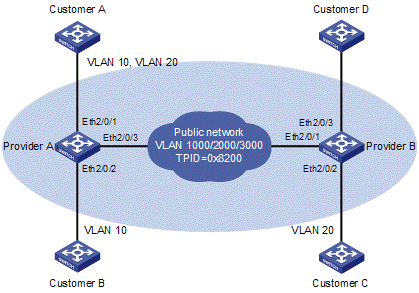
Figure 1-3 Network diagram for QinQ configuration
III. Configuration procedure
& Note:
With this configuration, the user must allow the QinQ packets to pass between the devices of the service providers.
1) Configuration on Provider A
# Enter system view.
<ProviderA> system-view
l Configuration on Ethernet 2/0/1
# Configure the port as a hybrid port permitting frames of VLAN 1000, VLAN 2000, and VLAN 3000 to pass through with the outer VLAN tag removed.
[ProviderA] interface ethernet 2/0/1
[ProviderA-Ethernet2/0/1] port link-type hybrid
[ProviderA-Ethernet2/0/1] port hybrid vlan 1000 2000 3000 untagged
# Configure VLAN 3000 as the default VLAN of Ethernet 2/0/1, and enable basic QinQ on Ethernet 2/0/1. As a result, the frames received on the port are tagged with the outer VLAN tag 3000.
[ProviderA-Ethernet2/0/1] port hybrid pvid vlan 3000
[ProviderA-Ethernet2/0/1] qinq enable
[ProviderA-Ethernet2/0/1] quit
# Create a class A10 to match frames of VLAN 10 of Customer A.
[ProviderA] traffic classifier A10
[ProviderA-classifier-A10] if-match customer-vlan-id 10
[ProviderA-classifier-A10] quit
# Create a traffic behavior P1000 and configure the action of tagging frames with the outer VLAN tag 1000 for the traffic behavior.
[ProviderA] traffic behavior P1000
[ProviderA-behavior-P1000] nest top-most vlan-id 1000
[ProviderA-behavior-P1000] quit
# Create a class A20 to match frames of VLAN 20 of Customer A.
[ProviderA] traffic classifier A20
[ProviderA-classifier-A20] if-match customer-vlan-id 20
[ProviderA-classifier-A20] quit
# Create a traffic behavior P2000 and configure the action of tagging frames with the outer VLAN tag 2000 for the traffic behavior.
[ProviderA] traffic behavior P2000
[ProviderA-behavior-P2000] nest top-most vlan-id 2000
[ProviderA-behavior-P2000] quit
# Create a QoS policy qinq. Associate the class A10 with the traffic behavior P1000, and associate the class A20 with the traffic behavior P2000 in the QoS policy qinq.
[ProviderA] qos policy qinq
[ProviderA-qospolicy-qinq] classifier A10 behavior P1000
[ProviderA-qospolicy-qinq] classifier A20 behavior P2000
[ProviderA-qospolicy-qinq] quit
# Apply the QoS policy qinq in the inbound direction of Ethernet 2/0/1.
[ProviderA] interface Ethernet 2/0/1
[ProviderA-Ethernet2/0/1] qos apply policy qinq inbound
l Configuration on Ethernet 2/0/2
# Configure VLAN 1000 as the default VLAN.
[ProviderA] interface ethernet 2/0/2
[ProviderA-Ethernet2/0/2] port access vlan 1000
# Enable basic QinQ. Tag frames from VLAN 10 with the outer VLAN tag 1000.
[ProviderA-Ethernet2/0/2] qinq enable
[ProviderA-Ethernet2/0/2] quit
l Configuration on Ethernet 2/0/3.
# Configure the port as a trunk port, and permit frames of VLAN 1000, VLAN 2000 and VLAN 3000 to pass.
[ProviderA] interface ethernet 2/0/3
[ProviderA-Ethernet2/0/3] port link-type trunk
[ProviderA-Ethernet2/0/3] port trunk permit vlan 1000 2000 3000
# To enable interoperability with the third-party devices in the public network, set the TPID of the service provider network VLAN tags to 0x8200. Therefore, the port tags the frames with the outer VLAN tag whose TPID is 0x8200.
[ProviderA-Ethernet2/0/3] qinq ethernet-type service-tag 8200
2) Configuration on Provider B
l Configuration on Ethernet 2/0/1
# Configure the port as a trunk port, and permit frames of VLAN 1000, VLAN 2000 and VLAN 3000 to pass.
<ProviderB> system-view
[ProviderB] interface ethernet 2/0/1
[ProviderB-Ethernet2/0/1] port link-type trunk
[ProviderB-Ethernet2/0/1] port trunk permit vlan 1000 2000 3000
# To enable interoperability with the third-party devices in the public network, set the TPID of the service provider network VLAN tags to 0x8200. Therefore, the port tags the received frames with the outer VLAN tag whose TPID is 0x8200.
[ProviderB-Ethernet2/0/1] qinq ethernet-type service-tag 8200
[ProviderB-Ethernet2/0/1] quit
l Configuration on Ethernet 2/0/2
# Configure VLAN 2000 as the default VLAN.
[ProviderB] interface ethernet 2/0/2
[ProviderB-Ethernet2/0/2] port access vlan 2000
# Enable basic QinQ. Tag frames from VLAN 20 with the outer VLAN tag 2000.
[ProviderB-Ethernet2/0/2] qinq enable
[ProviderB-Ethernet2/0/2] quit
l Configuration on Ethernet 2/0/3
# Configure VLAN 3000 as the default VLAN.
[ProviderB] interface ethernet 2/0/3
[ProviderB-Ethernet2/0/3] port access vlan 3000
# Enable basic QinQ to tag frames of all customer VLANs with the outer VLAN tag 3000.
[ProviderB-Ethernet2/0/3] qinq enable
3) Configuration on devices on the public network
As third-party devices are deployed between Provider A and Provider B, what we discuss here is only the basic configuration that should be made on the devices. Configure that device connecting with Ethernet 2/0/3 of Provider A and the device connecting with Ethernet 2/0/1 of Provider B so that their corresponding ports send tagged frames of VLAN 1000, VLAN 2000 and VLAN 3000. The configuration steps are omitted here.
Chapter 2 BPDU Tunneling Configuration
When configuring BPDU tunneling, go to these sections for information you are interested in:
l Introduction to BPDU Tunneling
l Configuring BPDU Transparent Transmission
l Configuring Destination Multicast MAC Address for BPDU Tunnel Frames
l BPDU Tunneling Configuration Example
2.1 Introduction to BPDU Tunneling
2.1.1 Why BPDU Tunneling
To avoid loops in your network, you can enable the spanning tree protocol (STP) on your device. However, STP gets aware of the topological structure of a network by means of bridge protocol data units (BPDUs) exchanged between different devices and the BPDUs are Layer 2 multicast packets, which can be received and processed by all STP-enabled devices on the network. This prevents each network from correctly calculating its spanning tree. As a result, when redundant links exist in a network, data loops will unavoidably occur.
By allowing each network to have its own spanning tree while running STP, BPDU tunneling can resolve this problem.
l BPDU tunneling can isolate BPDUs of different customer networks, so that one network is not affected by others while calculating the topological structure.
l BPDU tunneling enables BPDUs of the same customer network to be multicast over specific VLAN VPNs in the service provider network, so that the same, geographically dispersed customer network can implement consistent spanning tree calculation across the service provider network.
2.1.2 Understanding BPDU Tunneling
The BPDU tunneling implements the following two functions:
l BPDU isolation
l BPDU transparent transmission
I. BPDU isolation
When a port receives BPDUs of other networks, the port will discard the BPDUs, so that they will not take part in spanning tree calculation. Refer to Configuring BPDU Isolation.
II. BPDU transparent transmission
As shown in Figure 2-1, the upper part is the service provider network, and the lower part represents the customer networks. The customer networks include network A and network B. Enabling the BPDU tunneling function on the BPDU input/output devices across the service provider network allows BPDUs of the customer networks to be transparently transmitted in the service provider network, and allows each customer network to implement independent spanning tree calculation, without interfering each other. Refer to Configuring BPDU Transparent Transmission.
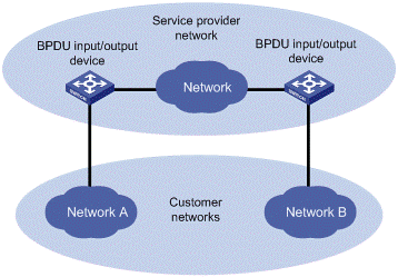
Figure 2-1 Network hierarchy of BPDU tunneling
l At the BPDU input side, the device changes the destination MAC address of a BPDU from a customer network from 0x0180-C200-0000 to a special multicast MAC address, 0x010F-E200-0003 by default. In the service provider’s network, the modified BPDUs are forwarded as data packets in the user VLAN.
l At the packet output side, the device recognizes the BPDU with the destination MAC address of 0x010F-E200-0003 and restores its original destination MAC address 0x0180-C200-0000. Then, the device removes the out-layer VLAN tag, and sends the BPDU to the destination customer network.
& Note:
Make sure, through configuration, that the VLAN tag of the BPDU is neither changed nor removed during its transparent transmission in the service provider network; otherwise, the system will fail to transparently transmit the customer network BPDU correctly.
2.2 Configuring BPDU Isolation
Perform the following tasks to configure BPDU isolation:
|
To do... |
Use the command... |
Remarks |
|
|
Enter system view |
system-view |
— |
|
|
Enable BPDU tunneling globally |
bpdu-tunnel dot1q enable |
Optional Enabled by default |
|
|
Enter Ethernet port view or port group view |
Enter Ethernet port view |
interface interface-type interface-number |
Required Use either command. Configurations made in Ethernet port view will take effect on the current port only; configurations made in port group view will take effect on all ports in the port group. |
|
Enter port group view |
port-group { manual port-group-name | aggregation agg-id } |
||
|
Enable BPDU tunneling on the port(s) |
bpdu-tunnel dot1q enable |
Required Disabled by default |
|
& Note:
l BPDU tunneling must be enabled globally before the BPDU tunnel configuration for a port can take effect.
l The BPDU tunneling feature is incompatible with the GVRP feature, so these two features cannot be enabled at the same time. For the description of GVRP, refer to VLAN Configuration.
2.3 Configuring BPDU Transparent Transmission
Perform the following tasks to configure BPDU transparent transmission:
|
To do... |
Use the command... |
Remarks |
|
|
Enter system view |
system-view |
— |
|
|
Enable BPDU tunneling globally |
bpdu-tunnel dot1q enable |
Optional Enabled by default |
|
|
Enter Ethernet port view or port group view |
Enter Ethernet port view |
interface interface-type interface-number |
Required Use either command. Configurations made in Ethernet port view will take effect on the current port only; configurations made in port group view will take effect on all ports in the port group. |
|
Enter port group view |
port-group { manual port-group-name | aggregation agg-id } |
||
|
Enable BPDU tunneling on the port(s) |
bpdu-tunnel dot1q enable |
Required Disabled by default |
|
|
Disable STP on the port(s) |
stp disable |
Required Enabled by default |
|
|
Enable BPDU tunneling for STP on the port(s) |
bpdu-tunnel dot1q stp |
Required Disabled by default |
|
& Note:
l BPDU tunneling must be enabled globally before the BPDU tunnel configuration for a port can take effect.
l The BPDU tunneling feature is incompatible with the GVRP feature, so these two features cannot be enabled at the same time. For the description of GVRP, refer to VLAN Configuration.
2.4 Configuring Destination Multicast MAC Address for BPDU Tunnel Frames
By default, the destination multicast MAC address for BPDU Tunnel frames is 0x010F-E200-0003. You can modify it to 0x0100-0CCD-CDD0, 0x0100-0CCD-CDD1 or 0x0100-0CCD-CDD2 through the following configuration.
Follow these steps to configure destination multicast MAC address for BPDU tunnel frames:
|
To do… |
Use the command… |
Remarks |
|
Enter system view |
system-view |
— |
|
Configure the destination multicast MAC address for BPDU Tunnel frames |
bpdu-tunnel tunnel-dmac mac-address |
Optional 0x010F-E200-0003 by default. |
2.5 BPDU Tunneling Configuration Example
I. Network requirements
l Customer A, Customer B, Customer C, and Customer D are customer network access devices.
l Provider A, Provider B, and Provider C are service provider network access devices, which are interconnected through configured trunk ports.
The configuration is required to satisfy the following requirements:
l Geographically dispersed customer networks Customer A, Customer C and Customer D can implement consistent spanning tree calculation across the service provider network.
l BPDU packets are isolated for the customer network Customer B, so it does not take part in the spanning tree calculation.
II. Network diagram
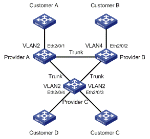
Figure 2-2 Network diagram for BPDU tunneling configuration
III. Configuration procedure
1) Configuration on Provider A
# Configure BPDU transparent transmission on Ethernet 2/0/1.
<ProviderA> system-view
[ProviderA] interface ethernet 2/0/1
[ProviderA-Ethernet2/0/1] port access vlan 2
[ProviderA-Ethernet2/0/1] stp disable
[ProviderA-Ethernet2/0/1] bpdu-tunnel dot1q enable
[ProviderA-Ethernet2/0/1] bpdu-tunnel dot1q stp
2) Configuration on Provider B
# Configure BPDU isolation on Ethernet 2/0/2.
<ProviderB> system-view
[ProviderB] interface ethernet 2/0/2
[ProviderB-Ethernet2/0/2] port access vlan 4
[ProviderB-Ethernet2/0/2] bpdu-tunnel dot1q enable
3) Configuration on Provider C
# Configure BPDU transparent transmission on Ethernet 2/0/3.
<ProviderC> system-view
[ProviderC] interface ethernet 2/0/3
[ProviderC-Ethernet2/0/3] port access vlan 2
[ProviderC-Ethernet2/0/3] stp disable
[ProviderC-Ethernet2/0/3] bpdu-tunnel dot1q enable
[ProviderC-Ethernet2/0/3] bpdu-tunnel dot1q stp
# Configure BPDU transparent transmission on Ethernet 2/0/4.
[ProviderC-Ethernet2/0/3] quit
[ProviderC] interface ethernet 2/0/4
[ProviderC-Ethernet2/0/4] port access vlan 2
[ProviderC-Ethernet2/0/4] stp disable
[ProviderC-Ethernet2/0/4] bpdu-tunnel dot1q enable
[ProviderC-Ethernet2/0/4] bpdu-tunnel dot1q stp
& Note:
When STP works stably on the customer network, if Customer A acts as the root bridge, the ports of Customer C and Customer D connected with Provider C can receive BPDUs from Customer A. Since BPDU isolation is enabled on Customer B, the port that connects Customer B to Provider B cannot receive BPDUs from Customer A.
