- Table of Contents
- Related Documents
-
| Title | Size | Download |
|---|---|---|
| 01-QoS Configuration | 534.56 KB |
1.2 QoS Configuration Task List
1.2.1 Configuring Service Parameter Allocation Rule
1.2.2 Configuring Traffic Policing
1.2.3 Configuring Traffic Shaping
1.2.4 Configuring Traffic Priority
1.2.5 Configuring Traffic Redirecting
1.2.6 Configuring Queue Scheduling
1.2.7 Configuring WRED Parameters
1.2.8 Configuring Traffic Mirroring
1.2.9 Configuring Port Mirroring
1.2.10 Configuring Traffic Accounting
1.3 Displaying and Debugging QoS Configuration
1.4 QoS Configuration Examples
1.4.1 Traffic Policing Configuration Example
1.4.2 Traffic Shaping Configuration Example
1.4.3 Port Mirroring Configuration Example
1.4.4 Traffic Priority Marking Configuration Example
1.4.5 Traffic Redirecting Configuration Example (I)
1.4.6 Traffic Redirecting Configuration Example (II)
1.4.7 Queue Scheduling Configuration Example
1.4.8 WRED Parameters Configuration Example
1.4.9 Traffic Accounting Configuration Example
Chapter 2 Port Tokens Configuration
2.2.1 Configuration Prerequisites
2.2.2 Configuring the Number of Tokens for Port or Port Queue
2.3 Port Tokens Configuration Example
Chapter 3 WAN-QoS Configuration
3.3 WAN-QoS Configuration Example
Chapter 4 Logon User ACL Control Configuration
4.1 Logon User ACL Control Overview
4.2 Configuring ACL for Telnet/SSH Users
4.2.1 Configuration Prerequisites
4.3 Layer 2 ACL Control Configuration Example
4.4 Basic ACL Control Configuration Example
4.5 Applying an ACL for SNMP Users
4.5.1 Configuration Prerequisites
4.6 ACL Control over SNMP Users Configuration Example
Chapter 5 VLAN-ACL Configuration
5.2.1 Configuration Prerequisites
5.3 VLAN-ACL Configuration Examples
5.3.1 VLAN-ACL Traffic Redirecting Configuration Example
5.3.2 VLAN-ACL Traffic Policing Configuration Example
6.2 EACL Configuration Task List
6.2.1 Configuring EACL-BT Rate Limit
6.2.2 Configuring EACL-reflexive ACL
6.2.3 Configuring EACL-Outgoing ACL
6.2.4 Configuring EACL-Incoming ACL
6.3.1 Reflexive ACL Configuration Example
6.3.2 EACL BT Rate Limit Configuration Example
Chapter 7 Global ACL Configuration
7.3 Global ACL Configuration Example
Chapter 8 WAN-ACL Configuration
8.3 WAN-ACL Configuration Example
Chapter 1 QoS Configuration
When configuring QoS, go to these sections for information you are interested in:
l Displaying and Debugging QoS Configuration
1.1 QoS Overview
1.1.1 Introduction
Conventional packet network treats all packets equally. Each switch/router processes all packets in First-in-First-out (FIFO) mode and then transfers them to the destination in the best effort, but it provides no commitment and guarantee to such transmission performance as delay and jitter.
With fast growth of computer networks, more and more data like voice and video that are sensitive to bandwidth, delay and jitter are transmitted over the network. This makes growing demands on quality of service (QoS) of networks.
Ethernet technology is a widely-used network technology dominant for independent LANs and many LANs based on Ethernet are organic parts of the Internet. In addition, Ethernet access is becoming one of the major access modes for Internet users. Therefore it is inevitable to consider Ethernet QoS if we want to achieve point-to-point global QoS solution. Ethernet switching devices then naturally need to provide different QoS guarantee for different types of services, especially for those which are sensitive to delay and jitter.
1.1.2 Terminology
I. Flow
Flow refers to a group of packets passing thought a switch.
II. Traffic classification
Traffic classification is the technology that identifies the packets with a specified attribute according to a specific rule. Classification rule refers to a packet filtering rule configured by an administrator. A classification rule can be very simple. For example, the switch can identify the packets of different priority levels according to the ToS (type of service) field in the packet headers. It can also be very complex. For example, it may contain information of the link layer (Layer 2), network layer (Layer 3) and transport layer (Layer 4) and the switch classifies packets according to such information as MAC address, IP protocol, source address, destination address and port ID. Classification rule often is limited to the information encapsulated at the packet header, rarely using packet contents.
III. Packet filtering
Packet filtering refers to filtering operation applied to traffic flow. For example, the deny operation drops the traffic flow which matches the classification rule and allows other traffic to pass. Ethernet switches use complex classification rules, so that traffic flow can be filtered purposefully to enhance network security.
There are two key steps in packet filtering:
Step 1: Classify the traffic at the port according to a specific rule.
Step 2: Run filtering operation (denying or permitting) to the identified traffic. By default, permit operation is selected.
IV. Traffic policing
QoS can police traffic at the ingress port, to provide better services with the limited network resources.
V. Redirection
You can re-specify forwarding direction for packets, based on QoS policy.
VI. Traffic priority
Ethernet switches can provide priority tags, including ToS, DSCP, 802.1p, and so on, for specific packets. These priority tags are respectively applicable to different QoS models.
The following describes IP priority, ToS priority, DSCP priority, EXP priority and 802.1p priority.
1) IP priority, ToS priority, DSCP priority and EXP priority
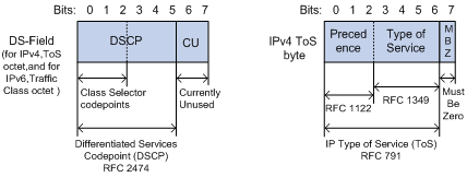
Figure 1-1 DS field and ToS byte
As shown in Figure 1-1, the ToS field in the IP header contains 8 bits. The first three bits represent IP priority, in the range of 0 to 7; bits 3-6 stand for ToS priority, in the range of 0 to 15. RFC2474 redefines the ToS field in IP packets as DS (differentiated services) field. The first six bits denote DSCP (differentiated services codepoint) priority, in the range of 0 to 63, and the latter two bits are reserved. EXP priority, a number ranging from 0 to 7 which is obtained by a mapping of the first three bits (bit 0 to 2) of DSCP priority, lies in MPLS (multiprotocol label switching) header.
2) 802.1p priority
802.1p priority is stored in the header of Layer 2 packets and is suitable for the case where only Layer 2 QoS guarantee, not L3 header analysis, is required.
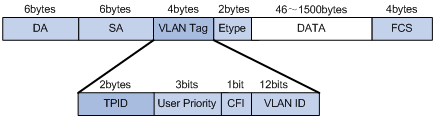
Figure 1-2 Ethernet frame with 802.1Q tag header
In the above figure, each host supporting 802.1Q protocol adds a 4-byte 802.1Q tag header after the source address in Ethernet header.
The 802.1Q tag header contains a 2-byte tag protocol identifier (TPID), with the default value 0x8100, and a 2-byte tag control information (TCI). The TPID is newly defined by IEEE to indicate that a packet is 802.1Q tagged. The TCI field consists of the User Priority, CFI, and VLAN ID fields.
The User Priority field in TCI stands for 802.1p priority, which consists of three bits. There are eight priority levels, numbered as 0 to 7, for determining to send which packets first when switch congestion takes place. Since their applications are defined in detail in the 802.1p Recommendation, they are named as 802.1p priority levels.
VII. Queue scheduling
Queue scheduling is used to resolve problems of resource contention by many packets. These algorithms are often used in queue scheduling: strict priority (SP) algorithm and weighted round Robin (WRR) algorithm.
1) SP algorithm
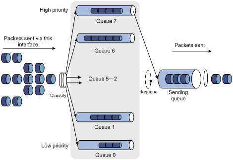
SP algorithm is designed for key services. One of the characteristics of key services is these services should be processed preferentially to minimize response delay in event of congestion. For example, there are eight output queues at the port, numbered respectively as 7 to 0, with priority levels in descending order.
In SP mode, the system first sends those packets of higher priority in strict accordance with priority order. Only when packets in high priority queue are all sent can those in lower priority queue be sent. This manner of putting key-service packets into high priority queues and non-key service packets into low priority queues does ensure that key-service packets are sent first, while non-key service packets are sent during the interval when no key-service packets need processed.
SP algorithm also has its disadvantages: If high priority queues are full, then packets from the low priority queues may not be forwarded.
2) WRR algorithm
Each port supports eight output queues except that port of the GV48D/GP48D/XP4 non-wire-speed board only supports four queues. In WRR mode, the system processes the queues by turn, so every queue can have a service period.
See the case where the port supports eight output queues. Every queue is assigned with a weight value (respectively numbered as w7, w6, w5, w4, w3, w2, w1, and w0), which indicates the weight in obtaining resources. For a 100 Mbps port, the weight values are set as 50, 30, 10, 10, 50, 30, 10 and 10 (corresponding respectively to w7, w6, w5, w4, w3, w2, w1, and w0). The even the queue with the lowest priority can be allocated with a 5 Mbps bandwidth.
Another merit for WRR algorithm: Though the queues are scheduled by turn, they are not configured with fixed time quantum. If a queue has no packets, the system immediately schedules the next queue. Then bandwidth resources can be fully utilized.
VIII. Traffic mirroring
Traffic mirroring duplicates the specified packets to CPU, a port, or a NetStream board for packet analysis and monitoring.
IX. Port mirroring
Port mirroring duplicates all packets at a specified port to the monitor port for network test and troubleshooting.
X. Flow-based traffic accounting
The system can collect traffic statistics based on flow for further analysis.
1.2 QoS Configuration Task List
Complete the following tasks to perform QoS configuration:
l Configuring Service Parameter Allocation Rule
l Configuring Traffic Policing
l Configuring Traffic Priority
l Configuring Traffic Redirecting
l Configuring Queue Scheduling
l Configuring Traffic Mirroring
l Configuring Traffic Accounting
& Note:
l Before initiating any of these QoS configuration tasks, you should first define the corresponding ACL. Then you can achieve packet filtering just by activating the right ACL.
l To configure packet filtering, you need only to activate corresponding ACL. For more information, see ACL Configuration in the QoS ACL Volume.
l In QoS configuration (including packet filtering, traffic policing, priority marking, traffic redirecting, traffic mirroring, and traffic accounting), if the specified advanced ACL has been occupied by IDS, QoS action cannot be delivered normally.
l The four ports (numbered 0 to 3) on an XP4B or XP4CA board each support four queues (queue 0 to 3) and support the configuration for queue scheduling.
l On an XP4B or XP4CA board, the following configurations can only be performed on port 0 and 2: applying user-defined flow template, port local precedence, packet filtering, priority marking, traffic policing, traffic redirecting, traffic mirroring, and traffic accounting. When such a configuration is performed on port 0, it takes effect on both port 0 and 1. Likewise, when such a configuration is performed on port 2, it takes effect on both port 2 and 3.
l With traffic policing configured on a XP4B or XP4CA board, port 0 and 1 share the same bandwidth, and port 2 and 3 do likewise. That is, port 0 and 1 share the traffic parameter settings on port 0, and port 2 and 3 share the traffic parameter settings on port 2.
l On an XP4B or XP4CA board, executing the traffic-statistic command on port 0 will collect traffic statistics on both port 0 and 1, and executing the command on port 2 will collect traffic statistics on both port 2 and 3.
l Ports on XP4B and XP4CA boards do not support traffic shaping (traffic-shape).
![]() Caution:
Caution:
l The syntax of the QoS configuration command used for service processor boards (LSB1NATB0 boards in the context of this document) is somewhat different from that for interface boards. See related description in the manual.
l The service processor boards now supported by the S9500 series have no egress interface. Therefore, they do not support the configuration commands in Ethernet port view.
l Service processor boards do not support Layer 2 ACL.
Some of QoS terms are listed in the following table.
|
Term |
Remarks |
|
CoS |
It has the same meaning as 802.1p priority. Both refer to the priority at packet header, with the value ranging from 0 to 7. |
|
Service parameters |
Switch allocates a set of parameters, which are used in achieving QoS functions, upon receiving a packet. Four items are included: 802.1p priority, DSCP priority, local precedence, and drop precedence. |
|
Drop-precedence |
One of service parameters, ranging from 0 to 2. Drop precedence is allocated when the switch receives the packet and may be when the packet is processed. Allocating drop precedence to the packet is also called coloring the packet: the packet with drop precedence 2 as red, that with drop precedence 1 as yellow and that with drop precedence 0 as green. Drop precedence is referred to when switch needs to drop packets in its congestion. |
|
Conform-Level |
The result calculated from the user-defined CIR, CBS, EBS, PIR and actual traffic when the switch runs traffic policing, in the range of 0 to 2. The parameter is used to select the remark service parameters, such as remark-cos and remark-drop, in traffic policing by means of the traffic-limit command. The packets with different conform-levels query different mapping tables. The conform-level of the packets whose traffic is smaller than cir is 0, the conform-level of the packets whose traffic is bigger than cir and smaller than pir is 1, and the conform-level of the packets whose traffic is bigger than pir is 2. It is also involved in the DSCP + Conform level-service parameter mapping table which is used in re-allocating service parameters to a packet with the traffic-priority command. Then conform level must be 0. |
1.2.1 Configuring Service Parameter Allocation Rule
QoS is based on service parameters, a set of parameters for a packet, including 802.1p priority (CoS priority), DSCP priority, EXP priority, local precedence and drop precedence.
After receiving a packet, the switch allocates a set of service parameters to it according to a specific rule. The switch first gets its local precedence and drop precedence according to the packet 802.1p priority value, by searching in the CoS-to-local precedence mapping table and the CoS-to-drop precedence mapping table. Default values are available for the two mapping tables, but you can also configure the mapping tables according to your needs. If the switch fails to allocate a local precedence for the packet, it uses the local precedence of the receiving port as the CoS value to search the CoS-to-local precedence mapping table for the local precedence of the packet. Then the switch inversely searches the default CoS-to-local precedence mapping table to obtain the CoS value and searches the CoS-to-drop precedence mapping table to obtain the drop precedence for the packet.
& Note:
l To assign a local precedence to the tagged packets received on a port based on the 802.1p field, you must assign a local precedence (or port priority) with the priority command to the port instead of using the default port priority, that is, 0.
l A tagged packet received on a port will be assigned a local precedence based on its 802.1p if the local precedence of the port is not zero or if the traffic-priority command is configured to have the system to do so.
l If the CoS-to-local precedence mapping table is modified, you need to re-assign a local precedence to each port for the new mapping table to take effect on untagged packets.
I. Configuring mapping tables
Perform the following configurations in system view.
|
To do... |
Use the command... |
|
Configure the CoS-to-drop precedence mapping table |
qos cos-drop-precedence-map cos0-map-drop-prec cos1-map-drop-prec cos2-map-drop-prec cos3-map-drop-prec cos4-map-drop-prec cos5-map-drop-prec cos6-map-drop-prec cos7-map-drop-prec |
|
Restore the default values of CoS-to-drop precedence mapping table |
undo qos cos-drop-precedence-map |
|
Configure the CoS-to-local precedence mapping table |
qos cos-local-precedence-map cos0-map-local-prec cos1-map-local-prec cos2-map-local-prec cos3-map-local-prec cos4-map-local-prec cos5-map-local-prec cos6-map-local-prec cos7-map-local-prec |
|
Restore the default values of CoS-to-local precedence mapping table |
undo qos cos-local-precedence-map |
By default, the switch uses the default mapping tables to assign drop precedence and local precedence to received packets.
II. Configuring local precedence on a port
Perform the following configurations in Ethernet port view.
|
To do... |
Use the command... |
|
Configure local precedence on a port |
priority priority-level |
|
Restore the default local precedence on a port |
undo priority |
1.2.2 Configuring Traffic Policing
Traffic policing performs per-flow rate limiting. In case the rate of a regulated traffic flow exceeds the specified traffic specifications, the switch drops the exceeding packets, reassigns service parameters for the traffic flow, or takes other actions as configured.
Traffic policing actions include reassigning service parameters for traffic with a certain conform level based on the DSCP-to-services mapping table or the EXP-to-services mapping table for the conform level and reassigning 802.1p priority based on the local precedence-to-802.1p mapping table for the conform level. You can edit these mapping tables or use the default ones.
I. Configuring mapping tables
Perform the following configurations in the specified views.
|
To do... |
Use the command... |
|
Enter conform level view (in system view) |
qos conform-level conform-level-value |
|
Configure the DSCP-to-services mapping table for the conform level (in conform level view) |
dscp dscp-list : dscp-value exp-value cos-value local-precedence-value drop-precedence |
|
Restore the default DSCP-to-services mapping table for the conform level (in conform level view) |
undo dscp dscp-list |
|
Configure the EXP-to-services mapping table for the conform level (in conform level view) |
exp exp-list : dscp-value exp-value cos-value local-precedence-value drop-precedence |
|
Restore the default EXP-to-services mapping table for the conform level (in conform level view) |
undo exp exp-list |
|
Configure the local precedence-to-802.1p mapping table for the conform level (in conform level view) |
local-precedence cos-value0 cos-value1 cos-value2 cos-value3 cos-value4 cos-value5 cos-value6 cos-value7 |
|
Restore the default local precedence-to-802.1p mapping table for the conform level (in conform level view) |
undo local-precedence |
The system provides default mapping tables.
II. Configuring traffic parameters (optional)
Use the following command to set the traffic parameters required before configuring traffic policing on service processor boards.
![]() Caution:
Caution:
This operation is not required for configuring traffic policing on common boards.
Perform the following configuration in system view.
|
To do... |
Use the command... |
|
Configure traffic parameters |
traffic-params traffic-index cir committed-info-rate cbs committed-base-size ebs exceed-base-size [ pir peak-info-rate ] |
III. Configuring traffic policing
The purpose of this configuration task is to implement traffic policing on ACL-matched data streams, and then take normal actions on data streams within the traffic limit and take other actions (discarding packets, for example) on those exceeding the limit.
For interface boards, perform the following configurations in Ethernet port view.
|
To do... |
Use the command... |
|
Configure traffic policing which only applies IP group ACL |
traffic-limit inbound ip-group { acl-number | acl-name } [ rule rule [ system-index index ] ] [ tc-index index ] cir cbs ebs [ pir ] [ conform { { remark-cos | remark-drop-priority } * | remark-policed-service } ] [ exceed { forward | drop } ] |
|
Remove traffic policing setting which only applies IP group ACL |
undo traffic-limit inbound ip-group { acl-number | acl-name } [ rule rule ] |
|
Configure traffic policing which applies IP group ACL and link group ACL at same time |
traffic-limit inbound ip-group { acl-number | acl-name } { rule rule link-group { acl-number | acl-name } [ rule rule [ system-index index ] ] | link-group { acl-number | acl-name } rule rule } [ tc-index index ] cir cbs ebs [ pir ] [ conform { { remark-cos | remark-drop-priority } * | remark-policed-service } ] [ exceed { forward | drop } ] |
|
Remove traffic policing setting which applies IP group ACL and link group ACL at same time |
undo traffic-limit inbound ip-group { acl-number | acl-name } { rule rule link-group { acl-number | acl-name } [ rule rule ] | link-group { acl-number | acl-name } rule rule } |
|
Configure traffic policing which only applies link group ACL |
traffic-limit inbound link-group { acl-number | acl-name } [ rule rule [ system-index index ] ] [ tc-index index ] cir cbs ebs [ pir ] [ conform { { remark-cos | remark-drop-priority } * | remark-policed-service } ] [ exceed { forward | drop } ] |
|
Remove traffic policing setting which only applies link group ACL |
undo traffic-limit inbound link-group { acl-number | acl-name } [ rule rule ] |
& Note:
It is required that CIR is less than or equal to PIR and CBS is less than or equal to EBS. You are recommended to configure CBS and EBS to numbers that are 100 to 150 times of CIR.
For service processor boards, perform the following configurations in VLAN view.
|
To do... |
Use the command... |
|
Configure traffic policing which only applies IP group ACL |
traffic-limit inbound ip-group { acl-number | acl-name } [ rule rule [ system-index index ] ] traffic-index index ] [ conform { { remark-cos | remark-policed-service } ] [ exceed { forward | drop } ] slot slot-id |
|
Remove traffic policing setting which only applies IP group ACL |
undo traffic-limit inbound ip-group { acl-number | acl-name } [ rule rule ] slot slot-id |
![]() Caution:
Caution:
l Before executing the traffic-limit command on a service processor board, you must first configure traffic redirecting in Ethernet port view to redirect the packets of a specific VLAN to the service processor board.
l Before configuring traffic policing, you must first define corresponding ACLs and configure the DSCP + Conform level-service parameters mapping table and the Local precedence + Conform level-802.1p priority mapping table.
You must first define the corresponding ACL and configure the DSCP + Conform level-service parameters mapping table and Local precedence + Conform level mapping table before starting this configuration.
This configuration achieves traffic policing for the packets that match the ACL. If the traffic rate threshold is exceeded, corresponding measures will be taken, for example, dropping excessive packets.
system-index index: Specifies a system index for the specified ACL rule. By default, when an ACL rule is applied, the system will automatically assign a globally unique index to the rule for the purpose to retrieve the rule later. You can also use the two parameters to specify a system index when using the command to apply an ACL rule. But the index you specified may change when the system is running. Generally, you are not recommended to manually specify the system index.
tc-index index here is traffic policing index. If you configure the same index for different ACL rules during setting traffic policing, then the sum of traffic shall be limited by the traffic policing-related parameters predefined. For example, if CIR (committed information rate) of the traffic that matches ACL 1 is set to 10 kbps and that for ACL 2 to 10 kbps, and their traffic policing indexes are the same, then the average rate of the traffic that matches ACL 1 and ACL 2 shall be limited to 10 kbps.
& Note:
l When you specify the same tc-index for different traffics, the traffic policing-related parameter settings must be consistent with each other. Otherwise, the system will prompt an error.
l For boards with C or D suffix in their names, if the remark-cos keyword is used, both remark-cos and remark-drop-priority will take effect.
l The index specified by the tc-index keyword should be in the range of 0 to 12288, where 0 directs the system to automatically assign an index.
See the corresponding Command Manual for details of the commands.
1.2.3 Configuring Traffic Shaping
Traffic shaping controls the rate of outbound packets, to ensure they are sent at relatively average rates. Traffic shaping measure tries to match packet transmission rate with the capacity of downstream devices. Its major difference from traffic policing is: Traffic shaping buffers packets at over-threshold rates to make them sent at average rates, while traffic policing drops excessive packets. Therefore, traffic shaping may increase transmission delay, but not for traffic policing.
Perform the following configurations in Ethernet port view.
|
To do... |
Use the command... |
|
Configure traffic shaping |
traffic-shape [ queue queue-id ] max-rate burst-size |
|
Remove traffic shaping setting |
undo traffic-shape [ queue queue-id ] |
The switch supports traffic shaping based on port, that is, all traffic on the port is shaped. It also supports traffic shaping for a specific queue. You can choose to achieve one of them by selecting different parameters in the command.
See the corresponding Command Manual for details of the commands.
1.2.4 Configuring Traffic Priority
This configuration re-marks priority value for the packets that match the ACL in these ways: using the service parameters allocated by the switch, re-allocating service parameters by searching the mapping table based on the packet DSCP value, re-allocating service parameters by searching the mapping table based on the specified DSCP or EXP value, customizing service parameters for the packets.
For interface boards, perform the following configurations in Ethernet port view.
|
To do... |
Use the command... |
|
Configure traffic priority which only applies IP group ACL |
traffic-priority inbound ip-group { acl-number | acl-name } [ rule rule [ system-index index ] ] { auto | remark-policed-service { trust-dscp | dscp dscp-value | untrusted dscp dscp-value cos cos-value local-precedence local-precedence drop-priority drop-level } } |
|
Remove traffic priority setting which only applies IP group ACL |
undo traffic-priority inbound ip-group { acl-number | acl-name } [ rule rule ] |
|
Configure traffic priority which applies IP group ACL and link group ACL at same time |
traffic-priority inbound ip-group { acl-number | acl-name } { rule rule link-group { acl-number | acl-name } [ rule rule [ system-index index ] ] | link-group { acl-number | acl-name } rule rule } { auto | remark-policed-service { trust-dscp | dscp dscp-value | untrusted dscp dscp-value cos cos-value local-precedence local-precedence drop-priority drop-level } } |
|
Remove traffic priority setting which applies IP group ACL and link group ACL at same time |
undo traffic-priority inbound ip-group { acl-number | acl-name } { rule rule link-group { acl-number | acl-name } [ rule rule ] | link-group { acl-number | acl-name } rule rule } |
|
Configure traffic priority which only applies link group ACL |
traffic-priority inbound link-group { acl-number | acl-name } [ rule rule [ system-index index ] ] { auto | remark-policed-service { trust-dscp | dscp dscp-value | untrusted dscp dscp-value cos cos-value local-precedence local-precedence drop-priority drop-level } } |
|
Remove traffic priority setting which only applies link group ACL |
undo traffic-priority inbound link-group { acl-number | acl-name } [ rule rule ] |
For service processor boards, perform the following configurations in VLAN view.
|
To do... |
Use the command... |
|
Mark the packets matching Layer 3 ACL rule with priority |
traffic-priority inbound ip-group { acl-number | acl-name } { rule rule { system-index index | { remark-policed-service { trust-dscp | dscp dscp-value | untrusted dscp dscp-value cos cos-value local-precedence local-precedence drop-priority drop-level [ slot slot-id ] } | auto [ slot slot-id ] } } | { auto [ slot slot-id ] } | { remark-policed-service { trust-dscp | dscp dscp-value | { untrusted dscp dscp-value cos cos-value local-precedence local-precedence drop-priority drop-level } [ slot slot-id ] } } } |
|
Remove the mark |
undo traffic-priority inbound ip-group { acl-number | acl-name } [ rule rule ] [ slot slot-id ] |
![]() Caution:
Caution:
l Before executing the traffic-priority command on a service processor board, you must first configure traffic redirecting in Ethernet port view to redirect the packets of a specific VLAN to the service processor board.
l Before performing this configuration, you must first define the ACLs and configure the DSCP-to-services mapping tables and the EXP-to-services mapping tables. For configuration of the mapping tables, refer to section Configuring Traffic Policing.
Normally, when applying a rule, the system assigns a globally unique index to it for later retrieval. Alternatively, you can choose to assign a system index to an ACL rule with this command. However, as this value may change while the system is running, you are not encouraged to manually assign system indexes to ACL rules.
& Note:
l For MPLS packets, the dscp-value argument defines not only a DSCP priority but also an EXP (the three high-order bits of the value). When the S9500 switch is used as an ingress PE device, for IP packets, EXP is matched according to the DSCP-to-services mapping table for the conform level of the packets; and for TCP and UDP packets, the value of EXP is the lower 3 bits of dscp-value. When the S9500 switch is used as an ingress P device, the value of EXP is the lower 3 bits of the dscp-value.
l For priority marking actions, the DSCP-to-services mapping table or EXP-to-services mapping table for conform level 0 applies.
See the corresponding command manual for details on the commands.
1.2.5 Configuring Traffic Redirecting
Traffic redirecting changes packet forwarding direction. You can redirect packets to CPU, an Ethernet port, an RPR logical interface, an aggregation group, a smart link group, an IP address, or a board.
For interface boards, perform the following configurations in Ethernet port view.
|
To do... |
Use the command... |
|
Configure traffic redirecting which only applies IP group ACL |
traffic-redirect inbound ip-group { acl-number | acl-name } [ rule rule [ system-index index ] ] { cpu | interface interface-type interface-number destination-vlan [ l2-vpn | l3-vpn ] | link-aggregation group groupid destination-vlan | smart-link group groupid destination-vlan | next-hop ip-addr1 [ ip-addr2 ] [ invalid { forward | drop } ] | slot slot-id { vlanid | designated-vlan vlanid } [ join-vlan ] } |
|
Remove traffic redirecting setting which only applies IP group ACL |
undo traffic-redirect inbound ip-group { acl-number | acl-name } [ rule rule ] |
|
Configure traffic redirecting which applies IP group ACL and link group ACL at same time |
traffic-redirect inbound ip-group { acl-number | acl-name } rule rule link-group { acl-number | acl-name } [ rule rule ] { cpu | interface interface-type interface-number destination-vlan [ l2-vpn | l3-vpn ] | link-aggregation group groupid destination-vlan | smart-link group groupid destination-vlan | next-hop ip-addr1 [ ip-addr2 ] [ invalid { forward | drop } ] | slot slot-id designated-vlan vlanid [ join-vlan ] } Or traffic-redirect inbound ip-group { acl-number | acl-name } link-group { acl-number | acl-name } rule rule { cpu | interface interface-type interface-number destination-vlan [ l2-vpn | l3-vpn ] | link-aggregation group groupid destination-vlan | smart-link group groupid destination-vlan | next-hop ip-addr1 [ ip-addr2 ] [ invalid { forward | drop } ] | slot slot-id designated-vlan vlanid [ join-vlan ] } |
|
Remove traffic redirecting setting which applies IP group ACL and link group ACL at same time |
undo traffic-redirect inbound ip-group { acl-number | acl-name } { rule rule link-group { acl-number | acl-name } [ rule rule ] | link-group { acl-number | acl-name } rule rule } or undo traffic-redirect inbound link-group { acl-number | acl-name } { rule rule ip-group { acl-number | acl-name } | ip-group { acl-number | acl-name } rule rule } |
|
Configure traffic redirecting which only applies link group ACL |
traffic-redirect inbound link-group { acl-number | acl-name } [ rule rule [ system-index index ] ] { cpu | interface interface-type interface-number destination-vlan [ l2-vpn | l3-vpn ] | link-aggregation group groupid destination-vlan | smart-link group groupid destination-vlan | next-hop ip-addr1 [ ip-addr2 ] [ invalid { forward | drop } ] | slot slot-id designated-vlan vlanid [ join-vlan ] } |
|
Remove traffic redirecting setting which only applies link group ACL |
undo traffic-redirect inbound link-group { acl-number | acl-name } [ rule rule ] |
![]() Caution:
Caution:
When the traffic is redirected to a NAT board with the vlanid argument specified, the port is allowed to exit the specified VLAN (by using the undo command or performing intermix). If a port leaves a VLAN by accident, you are recommended to remove the traffic redirecting configuration, add the port to the VLAN again, and then redirect the traffic to the NAT board with the vlanid argument specified.
For service processor boards, perform the following configurations in VLAN view.
|
To do... |
Use the command... |
|
Configure traffic redirecting on packets matching Layer 3 ACL rule. |
traffic-redirect inbound ip-group { acl-number | acl-name } { { rule rule { cpu [ slot slot-id ] | next-hop ip-addr1 [ ip-addr2 ] [ invalid { forward | drop } ] | system-index index { cpu [ slot slot-id ] | next-hop ip-addr1 [ ip-addr2 ] [ invalid { forward | drop } } } | { cpu [ slot slot-id ] } | { next-hop ip-addr1 [ ip-addr2 ] [ invalid { forward | drop } ] [ slot slot-id ] } } |
|
Remove this traffic redirecting configuration on the packets matching Layer 3 ACL rule. |
undo traffic-redirect inbound ip-group { acl-number | acl-name } [ rule rule ] [ slot slot-id ] |
The system-index index keyword-argument combination here is the system index for an ACL rule. When delivering a rule, the system assigns a globally unique index to it, for convenience of later retrieval. You can also assign a system index for it when delivering an ACL rule with this command, but the index value may change while the system is running. However, you are not recommended to assign a system index if not urgently necessary.
& Note:
l Traffic redirecting setting is only available for the permitted rules in the ACL.
l The packet redirected to the CPU cannot be forwarded normally.
l You can achieve policy route by selecting the next-hop keyword.
l Before executing the traffic-redirect command on a service processor board, you must first configure traffic redirecting in Ethernet port view to redirect the packets in Layer 3 to the service processor board and specific VLAN.
l Multicast packets are not allowed to be redirected to the service processor boards.
See the corresponding Command Manual for details of the commands.
1.2.6 Configuring Queue Scheduling
Each port supports eight output queues except that ports of GV48D/GP48D/XP4 non-wire-speed boards only support four queues. The switch puts the packets into the queues according to the local precedence of packets. Queue scheduling is used to resolve problems of resource contention by many packets. The switch supports SP algorithm and WRR algorithm.
Different output queues at the port may use different algorithms. The switch supports three scheduling modes:
1) All-SP scheduling mode
2) All-WRR mode: A queue is selected from each of the two WRR groups during scheduling, and then the two queues are compared for priority. The queue with higher priority will be scheduled. After scheduling, another queue is selected from the WRR group containing the queue with higher priority, and the newly selected queue will be compared with the previously selected queue that has lower priority.
3) SP plus WRR mode: The output queues are put into different scheduling groups. SP group uses SP algorithm, WRR groups use WRR algorithm. The select one queue respectively from SP group, WRR group 1 and WRR group 2 and schedule them using SP algorithm.
Perform the following configurations in Ethernet port view.
|
To do... |
Use the command... |
|
Configuring queue scheduling |
queue-scheduler wrr { group1 { queue-id queue-weight } &<1-8> | group2 { queue-id queue-weight } &<1-8> } * |
|
Restore the default setting |
undo queue-scheduler [ queue-id ] &<1-8> |
By default, the switch uses all-SP mode, so those queues not configured with WRR algorithm are SP mode.
See the corresponding Command Manual for details of the commands.
1.2.7 Configuring WRED Parameters
In the case of network congestion, the switch drops packets to release system resources. And then no packets are put into long-delay queues.
The switch allocates drop precedence for it when receiving a packet (also called coloring the packet). Drop precedence ranges from 0 to 2, with 2 for red, 1 for yellow, and 0 for green. In congestion, red packets will be first dropped, and green packets last.
You can configure drop parameters and thresholds by queue or drop precedence.
The following two drop modes are available:
1) Tail drop mode: Different queues (red, yellow and red) are allocated with different drop thresholds. When these thresholds are exceeded respectively, excessive packets will be dropped.
2) WRED drop mode: Drop precedence is taken into account in drop action. When only min-thresholds of red, yellow and green packets are exceeded, excessive packets are dropped randomly at given probability. But when max-thresholds of red, yellow and green packets are exceeded, all excessive packets will be dropped.
You must first configure WRED parameters for every output queue in defining drop precedence.
I. Configuring WRED parameters
The switch provides four sets of default WRED parameters, respectively numbered as 0 to 3. Each set includes 80 parameters, 10 parameters for each of the eight queues. The ten parameters are green-min-threshold, yellow-min-threshold, red-min-threshold, green-max-threshold, yellow-max-threshold, red-max-threshold, green-max-prob, yellow-max-prob, red-max-prob and exponent. Red, yellow and green packets respectively refer to those with drop precedence levels 2, 1, and 0.
Perform the following configurations in the specified views.
|
To do... |
Use the command... |
|
Enter WRED index view (system view) |
wred wred-index |
|
Restore the default WRED parameters (system view) |
undo wred wred-index |
|
Configure WRED parameters (WRED index view) |
queue queue-id green-min-threshold green-max-threshold green-max-prob yellow-min-threshold yellow-max-threshold yellow-max-prob red-min-threshold red-max-threshold red-max-prob exponent |
|
Restore the default WRED parameters (WRED index) |
undo queue queue-id |
The command restores the parameters of the specified WRED index as the default setting. The command restores the WRED parameters related to the queue as the default setting.
The switch provides four sets of WRED parameters by default.
![]() Caution:
Caution:
When multicast packets are sent through a certain port output queue, it is necessary to use the queue command to increase appropriately the length parameter of the corresponding queue where packets are all dropped to ensure the best effect of the replication capability of the egress port.
See the corresponding Command Manual for details of the commands.
II. Configuring drop algorithm
Perform the following configurations in Ethernet port view.
|
To do... |
Use the command... |
|
Configure drop algorithm |
drop-mode { tail-drop | wred } [ wred-index ] |
|
Restore the default algorithm |
undo drop-mode |
By default, tail drop mode is selected.
See the corresponding Command Manual for details of the commands.
1.2.8 Configuring Traffic Mirroring
Traffic mirroring duplicates the traffic that matches the specified ACL rule to CPU, a port, or a Netstream board for traffic analysis and monitoring.
Perform the following configurations in Ethernet port view.
|
To do... |
Use the command... |
|
Configure traffic mirroring which only applies IP group ACL |
mirrored-to inbound ip-group { acl-number | acl-name } [ rule rule [ system-index index ] ] { cpu | interface interface-type interface-number | slot slot-id } |
|
Remove traffic mirroring setting which only applies IP group ACL |
undo mirrored-to inbound ip-group { acl-number | acl-name } [ rule rule ] |
|
Configure traffic mirroring which applies IP group ACL and link group ACL at same time |
mirrored-to inbound ip-group { acl-number | acl-name } { rule rule link-group { acl-number | acl-name } [ rule rule [ system-index index ] ] | link-group { acl-number | acl-name } rule rule } { cpu | interface interface-type interface-number | slot slot-id } |
|
Remove traffic mirroring setting which applies IP group ACL and link group ACL at same time |
undo mirrored-to inbound ip-group { acl-number | acl-name } { rule rule link-group { acl-number | acl-name } [ rule rule ] | link-group { acl-number | acl-name } rule rule } |
|
Configure traffic mirroring which only applies link group ACL |
mirrored-to inbound link-group { acl-number | acl-name } [ rule rule [ system-index index ] ] { cpu | interface interface-type interface-number | slot slot-id } |
|
Remove traffic mirroring setting which only applies link group ACL |
undo mirrored-to inbound link-group { acl-number | acl-name } [ rule rule ] |
system-index index here is the system index for an ACL rule. When delivering a rule, the system assigns a globally unique index to it, for convenience of later retrieval. You can also assign a system index for it when delivering an ACL rule with this command, but the index value may change while the system is running. However, you are not recommended to assign a system index if not urgently necessary.
See the corresponding command manual for details of the commands.
Traffic mirroring configuration has the following restrictions:
1) ACL restrictions
l Only the inbound direction is supported.
l VLAN-ACLs and global ACLs are not supported.
l Only one destination port can be configured on a board.
l On the same board, the traffic mirroring destination port and the monitor port for port mirroring must be the same one.
2) Mirroring destination port restrictions
l It cannot be a member port of an aggregation group.
l It cannot be a non-Ethernet port, such as a POS interface, CPOS interface, E1/T1 interface, MP-group interface, channelized serial interface, ATM interface, or RPR port.
l It cannot be the same as the source port of traffic mirroring.
l It cannot be a port on an XP4B or XP4CA board.
l On a GV48 or GP48 board, only one destination port can be configured.
3) Source port restrictions for traffic mirroring
l A source port cannot be the same as the destination port.
l WAN interfaces, including CPOS interfaces, E1/T1 interfaces, MP-group interfaces, channelized serial interfaces, and ATM interfaces, cannot be configured as source ports.
l Ports on a C-type, CA-type, or XP4B board cannot be configured as source ports.
l If the source port is on a GV48 or GP48 board and the destination port is also on the board, the destination ports for inbound traffic mirroring and outbound traffic mirroring must be the same one.
When configuring traffic mirroring, note that:
l Outbound port traffic mirroring is not supported on the D-type boards with chip version 0.
l If the traffic-limit command is configured, traffic mirroring mirrors the traffic after rate limiting, while port mirroring mirrors all the traffic.
l If the traffic-priority command is configured, the mirrored traffic does not carry the newly marked DSCP.
l If the VLAN ID carried in a packet is allowed on the destination port (a trunk port), the VLAN tag will not be removed. Otherwise, the VLAN tag will be removed.
l When a packet received on an access port is mirrored to a trunk port in the default VLAN of the access port, the packet will be tagged.
l Packets mirrored from a GV48 or GP48 board are VLAN tagged.
1.2.9 Configuring Port Mirroring
Port mirroring duplicates data on the monitored port to the designated monitor port, for purpose of data analysis and supervision. The switch supports multiple-to-one mirroring, that is, you can duplicate packets from multiple ports to a monitor port.
You can also specify the monitoring direction:
l Only inbound packets
l Only outbound packets
Perform the following configurations in system view.
|
To do... |
Use the command... |
|
Configure port mirroring |
mirroring-group groupid { inbound | outbound } mirroring-port-list mirrored-to monitor-port |
|
Remove port mirroring setting |
undo mirroring-group groupid |
You can implement port mirroring configuration by setting mirroring groups at the port. Up to 20 mirroring groups can be configured at a port, with each group including one monitor port and multiple monitored ports.
& Note:
The S9500 series support cross-board mirroring, that is, the monitoring and monitored ports can be at different boards.
Note the following when configuring port mirroring:
l For intra-board mirroring, only one monitor port can be configured for the mirroring groups in the same direction.
l For cross-board mirroring, only one monitor port (which is on another board) can be configured for the mirroring groups in the same direction.
l You can only configure eight monitored ports for all the mirroring groups in transmit group.
l One port can act as mirroring port and mirrored port at the same time for different mirroring group.
More issues for the GV48 or GP48 board:
l For the mirroring (including incoming port mirroring and outgoing port mirroring) on the same GV48 or GP48 board, only one monitor port is allowed.
l For all mirroring groups configured in the system, only one monitor port is allowed on the same GV48 or GP48 board.
On XP4B and XP4CA boards, there are the following limitations on port mirroring:
Cross-board port mirroring is not supported. Port mirroring can only be configured between port 0 and 1, and between port 2 and 3. In each pair of ports (port 0 and 1, port 2 and 3), there can be one inbound monitor port and one outbound monitor port (other boards each can have only one inbound monitor port and one outbound monitor port).
See the corresponding Command Manual for details of the commands.
1.2.10 Configuring Traffic Accounting
Traffic accounting counts packets of the specific service traffic, that is, the packets match the defined ACL among those forwarded. You can view the information with the display qos-interface traffic-statistic command.
Perform the following configurations in Ethernet port.
|
To do... |
Use the command... |
|
Configure traffic accounting which only applies IP group ACL |
traffic-statistic inbound ip-group { acl-number | acl-name } [ rule rule [ system-index index ] ] [ tc-index index ] |
|
Remove traffic accounting setting which only applies IP group ACL |
undo traffic-statistic inbound ip-group { acl-number | acl-name } [ rule rule ] |
|
Configure traffic accounting which only applies link group ACL |
traffic-statistic inbound link-group { acl-number | acl-name } [ rule rule [ system-index index ] ] [ tc-index index ] |
|
Remove traffic accounting setting which only applies link group ACL |
undo traffic-statistic inbound link-group { acl-number | acl-name } [ rule rule ] |
|
Configure traffic accounting which applies IP group ACL and link group ACL |
traffic-statistic inbound ip-group { acl-number | acl-name } { rule rule link-group { acl-number | acl-name }{ rule rule [ system-index index ] | link-group { acl-number | acl-name } rule rule } [ tc-index index ] |
|
Remove traffic accounting setting which applies IP group ACL and link group ACL |
undo traffic-statistic inbound ip-group { acl-number | acl-name } { rule rule link-group { acl-number | acl-name }{ rule rule [ system-index index ] | link-group { acl-number | acl-name } rule rule } [ tc-index index ] |
|
Display the port traffic statistics information or the information of the rate at which traffic passes |
display qos-interface [ interface-type interface-number ] traffic-statistic [ rate [ timeinterval ] ] |
The system-index keyword specifies the system index for an ACL rule. When applying a rule, the system assigns a globally unique index to it for convenience of later retrieval. You can also assign a system index for it when delivering an ACL rule with this command, but the index value may change while the system is running. However, you are not recommended to assign a system index if not urgently necessary.
See the corresponding command manual for details on the commands.
& Note:
The index specified by the tc-index keyword should be in the range of 0 to 12288. A value of 0 specifies the system to assign indexes automatically.
1.3 Displaying and Debugging QoS Configuration
|
To do... |
Use the command... |
Remarks |
|
Display traffic mirroring configuration of a specific or all ports |
display qos-interface [ interface-type interface-number ] mirrored-to |
Available in any view |
|
Display priority marking configuration of a specific or all ports |
display qos-interface [ interface-type interface-number ] traffic-priority |
Available in any view |
|
Display traffic redirecting configuration of a port |
display qos-interface [ interface-type interface-number ] traffic-redirect |
Available in any view |
|
Display traffic accounting configuration of a specific or all ports |
display qos-interface [ interface-type interface-number ] traffic-statistic |
Available in any view |
|
Display port mirroring configuration |
display mirroring-group [ groupid ] |
Available in any view |
|
Display QoS configurations of a specific or all ports |
display qos-interface [ interface-type interface-number ] all |
Available in any view |
|
Display the drop mode of the output queues of a specific or all ports |
display qos-interface [ interface-type interface-number ] drop-mode |
Available in any view |
|
Display rate limiting configuration of a specific or all ports |
display qos-interface [ interface-type interface-number ] traffic-limit |
Available in any view |
|
Display queue scheduling configuration of a specific or all ports |
display qos-interface [ interface-type interface-number ] queue-scheduler |
Available in any view |
|
Display traffic shaping configuration of a specific or all ports |
display qos-interface [ interface-type interface-number ] traffic-shape |
Available in any view |
|
Display traffic policing configuration |
display traffic-params [ traffic-index ] |
Available in any view |
|
Display QoS configuration of a specific or all VLANs |
display qos-vlan [ vlan-id ] all |
Available in any view |
|
Display traffic priority configuration of a specific or all VLANs |
display qos-vlan [ vlan-id ] traffic-priority |
Available in any view |
|
Display traffic limit configuration of a specific or all VLANs |
display qos-vlan [ vlan-id ] traffic-limit |
Available in any view |
|
Display traffic direction configuration of a specific or all VLANs |
display qos-vlan [ vlan-id ] traffic-redirect |
Available in any view |
|
Display traffic statistics of a specific or all VLANs |
display qos-vlan [ vlan-id ] traffic-statistic |
Available in any view |
|
Display the DSCP-to-services mapping table, EXP-to-services mapping table, or local-precedence-to-802.1p mapping table for a conform level or all conform levels |
display qos conform-level [ conform-level-value ] { dscp-policed-service-map [ dscp-list ] | exp-policed-service-map | local-precedence-cos-map } |
Available in any view |
|
Display the CoS-to-drop precedence mapping table |
display qos cos-drop-precedence-map |
Available in any view |
|
Display the CoS-to-local precedence mapping table |
display qos cos-local-precedence-map |
Available in any view |
|
Display WRED parameter settings |
display wred [ wred-index ] |
Available in any view |
|
Clear traffic statistics |
reset traffic-statistic inbound { { ip-group { acl-number | acl-name } rule rule | link-group { acl-number | acl-name } } * | { ip-group { acl-number | acl-name } | link-group { acl-number | acl-name } rule rule } * | ip-group { acl-number | acl-name } rule rule link-group { acl-number | acl-name } rule rule } |
Available in user view |
1.4 QoS Configuration Examples
1.4.1 Traffic Policing Configuration Example
I. Network requirements
PC A, with IP address 10.10.10.10/24, is connected to Ethernet 3/1/1 of the Switch. PC B, with IP address 10.10.10.20/24, is connected to GigabitEthernet 7/1/1 of the Switch. Both Ethernet 3/1/1 and GigabitEthernet 7/1/1 belong to VLAN 10.
Configure traffic policing for ICMP packets received on Ethernet 3/1/1 and GigabitEthernet 7/1/1 with the following parameters: CIR 2000, CBS 200000, EBS 300000, and dropping the exceeding packets.
II. Network diagram
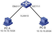
Figure 1-4 Network diagram for traffic policing configuration
III. Configuration procedure
# Configure VLAN 10 and create VLAN interface 10. Configure a proper IP address for the VLAN interface.
[H3C] vlan 10
[H3C-vlan10] port Ethernet 3/1/1
[H3C-vlan10] port GigabitEthernet 7/1/1
[H3C] interface Vlan-interface 10
[H3C-Vlan-interface10] ip address 10.10.10.1 255.255.255.0
# Create ACL 3000 to permit ICMP packets to pass through.
[H3C] acl number 3000
[H3C-acl-adv-3000] rule 0 permit icmp
[H3C-acl-adv-3000] quit
# Configure traffic policing on Ethernet 3/1/1 and GigabitEthernet 7/1/1 with the following parameters: CIR 2000, CBS 200000, EBS 300000, and dropping the exceeding packets.
[H3C] interface Ethernet 3/1/1
[H3C-Ethernet3/1/1] traffic-limit inbound ip-group 3000 2000 200000 300000
conform remark-drop-priority exceed drop
[H3C-Ethernet3/1/1] quit
[H3C] interface GigabitEthernet 7/1/1
[H3C-GigabitEthernet7/1/1] traffic-limit inbound ip-group 3000 2000 200000
300000 conform remark-drop-priority exceed drop
1.4.2 Traffic Shaping Configuration Example
I. Network requirements
Set traffic shaping for the output queue 2 at the port GE7/1/8, with the maximum rate of 650 Kbps and the burst size of 12 KB.
II. Network diagram
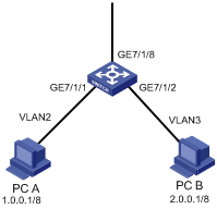
Figure 1-5 Network diagram for traffic shaping configuration
III. Configuration procedure
# Enter Ethernet port view.
<H3C> system-view
[H3C] interface GigabitEthernet 7/1/8
# Configure traffic shaping for the output queue 2 on GigabitEthernet 7/1/8: maximum rate 650 Kbps, burst size 12 KB.
[H3C-GigabitEthernet7/1/8] traffic-shape queue 2 650 12
1.4.3 Port Mirroring Configuration Example
I. Network requirements
Use one server to monitor the packets of two ports. R&D department is accessed from the port GE3/1/1 and sales department from the port GE3/1/2. The server is connected to the port GE3/1/8.
II. Network diagram

Figure 1-6 Network diagram for port mirroring configuration
III. Configuration procedure
# Define a mirroring group, with the monitor port as GigabitEthernet 3/1/8.
<H3C> system-view
[H3C] mirroring-group 1 inbound gigabitethernet3/1/1 gigabitethernet3/1/2 mirrored-to gigabitethernet3/1/8
[H3C] mirroring-group 2 outbound gigabitethernet3/1/1 gigabitethernet3/1/2 mirrored-to gigabitethernet3/1/8
1.4.4 Traffic Priority Marking Configuration Example
I. Network requirements
Re-allocate service parameters according to the mapping table for DSCP 63 for the packets sourced from PC A (with IP address 1.0.0.1) during the time range 8:00 to 18:00 everyday.
II. Network diagram
Figure 1-7 Network diagram for priority marking configuration
III. Configuration procedure
1) Define the time range.
# Define the time range from 8:00 to 18:00.
<H3C> system-view
[H3C] time-range test 8:00 to 18:00 daily
2) Define an ACL for the traffic sourced from PC A.
# Create ACL 2000 and enter the corresponding view.
[H3C] acl number 2000
# Define an ACL rule for the traffic sourced from PC A.
[H3C-acl-basic-2000] rule 0 permit source 1.0.0.1 0 time-range test
[H3C-acl-basic-2000] quit
3) Modify the DSCP-to-services mapping table for conform level 0.
# Modify the DSCP-to-services mapping table for conform level 0, with the DSCP being 63.
[H3C] qos conform-level 0
[H3C-conform-level-0] dscp 63 : 32 4 4 4 0
[H3C-conform-level-0] quit
The following table illustrates the modified DSCP-to-services mapping table for conform level 0.
Table 1-2 DSCP-to-services mapping table for conform level 0
|
Original DSCP |
CL |
Policed DSCP |
Policed exp |
Policed 802.1p |
Policed local precedence |
Policed drop precedence |
|
63 |
0 |
32 |
4 |
4 |
4 |
0 |
4) Re-allocate service parameters for the packets sourced from PC A.
# Re-allocate service parameters for the packets sourced from PC A.
[H3C] interface GigabitEthernet7/1/1
[H3C-GigabitEthernet7/1/1] traffic-priority inbound ip-group 2000 remark-policed-service dscp 63
1.4.5 Traffic Redirecting Configuration Example (I)
I. Network requirements
Forward the packets sourced from PC A (with IP address 1.0.0.1) during the time range from 8:00 to 18:00 every day to the address 2.0.0.1.
II. Network diagram
Figure 1-8 Network diagram for traffic redirecting configuration
III. Configuration procedure
1) Define the time range.
# Define the time range from 8:00 to 18:00.
<H3C> system-view
[H3C] time-range test 8:00 to 18:00 daily
2) Create an ACL for traffic sourced from PC A.
# Create ACL 2000 and enter the corresponding view.
[H3C] acl number 2000
# Define an ACL rule for the traffic sourced from PC A.
[H3C-acl-basic-2000] rule 0 permit source 1.0.0.1 0 time-range test
[H3C-acl-basic-2000] quit
3) Modify the next hop for the packets sourced from PC A.
# Configure the next hop for the packets sourced from PC A as 2.0.0.1.
[H3C] interface GigabitEthernet7/1/1
[H3C-GigabitEthernet7/1/1] traffic-redirect inbound ip-group 2000 rule 0 next-hop 2.0.0.1
1.4.6 Traffic Redirecting Configuration Example (II)
I. Network requirements
l All devices of a company are connected to GigabitEthernet 2/1/2 of the S9500 switch.
l The switch connects to the ISP router through two links. One is a gigabit link connecting to GigabitEthernet 2/1 of the switch, and the other is a 100 Mbps link connected to Ethernet 3/1/1 of the switch.
l GigabitEthernet 2/1/1 belongs to VLAN 20 whose VLAN interface IP address is 20.20.20.2/24. The IP address of the connected interface on the ISP router is 20.20.20.1/24.
l Ethernet 3/1/1 belongs to VLAN 30 whose VLAN interface IP address is 20.20.30.2/24. The IP address of the connected interface on the ISP router is 20.20.30.1/24.
Configure traffic redirecting to transmit packets with IP precedence 4, 5, 6, and 7 over the gigabit link and transmit other packets over the 100 Mbps link.
II. Network Diagram
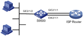
Figure 1-9 Network diagram for traffic redirecting configuration
III. Configuration procedure
# Configure VLAN 20 and VLAN 30. Configure IP addresses for their VLAN interfaces to allow the S9500 switch to communicate with the ISP router.
<H3C> system-view
[H3C] vlan 20
[H3C-vlan20] port gigabitethernet 2/1/1
[H3C-vlan20] quit
[H3C] interface Vlan-interface 20
[H3C-Vlan-interface20] ip address 20.20.20.2 255.255.255.0
[H3C-Vlan-interface20] quit
[H3C] vlan 30
[H3C-vlan30] port ethernet 3/1/1
[H3C-vlan30] quit
[H3C] interface Vlan-interface 30
[H3C-Vlan-interface30] ip address 20.20.30.2 255.255.255.0
# Configure a flow template for matching traffic by IP precedence and apply the flow template to GigabitEthernet 2/1/2.
[H3C] flow-template user-defined slot 2 ip-precedence
[H3C] interface GigabitEthernet 2/1/2
[H3C-GigabitEthernet2/1/2] flow-template user-defined
# Configure ACL 3000 and ACL 3100.
[H3C] acl number 3000
[H3C-acl-adv-3000] rule 0 permit ip precedence 7
[H3C-acl-adv-3000] rule 1 permit ip precedence 6
[H3C-acl-adv-3000] rule 2 permit ip precedence 5
[H3C-acl-adv-3000] rule 3 permit ip precedence 4
[H3C-acl-adv-3000] quit
[H3C] acl number 3100
[H3C-acl-adv-3100] rule 0 permit ip precedence 3
[H3C-acl-adv-3100] rule 1 permit ip precedence 2
[H3C-acl-adv-3100] rule 2 permit ip precedence 1
[H3C-acl-adv-3100] rule 3 permit ip precedence 0
[H3C-acl-adv-3100] quit
# Apply traffic redirecting rules to GigabitEthernet 2/1/2.
[H3C] interface GigabitEthernet 2/1/2
[H3C-GigabitEthernet2/1/2] traffic-redirect inbound ip-group 3000 next-hop 20.20.20.1
[H3C-GigabitEthernet2/1/2] traffic-redirect inbound ip-group 3100 next-hop 20.20.30.1
1.4.7 Queue Scheduling Configuration Example
I. Network requirements
Modify the correspondence between 802.1p priority levels and local priority levels to change the mapping between 802.1p priority levels and queues. That is, put packets into output queues according to the new mapping. Use WRR algorithm for the queues 0 to 5 at the port GE7/1/1. Set the queues 0, 1 and 2 into WRR queue 1, with weight respectively as 20, 20 and 30; set the queues 3, 4 and 5 into WRR queue 2, with weight respectively as 20, 20 and 40. The queues 6 and 7 use SP algorithm. See Configuring Queue Scheduling for the default mapping.
Table 1-3 802.1p-to-local precedence mapping table
|
802.1p priority |
Local precedence |
|
0 |
7 |
|
1 |
6 |
|
2 |
5 |
|
3 |
4 |
|
4 |
3 |
|
5 |
2 |
|
6 |
1 |
|
7 |
0 |
II. Network diagram
Figure 1-10 Network diagram for queue-schedule configuration
III. Configuration procedure
# Modify the mapping between 802.1p priority and local precedence.
<H3C> system-view
[H3C] qos cos-local-precedence-map 7 6 5 4 3 2 1 0
# Use WRR algorithm for the queues 0 through 5. Set the queues 0, 1, and 2 into WRR queue 1, with weight being 20, 20, and 30; set the queues 3, 4 and 5 into WRR queue 2, with weight being 20, 20, and 40. Use SP algorithm for the queues 6 and 7.
[H3C] interface GigabitEthernet7/1/1
[H3C-GigabitEthernet7/1/1] queue-scheduler wrr group1 0 20 1 20 2 30 group2 3 20 4 20 5 40
[H3C-GigabitEthernet7/1/1] return
<H3C> display qos-interface GigabitEthernet7/1/1 queue-scheduler
GigabitEthernet7/1/1 Port scheduling:
QID: scheduling-group weight
-----------------------------------
0 : wrr , group1 20
1 : wrr , group1 20
2 : wrr , group1 30
3 : wrr , group2 20
4 : wrr , group2 20
5 : wrr , group2 40
6 : sp 0
7 : sp 0
1.4.8 WRED Parameters Configuration Example
I. Network requirements
Set WRED parameters and drop algorithm for packets at the port GE7/1/1: Configure parameters for WRED 0; output queue ID is 7; green-min-threshold is 150; green-max-threshold is 500; green-max-prob is 5; yellow-min-threshold is 100; yellow-max-threshold is 150; yellow-max-prob is 10; red-min-threshold is 50; red-max-threshold is 100; red-max-prob is 15; exponent is 10; the port is in WRED drop mode; import the parameters of WRED 0.
II. Network diagram
Figure 1-11 Network diagram for WRED parameters configuration
III. Configuration procedure
1) Configure WRED parameters
# Configure parameters for WRED 0.
<H3C> system-view
[H3C] wred 0
[H3C-wred-0] queue 7 150 500 5 100 150 10 50 100 15 10
[H3C-wred-0] quit
2) Set drop algorithm and thresholds.
# Define the port GE7/1/1 in WRED drop mode, set the parameters of WRED 0.
[H3C] interface GigabitEthernet7/1/1
[H3C-GigabitEthernet7/1/1] drop-mode wred 0
1.4.9 Traffic Accounting Configuration Example
I. Network requirements
Suppose the IP address of PC A is 1.0.0.1 and that of PC B is 2.0.0.1. The switch is up-linked through the port GE7/1/8. Count the packets sent from the switch to PC A during the time range from 8:00 to 18:00 every day.
II. Network diagram
Figure 1-12 Network diagram for traffic accounting configuration
III. Configuration procedure
1) Define the time range.
# Define the time range from 8:00 to 18:00.
<H3C> system-view
[H3C] time-range test 8:00 to 18:00 daily
2) Create an ACL for the traffic sourced from PC A.
# Create ACL 2000 and define an ACL rule for the traffic sourced from PC A.
[H3C] acl number 2000
[H3C-acl-basic-2000] rule 0 permit source 1.0.0.1 0.0.0.0 time-range test
[H3C-acl-basic-2000] quit
3) Collect the statistics about the packets sourced from PC A and display the result using the display command.
[H3C] interface GigabitEthernet7/1/1
[H3C-GigabitEthernet7/1/1] traffic-statistic inbound ip-group 2000 rule 0
[H3C-GigabitEthernet7/1/1] quit
[H3C] display qos-interface GigabitEthernet7/1/1 traffic-statistic
GigabitEthernet7/1/1: traffic-statistic
Inbound:
Matches: Acl 2000 rule 0 running
640000 bytes (green 640000 byte(s), yellow 0 byte(s), red 0 byte(s) )
10000 packets
Chapter 2 Port Tokens Configuration
When configuring port tokens, go to these sections for information you are interested in:
l Overview
l Port Tokens Configuration Example
2.1 Overview
In practical application of S9500 series routing switches, when Layer 3 multicast traffic needs to be copied to multiple VLANs configured on an outbound port, packet loss may occur if relatively few packets can be buffer due to insufficient tokens on the outbound port or lower queue-tail drop threshold.
In a multicast environment, the number of tokens on a port and the queue length affect the copy capability of multicast, and queue assignment for multicast flows has indeterminateness. So, there is a need to flexibly adjust the number of tokens on port, in order to provide better multicast capability.
2.2 Port Tokens Configuration
In some situations, such as when traffic is flowing from a 1000 Mbps port to a 100 Mbps port, or the packet size of traffic is variable, packet loss may occur due to improper assignment of tokens. In such cases, you can adjust the number of tokens on individual ports or output queues of ports to resolve this problem.
2.2.1 Configuration Prerequisites
None
2.2.2 Configuring the Number of Tokens for Port or Port Queue
Follow these steps to configure the number of tokens for port or port queue:
|
To do... |
Use the command... |
Remarks |
|
Enter system view |
system-view |
— |
|
Configure the total number of tokens for each specified port or the number of tokens for a specified queue of each specified port |
qos token interface-list [ queue queue-id ] token-number |
Optional interface-list is a port list, in which you can specify the following ports: Ethernet port, POS port and RPR logical port. |
![]() Caution:
Caution:
l 100 Mbps Ethernet ports do not support the qos token command.
l Ports on the LSB1TGX1B and LSB1GV48DB boards do not support the qos token command.
l On the LSB1P4G8B, LSB1P4G8C, LSB1P4G8CA and LSB1SP4CA boards, you can configure the qos token command on only one of the four POS ports.
l On the LSB1XP4B and LSB1XP4CA boards, port 1 and 3 support the qos token command, while port 2 and 4 do not support the command.
2.3 Port Tokens Configuration Example
I. Configuration procedure
# Set the total number of tokens for port GigabitEthernet 3/1/1 to 30.
<H3C> system-view
System View: return to User View with Ctrl+Z.
[H3C] qos token GigabitEthernet3/1/1 30
# Set the number of tokens for queue 2 on port GigabitEthernet 3/1/1 to 5.
<H3C> system-view
System View: return to User View with Ctrl+Z.
[H3C] qos token GigabitEthernet3/1/1 queue 2 5
Chapter 3 WAN-QoS Configuration
When configuring WAN-QoS, go to these section for information you are interested in:
l Overview
l WAN-QoS Configuration Example
3.1 Overview
WAN-QoS refers to QoS applied to WAN interfaces. You can configure QoS commands on a WAN interface to implement QoS functions in the downlink direction of the WAN interface.
In this section, WAN interfaces refer to the channelized interfaces on CPOS and E1/T1 boards and the MP group interfaces formed by these channelized interfaces.
3.2 Configuring WAN-QoS
Follow these steps to configure WAN-QoS:
|
To do… |
Use the command… |
Remarks |
|
Enter system view |
system-view |
— |
|
Enter WAN interface view |
interface interface-type interface-number |
This interface could be a channelized CPOS or E1/T1 interface or an MP group interface formed by such channelized interfaces. |
|
Enable QoS on the WAN interface |
qos enable |
Required |
|
Set the tail drop thresholds |
queue queue-id tail-drop dp0-threshold dp1-threshold dp2-threshold |
Optional |
|
Configure the queue scheduling mode |
queue-scheduler wrr group { queue-id queue-weight } &<1-4> |
Optional |
|
Exit to system view |
quit |
— |
|
Display the QoS configuration of the specified or all WAN interfaces |
display qos-interface [ interface-type interface-number ] all |
Available in any view |
|
Display the drop mode configuration of the output queues on the specified or all WAN interfaces |
display qos-interface [ interface-type interface-number ] drop-mode |
|
|
Display the queue scheduling mode and parameters of the specified or all WAN interfaces |
display qos-interface [ interface-type interface-number ] queue-scheduler |
WAN-QoS configuration has the following restrictions:
l WAN-QoS is available only on CPOS or E1/T1 channelized interfaces or MP group interfaces formed by CPOS or E1/T1 channelized interfaces.
l On each WAN board, you can configure QoS on up to 64 channelized interfaces (including MP-group interfaces).
l A channel supports only four priority queues.
l WAN-QoS does not support traffic shaping.
The CoS-to-local precedence and CoS-to-drop precedence mapping tables for WAN-QoS are not configurable. Table 3-1 shows the two mapping tables.
Table 3-1 The CoS-to-local precedence and CoS-to-drop precedence mapping tables
|
Cos |
0 |
1 |
2 |
3 |
4 |
5 |
6 |
7 |
|
Local precedence |
0 |
0 |
1 |
1 |
2 |
2 |
2 |
3 |
|
Drop precedence |
1 |
0 |
1 |
0 |
2 |
1 |
0 |
0 |
3.3 WAN-QoS Configuration Example
I. Network requirements
Use an E1 cable to directly connect an E1 interface of Switch A and an E1 interface of Switch B. Bundle timeslots 1 to 31 into a channel, and connect the two devices using PPP. Switch B uses the clock of Switch A for reference. The traffic from Switch B to Switch A is assigned to four priority queues scheduled by WRR at the ratio of 5:5:10:15.
II. Network Diagram
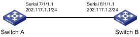
Figure 3-1 Network diagram for WAN-QoS configuration
III. Configuration procedure
1) Configuration on Switch A
# Configure interface E1 7/1/1.
<H3C> system-view
[H3C] controller e1 7/1/1
[H3C-E17/1/1] clock master
[H3C-E17/1/1] channel-set 1 timeslot-list 1-31
[H3C] interface serial 7/1/1:1
[H3C-Serial7/1/1:1] ip address 202.117.1.1 24
2) Configuration on Switch B
# Configure interface E1 8/1/1.
<H3C> system-view
[H3C] controller e1 8/1/1
[H3C-E18/1/1] clock slave
[H3C-E18/1/1] channel-set 1 timeslot-list 1-31
[H3C] interface serial 8/1/1:1
[H3C-Serial8/1/1:1] ip address 202.117.1.2 24
[H3C-Serial8/1/1:1] qos enable
[H3C-Serial8/1/1:1] queue-scheduler wrr group 0 5 1 5 2 10 3 15
Chapter 4 Logon User ACL Control Configuration
When configuring logon user ACL control, go to these sections for information you are interested in:
l Logon User ACL Control Overview
l Configuring ACL for Telnet/SSH Users
l Applying an ACL for SNMP Users
l Layer 2 ACL Control Configuration Example
l Basic ACL Control Configuration Example
l ACL Control over SNMP Users Configuration Example
4.1 Logon User ACL Control Overview
Currently, an S9500 series switch provides the following three measures for remote access:
l Telnet
l Security shell (SSH)
l Simple network management protocol (SNMP)
An S9500 series switch provides security control for these three access measures to prevent unauthorized users from logging in/and accessing it. There are two levels of security controls.
l The first level is implemented by applying ACLs to filter the users that are to connect to the switch. Only authorized users are capable of accessing the switch.
l The second level is implemented by password authentication. A user can log into the switch only after passing the password authentication.
This chapter mainly describes how to configure the first level security control over these access measures, that is, how to filter the users logging onto the switch with ACL.
4.2 Configuring ACL for Telnet/SSH Users
You can configure ACLs for the users who access the switch through Telnet or SSH to filter out the malicious or unauthorized connection requests before the password authentication to secure the switch.
4.2.1 Configuration Prerequisites
You have correctly configured the switch using Telnet or SSH.
4.2.2 Configuration Tasks
Follow these steps to configure ACL for Telnet/SSH users:
|
To do… |
Use the command... |
Remarks |
|
|
Enter system view |
system-view |
— |
|
|
Define an ACL and enter ACL view |
acl number acl-number [ match-order { config | auto } ] |
Required The command can only define a number-identified ACL |
|
|
Define rules |
Basic ACL view |
rule [ rule-id ] { permit | deny } protocol [ packet-level { bridge | route } | source { source-addr wildcard | any } | fragment | time-range name | vpn-instance instance-name ] * |
When Telnet and SSH users use basic and advanced ACLs, only the parameters source-addr and the wildcard, dest-addr and the wildcard parameter, and the time-range keyword in the command are valid. |
|
Advanced ACL view |
rule [ rule-id ] { permit | deny } protocol [ packet-level { bridge | route } | source { source-addr wildcard | any } | destination { dest-addr wildcard | any } | source-port operator port1 [ port2 ] | destination-port operator port1 [ port2 ] | icmp-type type code | established | { match-any | match-all } { urg | ack| psh | rst | syn | fin } | precedence precedence | tos tos | dscp dscp | fragment | bt-flag | time-range name | vpn-instance instance-name | ttl ttl-value ] * |
||
|
Layer 2 ACL view |
rule [ rule-id ] { permit | deny } [ packet-level { bridge | route } | cos cos-value | c-tag-cos c-cos-value | exp exp-value | protocol-type | mac-type { any-broadcast-packet | arp-broadcast-packet | non-arp-broadcast-packet | { { unicast-packet | multicast-packet } [ known | unknown ] } } | ingress { { source-vlan-id [ to source-vlan-id-end ] | source-mac-addr source-mac-wildcard | c-tag-vlan c-tag-vlan } * | any } | egress { dest-mac-addr dest-mac-wildcard | any } | s-tag-vlan s-tag-vlanid | time-range name ] * |
When Telnet and SSH users use a Layer 2 ACL, only the source-mac-addr and the source-mac-wildcard parameter, and the time-range keyword in the command are valid. |
|
|
Exit ACL view |
quit |
— |
|
|
Enter user interface view |
user-interface [ type ] first-number |
— |
|
|
Apply ACLs to restrict inbound/outbound requests of Telnet or SSH users |
Apply basic or advanced ACLs |
acl acl-number1 { inbound | outbound } |
The acl-number1 parameter indicates the number of the basic or advanced ACLs, in the range of 2,000 to 3,999. |
|
Apply Layer 2 ACLS |
acl acl-number2 inbound |
The acl-number2 parameter indicates the number of the Layer 2 ACL, in the range of 4,000 to 4,999. |
|
By default, the system does not restrict incoming/outgoing requests.
& Note:
l You can only use number-based ACLs to implement the ACL control to Telnet or SSH users.
l When you use the basic or advanced ACL to implement the ACL control to Telnet or SSH users, the incoming/outgoing requests are restricted based on the source or destination IP addresses. Therefore, only the source-addr and the wildcard, and dest-addr and the wildcard parameters, and the time-range keyword in the corresponding command are valid. Similarly, when you use the Layer 2 ACL to implement the ACL control to the Telnet or SSH users, the incoming/outgoing requests are restricted based on the source MAC address. Therefore, only the source-mac-addr and the source-mac-wildcard parameters, and the time-range keyword in the corresponding command are valid.
l When you use Layer 2 ACLs to implement the ACL control to the Telnet or SSH users, only incoming requests are restricted.
l If a user fails to log in due to ACL restriction, the system logs the user failure, including the IP address, login method, user interface index value, and failure reason.
4.3 Layer 2 ACL Control Configuration Example
I. Network requirements
Only the Telnet users with source MAC addresses 00A2-FC01-0101 and 00A2-FC01-0303 are allowed to access the switch.
II. Network diagram

Figure 4-1 Network diagram for Layer 2 ACL control configuration
III. Configuration procedure
# Create a Layer 2 ACL.
<H3C>system-view
System View: return to User View with Ctrl+Z.
[H3C] acl number 4000 match-order config
# Define ACL rules for ACL 4000.
[H3C-acl-link-4000] rule 1 permit ingress 00a2-fc01-0101 0000-0000-0000 [H3C-acl-link-4000] rule 2 permit ingress 00a2-fc01-0303 0000-0000-0000
[H3C-acl-link-4000] rule 3 deny ingress any
[H3C-acl-link-4000] quit
# Enter user interface view.
[H3C] user-interface vty 0 4
# Apply the Layer 2 ACL to restrict incoming requests.
[H3C-user-interface-vty0-4] acl 4000 inbound
4.4 Basic ACL Control Configuration Example
I. Network requirements
Only the Telnet users with IP addresses of 10.110.100.52 and 10.110.100.46 can access the switch.
II. Network diagram

Figure 4-2 Network diagram for basic ACL control configuration
III. Configuration procedure
# Create ACL 2000.
<H3C>system-view
System View: return to User View with Ctrl+Z.
[H3C] acl number 2000 match-order config
# Define ACL rules for ACL 2000.
[H3C-acl-basic-2000] rule 1 permit source 10.110.100.52 0
[H3C-acl-basic-2000] rule 2 permit source 10.110.100.46 0
[H3C-acl-basic-2000] rule 3 deny source any
[H3C-acl-basic-2000] quit
# Enter user interface view.
[H3C] user-interface vty 0 4
# Apply the ACL.
[H3C-user-interface-vty0-4] acl 2000 inbound
4.5 Applying an ACL for SNMP Users
S9500 series switches can be managed remotely through network management software (NMS). Administrators can use SNMP to access an S9500 series switch. Proper ACL configuration can prevent unauthorized network management users from logging onto the switch.
4.5.1 Configuration Prerequisites
Users can log into the switch using SNMP successfully.
4.5.2 Configuration Tasks
Follow these steps to apply an ACL for SNMP users:
|
To do… |
Use the command... |
Remarks |
|
|
Enter system view |
system-view |
— |
|
|
Create an ACL and enter ACL view |
acl number acl-number [ match-order { config | auto } ] |
Required This command can only define a number-based basic ACL. The acl-number parameter ranges from 2,000 to 2,999. |
|
|
Define basic ACL rules |
rule [ rule-id ] { permit | deny } protocol [ packet-level { bridge | route } | source { source-addr wildcard | any } | fragment | time-range name | vpn-instance instance-name ] * |
Required |
|
|
Exit ACL view |
quit |
— |
|
|
Apply the ACL to control SNMP users |
Apply the ACL in the snmp-agent community command |
snmp-agent community { read | write } community-name [ mib-view view-name ] [ acl acl-number ] |
The SNMP community name is a feature of SNMP V1 and SNMP V2. Applying an ACL in the snmp-agent community command filters the network management systems based on SNMP V1 and SNMP V2. |
|
Apply the ACL in the snmp-agent group command |
snmp-agent group { v1 | v2c } group-name [ read-view read-view ] [ write-view write-view ] [ notify-view notify-view ] [ acl acl-number ] snmp-agent group v3 group-name [ authentication | privacy ] [ read-view read-view ] [ write-view write-view ] [ notify-view notify-view ] [ acl acl-number ] |
The SNMP group and user name are features of SNMP V2 and later. Applying ACLs in the snmp-agent group, snmp-agent group v3, snmp-agent usm-user, and snmp-agent usm-user v3 commands filters the network management systems based on SNMP V2 and later. If you apply ACLs in these two groups of commands simultaneously, the switch filters network management users according to the both features. |
|
|
Import the ACL into the snmp-agent usm-user command |
snmp-agent usm-user { v1 | v2c } user-name group-name [ acl acl-number ] snmp-agent usm-user v3 user-name group-name [ authentication-mode { md5 | sha } auth-password ] [ privacy-mode des56 priv-password ] [ acl acl-number ] |
||
& Note:
l You can apply different ACLs in the snmp-agent community, snmp-agent group and snmp-agent usm-use commands.
l You can only apply number-based basic ACLs to implement ACL control over SNMP users.
4.6 ACL Control over SNMP Users Configuration Example
I. Network requirements
Only SNMP users from 10.110.100.52 and 10.110.100.46 can access the switch.
II. Network diagram
Figure 4-3 Network diagram for ACL control over SNMP users
III. Configuration procedure
# Create a basic ACL and define rules for it.
<H3C> system-view
System View: return to User View with Ctrl+Z.
[H3C] acl number 2000 match-order config
[H3C-acl-basic-2000] rule 1 permit source 10.110.100.52 0
[H3C-acl-basic-2000] rule 2 permit source 10.110.100.46 0
[H3C-acl-basic-2000] rule 3 deny source any
[H3C-acl-basic-2000] quit
# Apply the ACL.
[H3C] snmp-agent community read test acl 2000
[H3C] snmp-agent group v3 testgroup acl 2000
[H3C] snmp-agent usm-user v3 testuser testgroup acl 2000
Chapter 5 VLAN-ACL Configuration
When configuring VLAN-ACL, go to these sections for information you are interested in:
l VLAN-ACL Configuration Examples
5.1 VLAN-ACL Overview
VLAN-ACL is VLAN-based ACL. You can configure QoS for a VLAN to control accesses made to all ports in the VLAN.
VLAN-ACL enables you to manage a network in an easier way. After you configure QoS for a VLAN, the system synchronizes the configuration to all member ports in the VLAN automatically. Therefore you need not to configure QoS for every port.
5.2 VLAN-ACL Configuration
5.2.1 Configuration Prerequisites
The VLAN for which you configure QoS must meet the following requirements:
l The VLAN has member ports.
l The VLAN has no POS ports.
l The VLAN has no MPLS intermixing ports.
l The default flow template is applied to ports in the VLAN.
5.2.2 Configuring a VLAN-ACL
Follow these steps to configure a VLAN-ACL:
|
To do… |
Use the command... |
Remarks |
|
Enter system view |
system-view |
— |
|
Create an ACL and enter the corresponding view |
acl { number acl-number | name acl-name [ advanced | basic ] } [ match-order { config | auto } ] |
Only basic or advanced ACL and the rules are applicable to VLAN-ACL. |
|
Define a rule |
rule |
Required |
|
Quit ACL view |
quit |
— |
|
Enter VLAN view |
vlan vlan-id |
VLAN-ACL is prohibited from being applied to the VLAN containing POS or MPLS intermixing ports. |
|
Configure packet filtering (activating ACLs) |
packet-filter inbound ip-group { acl-number | acl-name } [ rule rule [ system-index index ] ] |
Optional |
|
Configure traffic policing |
traffic-limit inbound ip-group { acl-number | acl-name } [ rule rule [ system-index index ] ] [ tc-index index ] cir cbs ebs [ pir ] [ conform { { remark-cos | remark-drop-priority } *| remark-policed-service } ] [ exceed { forward | drop } ] |
Optional |
|
Tag priority for packets |
traffic-priority inbound ip-group { acl-number | acl-name } [ rule rule [ system-index index ] ] { auto | remark-policed-service { trust-dscp | dscp dscp-value | untrusted dscp dscp-value cos cos-value local-precedence local-precedence drop-priority drop-level } } |
Optional |
|
Configure packet redirection |
traffic-redirect inbound ip-group { acl-number | acl-name } [ rule rule [ system-index index ] ] { cpu | next-hop ip-addr1 [ ip-addr2 ] [ invalid { forward | drop } ] } |
Optional When executed in VLAN view, the traffic-redirect command only redirects packets to the next hop and CPU instead of ports or service processor boards. In this case, the nested-vlan or modified-vlan keywords are not supported. |
|
Configure traffic mirroring |
mirrored-to inbound ip-group { acl-number | acl-name } [ rule rule [ system-index index ] ] cpu |
Optional |
|
Configure traffic accounting |
traffic-statistic inbound ip-group { acl-number | acl-name } [ rule rule [ system-index index ] ] [ tc-index index ] |
Optional |
|
Quit VLAN view |
quit |
— |
|
Enter Ethernet port view |
interface interface-type interface-number |
— |
|
Synchronize manually QoS configuration to specified ports |
port can-access vlan-acl vlan vlan-id |
Optional |
|
View the ports to which the VLAN-ACL configuration is synchronized in the VLAN |
display vlan-acl-member-ports vlan vlan-id |
You can use this command in any view. |
The VLAN-ACL configuration is subject to the following limitations:
1) Limitations on flow templates:
l The system only applies VLAN-ACL to ports with the default flow template applied. The applied ACL rule field must be specified by the default flow template.
l If no port in a VLAN has ACL rules applied to, the system checks all ports in the VLAN when applying an ACL rule in VLAN view and prohibits the ACL rule from being applied if a port in the VLAN has a customized flow template applied to.
l If a VLAN-ACL is applied to some of the ports in a VLAN, a port with a customized flow template applied to can be added to the VLAN. But the system will fail to apply the VLAN-ACL to the newly added port. That is, you can apply the VLAN-ACL in VLAN view to all the ports in the VLAN except the newly added one. However, if the port deletes the self-defined flow template, the system will apply QoS rules in the VLAN to the new port automatically.
l You will fail to change the flow template applied to a port with a VLAN-ACL already applied to a customized flow template.
2) If both a VLAN and one of its ports have QoS rules applied, only those applied to the port work. In this case, the VLAN-ACL takes effect only after the QoS rules and the self-defined flow template on the port are deleted.
3) When the VLAN contains no ports, the system is prohibited from applying VLAN-ACL (including adding and deleting rules).
4) Two ports differing in VLAN-ACL configuration cannot be aggregated dynamically.
5) A VLAN-ACL is prohibited from being applied to a VLAN bounded to POS ports. That is, VLAN-ACL is prohibited from being applied to POS ports.
6) A VLAN-ACL is prohibited from being applied to a VLAN containing intermixing ports. Similarly, a VLAN with a VLAN-ACL applied to is prohibited from being used for MPLS intermixing.
7) When an ACL is applied to a VLAN, if a port in this VLAN is unavailable due to that the board where the port resides is not in position, the port will not synchronize to the ACL after the board is in position. For the port to synchronize to the ACL, you can use the port can-access vlan-acl command on the port.
![]() Caution:
Caution:
l VLAN-ACL does not take effect on the ports of the XP4B and XP4CA boards.
l VLAN-ACL does not take effect on the internal ports of the OAP module.
5.3 VLAN-ACL Configuration Examples
5.3.1 VLAN-ACL Traffic Redirecting Configuration Example
I. Network requirements
Redirect all the packets forwarded by GigabitEthernet 7/1/1 and GigabitEthernet 7/1/2 from 8:00 to 18:00 every day to 3.0.0.1/8.
II. Network diagram
Figure 5-1 Network diagram for VLAN-ACL configuration
III. Configuration procedure
1) Define the time range.
# Define the time range from 8:00 to 18:00.
<H3C> system-view
System View: return to User View with Ctrl+Z.
[H3C] time-range test 8:00 to 18:00 daily
2) Define traffic rules.
# Create ACL 2000 and enter the corresponding view.
[H3C] acl number 2000
# Define traffic classification rules for packets and allow packets to pass during the specified time period.
[H3C-acl-basic-2000] rule 0 permit source any time-range test
[H3C-acl-basic-2000] quit
3) Configure packet redirection in VLAN 2.
# Set the next hop IP addresses of all the packets forwarded on the ports in VLAN 2 to 3.0.0.1.
[H3C] vlan 2
[H3C-vlan2] traffic-redirect inbound ip-group 2000 rule 0 next-hop 3.0.0.1
4) Display configuration.
# Display whether VLAN-ACL is configured on all ports in VLAN 2 (ports GigabitEthernet7/1/1 and GigabitEthernet7/1/2).
[H3C-vlan2] display vlan-acl-member-ports vlan 2
Vlan-acl member port(s):
GigabitEthernet7/1/1 GigabitEthernet7/1/2
5.3.2 VLAN-ACL Traffic Policing Configuration Example
I. Network requirements
PC A, with IP address 10.10.10.10/24, is connected to Ethernet 3/1/1 of the switch; and PC B, with IP address 10.10.10.20/24, is connected to GigabitEthernet 7/1/1 of the switch. Both Ethernet 3/1/1 and GigabitEthernet 7/1/1 belong to VLAN 10.
Configure traffic policing for ICMP packets received on Ethernet 3/1/1 and GigabitEthernet 7/1/1 with the following parameters: CIR 2000, CBS 200000, EBS 300000, and dropping the exceeding packets.
II. Network Diagram
Figure 5-2 Network diagram for traffic policing configuration
III. Configuration procedure
# Configure VLAN 10 and create VLAN interface 10. Configure a proper IP address for the VLAN interface.
<H3C> system-view
[H3C] vlan 10
[H3C-vlan10] port Ethernet 3/1/1
[H3C-vlan10] port GigabitEthernet 7/1/1
[H3C-vlan10] quit
[H3C] interface Vlan-interface 10
[H3C-Vlan-interface10] ip address 10.10.10.1 255.255.255.0
[H3C-Vlan-interface10] quit
# Create ACL 3000 to permit ICMP packets to pass through.
[H3C] acl number 3000
[H3C-acl-adv-3000] rule 0 permit icmp
[H3C-acl-adv-3000] quit
# Configure traffic policing on VLAN 10 with the following parameters: CIR 2000, CBS 200000, EBS 300000, and dropping the exceeding packets.
[H3C] vlan 10
[H3C-vlan10] traffic-limit inbound ip-group 3000 2000 200000 300000 conform remark-drop-priority exceed drop
Chapter 6 EACL Configuration
When configuring EACL, go to these sections for information you are interested in:
l EACL Configuration Task List
& Note:
l The service processing board mentioned in this chapter refers to the LSB1NAMB0 board.
l BT rate limit and reflexive ACL cannot be used at the same occasion. That is, it is prohibited to configure both BT rate limit and reflexive ACL on the same VLAN.
6.1 EACL Overview
Enhanced ACL (EACL) refers to the ACL service implemented on the service board.
6.2 EACL Configuration Task List
Complete the following tasks to configure an EACL:
|
Task |
Remarks |
|
Optional |
|
|
Optional |
|
|
Optional |
|
|
Optional |
6.2.1 Configuring EACL-BT Rate Limit
Follow these steps to configure EACL-BT rate limit:
|
To do… |
Use the command... |
Remarks |
|
Enter system view |
system-view |
— |
|
Configure a time range |
time-range time-name { start-time to end-time days-of-the-week [ from start-time start-date ] [ to end-time end-date ] | from start-time start-date [ to end-time end-date ] | to end-time end-date } |
Optional |
|
Enter ACL view |
acl { number acl-number | name acl-name [ advanced | basic ] } [ match-order { config | auto } ] |
Required |
|
Define a rule |
rule |
Required This ACL rule is used for traffic redirecting on the port. |
|
Exit ACL view |
quit |
— |
|
Enter ACL view |
acl { number acl-number | name acl-name [ advanced | basic ] } [ match-order { config | auto } ] |
Required This command is used to create the ACL rule used for BT rate limit. This command does not support Layer 2 ACL |
|
Define an ACL rule for BT rate limit |
rule [ rule-id ] { permit | deny } tcp [ packet-level { bridge | route } | source { source-addr wildcard | any } | destination { dest-addr wildcard | any } | source-port operator port1 [ port2 ] | destination-port operator port1 [ port2 ] ] * bt-flag [ time-range name ] |
The rule with bt-flag is used for BT rate limit |
|
Exit ACL view |
quit |
— |
|
Enter VLAN view |
vlan vlan-id |
— |
|
Configure BT traffic policing |
traffic-limit outbound ip-group { acl-number | acl-name } [ rule rule [ system-index index ] ] [ tc-index index ] traffic-index traffic-index { conform { remark-cos | remark-policed-service } | exceed { forward | drop } } * slot slot-id |
Required Deliver the ACL rule with bt-flag to VLAN |
|
Exit VLAN view |
quit |
— |
|
Enter Ethernet port view |
interface interface-type interface-number |
Required Enter Ethernet port view to configure BT rate limit |
|
Configure packet redirection to redirect the packet on the specified port to the service processing board |
traffic-redirect inbound ip-group { acl-number | acl-name } rule rule link-group { acl-number | acl-name } [ rule rule ] slot slot-id designated-vlan vlanid [ join-vlan ] Or traffic-redirect inbound ip-group { acl-number | acl-name } link-group { acl-number | acl-name } rule rule slot slot-id designated-vlan vlanid [ join-vlan ] |
Required “slotid” indicates the number of the slot where the service processing board resides. Currently the service processing board does not support multicast. You can restrict multicast packets to be redirected to the service processor board by configuring ACL. |
6.2.2 Configuring EACL-reflexive ACL
Follow these steps to configure EACL-reflexive ACL:
|
To do… |
Use the command... |
Remarks |
|
Enter system view |
system-view |
— |
|
Configure a time range |
time-range time-name { start-time to end-time days-of-the-week [ from start-time start-date ] [ to end-time end-date ] | from start-time start-date [ to end-time end-date ] | to end-time end-date } |
Optional |
|
Enter ACL view |
acl { number acl-number | name acl-name [ advanced | basic ] } [ match-order { config | auto } ] |
Required |
|
Define a rule |
rule |
Required This ACL rule is used for traffic redirecting on the port. |
|
Exit ACL view |
quit |
— |
|
Enter ACL view |
acl { number acl-number | name acl-name [ advanced | basic ] } [ match-order { config | auto } ] |
Required Create the rule used for reflexive ACL. This function does not support Layer-2 ACL |
|
Define the rule of reflexive ACL |
rule [ rule-id ] { permit | deny } { icmp | tcp | udp } [ packet-level { bridge | route } | source { source-addr wildcard | any } | destination { dest-addr wildcard | any } | icmp-type type code | source-port operator port1 [ port2 ] | destination-port operator port1 [ port2 ] ] * reflective [ time-range name ] |
The rule with reflective is used for the reflexive ACL |
|
Exit ACL view |
quit |
— |
|
Enter VLAN view |
vlan vlan-id |
You need to configure the VLAN where the reflexive ACL port resides. |
|
Configure reflexive ACL |
packet-filter outbound ip-group { acl-number | acl-name } [ rule rule [ system-index index ] ] slot slot-id |
Required Deliver the ACL rule with reflective to the VLAN |
|
Exit VLAN view |
quit |
— |
|
Enter Ethernet port view |
interface interface-type interface-number |
Required Enter Ethernet port view of the ACL to be configured |
|
Configure packet redirection to redirect the packet on the specified port to the service processing board |
traffic-redirect inbound ip-group { acl-number | acl-name } rule rule link-group { acl-number | acl-name } [ rule rule ] slot slot-id designated-vlan vlanid [ join-vlan ] Or traffic-redirect inbound ip-group { acl-number | acl-name } link-group { acl-number | acl-name } rule rule slot slot-id designated-vlan vlanid [ join-vlan ] |
Required “slotid” indicates the number of the slot where the service processing board resides. Currently the service processing board does not support multicast. You can use ACL to limit redirection of multicast packets. |
6.2.3 Configuring EACL-Outgoing ACL
Follow these steps to configure EACL-Outgoing EACL:
|
To do… |
Use the command... |
Remarks |
|
Enter system view |
system-view |
— |
|
Configure a time range |
time-range time-name { start-time to end-time days-of-the-week [ from start-time start-date ] [ to end-time end-date ] | from start-time start-date [ to end-time end-date ] | to end-time end-date } |
Optional |
|
Enter ACL view |
acl { number acl-number | name acl-name [ advanced | basic ] } [ match-order { config | auto } ] |
Required |
|
Define an ACL rule |
rule |
Required |
|
Exit ACL view |
quit |
— |
|
Enter VLAN view |
vlan vlan-id |
— |
|
Configure filtering of outbound packets |
packet-filter outbound ip-group { acl-number | acl-name } [ rule rule [ system-index index ] ] slot slot-id |
Optional |
|
Configure outbound traffic policing |
traffic-limit outbound ip-group { acl-number | acl-name } [ rule rule [ system-index index ] ] [ tc-index index ] traffic-index traffic-index { conform { remark-cos | remark-policed-service } | exceed { forward | drop } } * slot slot-id |
Optional |
|
Mark outbound packet priority |
traffic-priority outbound ip-group { acl-number | acl-name } [ rule rule [ system-index index ] ] { auto | remark-policed-service { trust-dscp | dscp dscp-value | untrusted dscp dscp-value cos cos-value local-precedence local-precedence drop-priority drop-level } } slot slot-id |
Optional |
|
Configure outbound packet redirection |
traffic-redirect outbound ip-group { acl-number | acl-name } [ rule rule [ system-index index ] ] { cpu | next-hop ip-addr1 [ ip-addr2] [ invalid { forward | drop } ] } slot slot-id |
Optional |
|
Configure outbound traffic accounting |
traffic-statistic outbound ip-group { acl-number | acl-name } [ rule rule [ system-index index ] ] [ tc-index index ] slot slot-id |
Optional |
6.2.4 Configuring EACL-Incoming ACL
Follow these steps to configure EACL-Incoming EACL:
|
To do… |
Use the command... |
Remarks |
|
Enter system view |
system-view |
— |
|
Configure a time range |
time-range time-name { start-time to end-time days-of-the-week [ from start-time start-date ] [ to end-time end-date ] | from start-time start-date [ to end-time end-date ] | to end-time end-date } |
Optional |
|
Enter ACL view |
acl { number acl-number | name acl-name [ advanced | basic ] } [ match-order { config | auto } ] |
Required |
|
Define a rule |
rule |
Required |
|
Exit ACL view |
quit |
— |
|
Enter VLAN view |
vlan vlan-id |
— |
|
Configure filtering of inbound packets |
packet-filter inbound ip-group { acl-number | acl-name } [ rule rule [ system-index index ] ] slot slot-id |
Optional |
|
Configure inbound traffic policing |
traffic-limit outbound ip-group { acl-number | acl-name } [ rule rule [ system-index index ] ] [ tc-index index ] traffic-index traffic-index { conform { remark-cos | remark-policed-service } | exceed { forward | drop } } * slot slot-id |
Optional |
|
Mark inbound packet priority |
traffic-priority inbound ip-group { acl-number | acl-name } [ rule rule [ system-index index ] ] { auto | remark-policed-service { trust-dscp | dscp dscp-value | untrusted dscp dscp-value cos cos-value local-precedence local-precedence drop-priority drop-level } } slot slot-id |
Optional |
|
Configure inbound packet redirection |
traffic-redirect inbound ip-group { acl-number | acl-name } [ rule rule [ system-index index ] ] { cpu | next-hop ip-addr1 [ ip-addr2 ] [ invalid { forward | drop } ] } slot slot-id |
Optional |
|
Configure inbound traffic accounting |
traffic-statistic inbound ip-group { acl-number | acl-name } [ rule rule [ system-index index ] ] [ tc-index index ] slot slot-id |
Optional |
|
Exit VLAN list view |
quit |
— |
|
Enter Ethernet port view |
interface interface-type interface-number |
— |
|
Configure packet redirection to redirect the packet on the specified port to the service processing board |
traffic-redirect inbound ip-group { acl-number | acl-name } rule rule link-group { acl-number | acl-name } [ rule rule ] slot slot-id designated-vlan vlanid [ join-vlan ] Or traffic-redirect inbound ip-group { acl-number | acl-name } link-group { acl-number | acl-name } rule rule slot slot-id designated-vlan vlanid [ join-vlan ] |
Required “slotid” indicates the number of the slot where the service processing board resides. |
6.3 Configuration Example
6.3.1 Reflexive ACL Configuration Example
I. Network requirements
Configure the reflexive ACL so that the public network user can access the private network only after the private network user accesses the public network, thus avoiding attack from external networks and ensuring security of the private network.
You can configure the reflexive ACL by configuring proper ACL and rule.
![]() Caution:
Caution:
There is a difference between the modes implementing the reflexive ACL on NAM and NAT. The configuration in this example is implemented on the NAM service board.
II. Network diagram
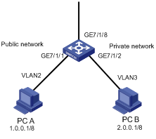
Figure 6-1 Network diagram for reflexive ACL configuration
III. Configuration procedure
# Define an EACL rule containing reflective.
<H3C> system-view
[H3C] acl number 3001
[H3C-acl-adv-3001] rule 0 permit udp reflective
[H3C-acl-adv-3001] rule permit tcp reflective
[H3C-acl-adv-3001] rule permit icmp reflective
[H3C-acl-adv-3001] quit
# Configure a reflexive ACL in VLAN 40.
[H3C] vlan 40
[H3C-vlan40] packet-filter outbound ip-group 3001 slot 5
[H3C-vlan40] quit
# Define an ACL rule used for port redirection.
[H3C] acl number 3002
[H3C-acl-adv-3002] rule 0 permit udp
[H3C-acl-adv-3002] rule permit tcp
[H3C-acl-adv-3002] rule permit icmp
[H3C-acl-adv-3002] quit
# Configure the redirection command on the port in VLAN 40.
[H3C] interface GigabitEthernet 7/1/1
[H3C-GigabitEthernet7/1/1] traffic-redirect inbound ip-group 3002 slot 5 designated-vlan 40
6.3.2 EACL BT Rate Limit Configuration Example
I. Network requirements
BitTorrent (BT) is a shareware used to download files. The feature is that the more users are downloading the same file using BT simultaneously, the faster the download speed is. BT download reduces load of the download server greatly, but it also causes an increasing amount of data on the network. As a result, network bandwidth is occupied by a great amount of BT download traffic affecting other network services seriously. To solve this problem, you must control BT traffic effectively.
In this example, you can restrict certain BT data packets to pass the service processor board by configuring proper ACL and its rule.
![]() Caution:
Caution:
BT rate limit can be configured only at the outbound direction of the NAM service processing board.
II. Network diagram
Figure 6-2 Network diagram for EACL BT rate limit configuration
III. Configuration procedure
# Define the EACL rule with bt-flag.
<H3C> system-view
[H3C] acl number 3000
[H3C-acl-adv-3000] rule permit tcp bt-flag
[H3C-acl-adv-3000] quit
# Define rate limit parameters.
[H3C] traffic-params 1 cir 1000 cbs 2000 ebs 2000
# Configure BT rate limit in VLAN 40.
[H3C] vlan 40
[H3C-vlan40] traffic-limit outbound ip-group 3000 rule 0 tc-index 1 traffic-index 1 exceed drop slot 5
# Define an ACL rule used for port redirection.
[H3C] acl number 3002
[H3C-acl-adv-3002] rule 0 permit tcp
# Configure the redirection command on the port in VLAN 40.
[H3C] interface GigabitEthernet 7/1/1
[H3C-GigabitEthernet7/1/1] traffic-redirect inbound ip-group 3002 slot 5 designated-vlan 40
Chapter 7 Global ACL Configuration
When configuring global ACL, go to these sections for information you are interested in:
l Global ACL Configuration Example
7.1 Global ACL Overview
Global ACL is a board-based function, which enables you to conveniently manage your network. With global ACL, you can apply an ACL to a board to control the traffic on all ports of the board, without the need of applying the ACL to individual ports on the board one by one. This saves resources and takes convenience to you.
& Note:
l In matching, globally configured ACL rules take precedence over the ACL rules configured on a port or VLAN.
l Any interface board with C, CA, CB, DA, DB, or DC suffix in its name supports the global ACL function.
l The OAP module does not support globally ACL configuration.
l The S9500 series routing switches do not support global ACL configuration on boards configured with cross-board link aggregation.
l If a user-defined flow template is used for global ACL, you need to apply the template both globally and on the ports where global ACL rules will be applied; otherwise, global ACL configuration may not take effect. If the default flow template is used, you need not to apply the flow template to ports.
l For the S9502, if you replace the interface board in slot 1 with a main control board, the global ACL rules originally applied to the interface board will be deleted after primary/secondary switchover.
7.2 Global ACL Configuration
Follow these steps to configure global ACL:
|
To do... |
Use the command... |
Remarks |
|
Enter system view |
system-view |
— |
|
Create an ACL and enter its view |
acl { number acl-number | name acl-name [ advanced | basic | link ] } [ match-order { config | auto } ] |
— |
|
Define an ACL rule |
rule |
Required |
|
Return to system view |
quit |
— |
|
Define a flow template |
flow-template user-defined slot slot-id template-info |
Optional |
|
Apply the user-defined flow template on a board globally |
flow-template user-defined global slot slot-id |
Optional |
|
Configure the maximum number of global ACL entries allowed on a D-type board |
global-acl maximum max-entry-num slot slot-id |
Optional 1024 by default |
|
Apply an ACL/ACL rule globally for packet filtering |
packet-filter inbound ip-group { acl-number | acl-name } [ rule rule [ system-index index ] ] slot slot-id |
Optional |
|
Apply an ACL/ACL rule globally for traffic policing |
traffic-limit inbound ip-group { acl-number | acl-name } [ rule rule [ system-index index ] ] [ tc-index index ] cir cbs ebs [ pir ] [ conform { { remark-cos | remark-drop-priority } * | remark-policed-service } ] [ exceed { forward | drop } ] slot slot-id |
Optional |
|
Display global ACL configuration |
display acl global slot slot-id |
Available in any view |
![]() Caution:
Caution:
l The global-acl maximum slot command applies to only D-type interface boards. Additionally, to make the command take effect, you must restart the interface board after configuring the command.
l Without the global-acl maximum slot command, a D-type board supports up to 1024 hardware ACL entries, including global ACLs, port ACLs, and VLAN ACLs. With the command configured, the maximum number of hardware ACL entries supported on the board is 2048 minus the number specified for the max-entry-num argument, including global ACLs, port ACLs, and VLAN-ACLs. Among them, the maximum number of global ACLs can be the one specified by max-entry-num, and the maximum number of port ACLs and VLAN-ACLs is 2048 minus two times max-entry-num.
l With the global-acl maximum slot command configured, the total number of port ACLs and VLAN-ACLs decreases. Therefore, some port ACL entries and VLAN-ACL entries may be lost after the board restarts.
7.3 Global ACL Configuration Example
I. Network requirements
As shown in Figure 7-1,
l A company uses VLANs to isolate its two departments. The R&D department belongs to VLAN 10 and on the network segment 10.10.10.0/24. The HR department belongs to VLAN 11 and on the network segment 10.11.11.0/24.
l The PCs of the R&D department are connected to GigabitEthernet 2/1/1 through GigabitEthernet 2/1/4 of the switch; the PCs of the HR department are connected to GigabitEthernet 3/1/1 through GigabitEthernet 3/1/5 of the switch.
l The HR department has a salary server, whose IP address is 10.11.11.11/24.
Configure ACLs to prevent all the PCs (except the PCs with IP addresses 10.10.10.2/24 and 10.10.10.3/24) of the R&D department from accessing the salary server from 8:00 to 18:00 during working days.
II. Network diagram
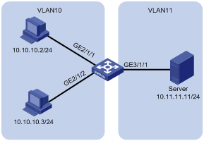
Figure 7-1 Network diagram for global ACL configuration
III. Configuration procedure
& Note:
Only the commands related to the ACL configuration are listed below.
# Create a time range worktime covering the period from 8:00 to 18:00 during working days.
<H3C> system-view
[H3C] time-range worktime 8:00 to 18:00 working-day
# Create and configure VLAN 10 and VLAN 11. Create VLAN interface 10 and VLAN interface 11, and configure proper IP addresses for them, enabling PCs of the R&D department to access the salary server of the HR department.
[H3C] vlan 10
[H3C-vlan10] port GigabitEthernet 2/1/1 to GigabitEthernet 2/1/4
[H3C-vlan10] quit
[H3C] interface Vlan-interface 10
[H3C-Vlan-interface10] ip address 10.10.10.1 255.255.255.0
[H3C-Vlan-interface10] quit
[H3C] vlan 11
[H3C-vlan11] port GigabitEthernet 3/1/1 to GigabitEthernet 3/1/5
[H3C-vlan11] quit
[H3C] interface Vlan-interface 11
[H3C-Vlan-interface11] ip address 10.11.11.1 255.255.255.0
[H3C-Vlan-interface11] quit
# Create and configure ACL 3000.
[H3C] acl number 3000
[H3C-acl-adv-3000] rule 0 permit ip source 10.10.10.2 0
[H3C-acl-adv-3000] rule 1 permit ip source 10.10.10.3 0
[H3C-acl-adv-3000] rule 2 deny ip source 10.10.10.0 0.0.0.255 destination 10.11.11.11 0 time-range worktime
[H3C-acl-adv-3000] quit
# Define a global flow template and apply it.
[H3C] flow-template user-defined slot 2 sip 0.0.0.0 dip 0.0.0.0
[H3C] flow-template user-defined global slot 2
# Apply ACL 3000 to the board in slot 2 for packet filtering.
[H3C] packet-filter inbound ip-group 3000 slot 2
# Apply the user-defined flow template to GigabitEthernet 2/1/1 through GigabitEthernet 2/1/4.
[H3C] interface GigabitEthernet 2/1/1
[H3C-GigabitEthernet2/1/1] flow-template user-defined
[H3C-GigabitEthernet2/1/1] quit
[H3C] interface GigabitEthernet 2/1/2
[H3C-GigabitEthernet2/1/2] flow-template user-defined
[H3C-GigabitEthernet2/1/2] quit
[H3C] interface GigabitEthernet 2/1/3
[H3C-GigabitEthernet2/1/3] flow-template user-defined
[H3C-GigabitEthernet2/1/3] quit
[H3C] interface GigabitEthernet 2/1/4
[H3C-GigabitEthernet2/1/4] flow-template user-defined
Chapter 8 WAN-ACL Configuration
When configuring WAN-ACL, go to these sections for information you are interested in:
l Overview
l WAN-ACL Configuration Example
8.1 Overview
A WAN-ACL refers to an ACL applied to WAN interfaces. You can configure QACL actions on a WAN interface to implement access control for the WAN interface. WAN interfaces supporting WAN-ACL include channelized interfaces or MP-group interfaces on CPOS and E1/T1 boards and ATM interfaces/subinterfaces operating in IPoA mode.
8.2 Configuring WAN-ACL
Follow these steps to configure WAN-ACL:
|
To do… |
Use the command… |
Remarks |
|
Enter system view |
system-view |
— |
|
Create an ACL and enter the ACL view |
acl { number acl-number | name acl-name [ advanced | basic | link ] } [ match-order { config | auto } ] |
Required |
|
Define ACL rules for the ACL |
rule |
Required You can configure ingress source-vlan-range in a Layer-2 ACL. However, the configuration does not take effect. |
|
Exit to system view |
quit |
— |
|
Enter WAN interface view |
interface interface-type interface-number |
The WAN interface can be a channelized interfaces or MP-group interfaces on a CPOS or E1/T1 board, or an ATM interface/subinterface operating in IPoA mode. |
|
Configure packet filtering |
packet-filter inbound ip-group { acl-number | acl-name } [ rule rule [ system-index index ] ] |
Optional |
|
Configure traffic policing |
traffic-limit inbound ip-group { acl-number | acl-name } [ rule rule [ system-index index ] ] [ tc-index index ] cir cbs ebs [ pir ] [ conform { { remark-cos | remark-drop-priority } * | remark-policed-service } ] [ exceed { forward | drop } ] |
Optional |
|
Configure priority marking |
traffic-priority inbound ip-group { acl-number | acl-name } [ rule rule [ system-index index ] ] { auto | remark-policed-service { trust-dscp | dscp dscp-value | untrusted dscp dscp-value cos cos-value local-precedence local-precedence drop-priority drop-level } } |
Optional |
|
Configure traffic redirecting |
traffic-redirect inbound ip-group { acl-number | acl-name } [ rule rule [ system-index index ] ] { cpu | next-hop ip-addr1 [ ip-addr2 ] [ invalid { forward | drop } ] | slot slot-id [ designated-vlan vlanid ] } |
Optional In WAN interface view, traffic can be redirected to the next hop, a L3+ board, or CPU; the keywords nested-vlan and modified-vlan are not supported. |
|
Configuring traffic mirroring |
mirrored-to inbound ip-group { acl-number | acl-name } [ rule rule [ system-index index ] ] cpu |
Optional |
|
Configure traffic accounting |
traffic-statistic inbound ip-group { acl-number | acl-name } [ rule rule [ system-index index ] ] [ tc-index index ] |
Optional |
|
Exit to system view |
quit |
— |
|
Display traffic mirroring information on the specified or all WAN interfaces |
display qos-interface [ interface-type interface-number ] mirrored-to |
Available in any view |
|
Display rate limiting information on the specified or all WAN interfaces |
display qos-interface [ interface-type interface-number ] traffic-limit |
|
|
Display priority marking information on the specified or all WAN interfaces |
display qos-interface [ interface-type interface-number ] traffic-priority |
|
|
Display traffic redirecting information on the specified or all WAN interfaces |
display qos-interface [ interface-type interface-number ] traffic-redirect |
|
|
Display traffic accounting information on the specified or all WAN interfaces |
display qos-interface traffic-statistic |
|
|
Display traffic rate statistics for the specified or all WAN interfaces |
display qos-interface interface-type interface-number traffic-statistic rate [ timeinterval ] |
|
|
Display packet filtering information on the specified or all WAN interfaces |
display acl running-packet-filter |
WAN-ACL configuration has the following restrictions:
l WAN-ACL only supports ACLs based on the default flow template. For a WAN-ACL to be applied successfully, you must ensure that the ACL rules contain only the fields defined in the default flow template.
l WAN-ACL does not support MPLS intermixing or selective QinQ.
l For traffic redirecting, WAN-ACL only supports redirecting traffic to CPU.
l An ATM interface/subinterface operating in EoA mode does not support WAN-ACL. If you have applied a global ACL or VLAN-ACL (the EoA interface and one or multiple Ethernet ports on the ATM board belong to the VLAN) on an ATM board, the EoA interface can match the global ACL or VLAN-ACL.
l If a WAN-ACL and a global ACL are applied at the same time, traffic will be matched against the global ACL preferentially. If the global ACL is matched, the WAN-ACL will not be matched.
8.3 WAN-ACL Configuration Example
I. Network requirements
As shown in Figure 8-1, use an E1 cable to connect an E1 interface of Switch A and an E1 interface of Switch B. Bundle timeslots 1 to 31 into a channel, and connect the two devices using PPP. Switch B uses the clock of Switch A for reference. Switch B is connected to the salary server. Configure WAN-ACL to prevent the traffic from Serial 8/1/1.1 from accessing the salary server during the working time.
II. Network diagram
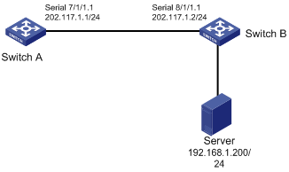
Figure 8-1 Network diagram for WAN-ACL configuration
III. Configuration procedure
1) Configuration on Switch A
# Configure interface E1 7/1/1.
<H3C> system-view
[H3C] controller e1 7/1/1
[H3C-E17/1/1] clock master
[H3C-E17/1/1] channel-set 1 timeslot-list 1-31
[H3C] interface serial 7/1/1:1
[H3C-Serial7/1/1:1] ip address 202.117.1.1 24
2) Configuration on Switch B
# Configure interface E1 8/1/1.
<H3C> system-view
[H3C] controller E1 8/1/1
[H3C-E18/1/1] clock slave
[H3C-E18/1/1] channel-set 1 timeslot-list 1-31
[H3C] interface serial 8/1/1:1
[H3C-Serial8/1/1:1] ip address 202.117.1.2 24
[H3C-Serial8/1/1:1] quit
[H3C] time-range test 8:00 to 18:00 daily
[H3C] acl number 3000
[H3C-acl-adv-3000] rule deny ip source any destination 192.168.1.200 0.0.0.0 time-range test
[H3C-acl-adv-3000] quit
[H3C] interface serial 8/1/1:1
[H3C-Serial8/1/1:1] packet-filter inbound ip-group 3000 rule 0
[H3C-Serial8/1/1:1] quit