- Table of Contents
- Related Documents
-
| Title | Size | Download |
|---|---|---|
| 02-ACL Configuration | 143.69 KB |
1.1.1 ACLs activated directly on hardware
1.1.2 ACLs referenced by upper-level modules
1.1.3 ACLs Supported on Your Device
1.2 ACL Configuration Task List
1.2.2 Configuring a Time Range
1.2.3 Defining and Applying a Flow Template
1.3 Displaying and Maintaining ACL Configuration
1.4 ACL Configuration Examples
1.4.1 Basic ACL Configuration Example
1.4.2 Advanced ACL Configuration Example
1.4.3 Configuration Example of Layer 2 ACL for Filtering by MAC Address
1.4.4 Configuration Example of Layer 2 ACL for Filtering ARP Packets
1.4.5 Example of BT Traffic Control Configuration
Chapter 1 ACL Configuration
When Configuring ACLs, go to these sections for information you are interested in:
l Displaying and Maintaining ACL Configuration
1.1 ACL Overview
Access Control Lists (ACLs) are used to filter packets passing through network devices. ACLs achieve this through ACL rules defined in them. ACL rules identify specific packets and then deny/permit the packets.
ACL rules defined in an ACL can classify packets by source/destination address and source/destination port number. After you apply an ACL globally or on a port, the device checks the received packets and denies/permits the matching packets according to the ACL rules defined in the ACL.
The rules defined in ACLs can also be used for traffic classification, for example, QoS traffic classification.
An ACL can contain multiple rules, which may be defined for packets within different address ranges. Matching order is involved in matching an ACL.
1.1.1 ACLs activated directly on hardware
ACLs can be delivered to hardware for traffic filtering and classification.
The cases when ACLs are sent directly to hardware include: referencing ACLs to provide for QoS functions, filtering and forwarding packets with ACLs.
1.1.2 ACLs referenced by upper-level modules
ACLs may also be used to filter and classify packets processed by software. In this case, you can define the order in which the rules in an ACL are matched. Two matching modes are available in this case: config (the order in which the rules are defined) and auto (depth first). You cannot modify the matching order once you define it for an ACL rule, unless you delete the rule and redefine the matching order.
The cases when ACLs are referenced by upper-level modules include referencing ACLs to achieve routing policies, and using ACLs to control register users and so on.
& Note:
l Depth first principle means putting the statement with smaller packet range in the front. You can know the packet range by comparing IP address wildcards: The smaller the wildcard is, the smaller host range is. For example, the address 129.102.1.1 0.0.0.0 specifies the host 129.102.1.1 and address 129.102.1.1 0.0.255.255 specifies the segment 129.102.1.1 to 129.102.255.255. Then 129.102.1.1 is surely put in the front. Specifically, for the statements of basic ACL rules, directly compare the wildcards of source addresses and follow config order if the wildcards are equal; for the ACL rules used in port packet filtering, the rules configured with any are put to the end and other rules follow config order; for advanced ACL rules, first compare the wildcards of source addresses, then the wildcards of destination addresses if those of source addresses are equal, then the port IDs if the wildcards of destination addresses are still equal. Follow config order if port IDs are also equal.
l The user-defined ACL matching order takes effect only when multiple rules of an ACL are applied at the same time. For example, for an ACL containing two rules, if the two rules are not applied simultaneously, even if you configure the matching order to be depth first, the switch still matches them according to the order in which they are applied.
l If one rule is a subset of another rule in an ACL, it is recommended to apply the rules according to the range of the specified packets. The rule with the smallest range of the specified data packets is applied first, and then other rules are applied based on this principle.
1.1.3 ACLs Supported on Your Device
The switch supports the following types of ACLs:
l Number-based basic ACLs
l Name-based basic ACLs
l Number-based advanced ACLs
l Name-based advanced ACLs
l Number-based Layer 2 ACLs
l Name-based Layer 2 ACLs
The limits for the ACLs on the switch are listed in the following table.
Table 1-1 Limits on ACLs on the switch
|
Item |
Number range |
Maximum number |
|
Number-based basic ACL |
2000 to 2999 |
1000 |
|
Number-based advanced ACL |
3000 to 3999 |
1000 |
|
Number-based Layer 2 ACL |
4000 to 4999 |
1000 |
|
Name-based basic ACL |
— |
— |
|
Name-based advanced ACL |
— |
— |
|
Name-based Layer 2 ACL |
— |
— |
|
Maximum rules for an ACL |
0 to 127 |
128 |
|
Maximum rules for the system |
— |
12288 |
Table 1-2 Limits on the ACL rules that can be activated on different interface cards
|
Interface card suffix |
MPLS support |
Max number of ACL rules supported by each card/port |
|
B |
MPLS not supported |
1024 |
|
DA |
||
|
DB |
||
|
DC |
||
|
C |
MPLS supported |
1023 |
|
CA |
||
|
CB |
A maximum of 1024 ACL rules can be activated on a service processor card.
& Note:
The suffix of the card can be identified through the silkscreen on the upper-right corner of the front panel of the card. For example, the silkscreen of the LSBGP12B0 is GP12B, so the suffix of the card is B.
1.2 ACL Configuration Task List
Complete the following tasks to perform ACL configuration:
l Defining and Applying a Flow Template
1.2.1 Configuring an ACL
Follow these steps to configure an ACL for an interface card:
|
Use the command… |
Remarks |
|
|
Enter system view |
system-view |
— |
|
Configure a time range |
time-range time-name { { start-time to end-time days-of-the-week [ from start-time start-date ] [ to end-time end-date ] } | { from start-time start-date [ to end-time end-date ] } | { to end-time end-date } } |
Optional |
|
Define a flow template |
flow-template user-defined slot slot-id template-info |
Optional |
|
Enter ACL view |
acl { number acl-number | name acl-name [ advanced | basic | link ] } [ match-order { config | auto } ] |
Required |
|
Define a rule |
rule |
Required |
|
Exit ACL view |
quit |
— |
|
Enter Ethernet port view |
interface interface-type interface-number |
The value of interface-type can only be Ethernet port type. |
|
Apply a flow template in Ethernet port view |
flow-template user-defined |
Optional You can perform this operation only when a flow template has been previously defined. |
|
Activate the ACL |
packet-filter inbound |
Required |
Follow these steps to configure an ACL configuration for a service processor card:
|
Use the command… |
Remarks |
|
|
Enter system view |
system-view |
— |
|
Configure a time range |
time-range time-name { start-time to end-time days-of-the-week [ from start-time start-date ] [ to end-time end-date ] | from start-time start-date [ to end-time end-date ] | to end-time end-date } |
Optional |
|
Enter ACL view |
acl { number acl-number | name acl-name [ advanced | basic | link] } [ match-order { config | auto } ] |
Required Service processor cards do not support Layer 2 ACL. |
|
Define a rule |
rule |
Required |
|
Exit ACL view |
quit |
— |
|
Enter Ethernet port view |
interface interface-type interface-number |
— |
|
Configure traffic redirection in Ethernet port view to redirect the packets of a specific VLAN to a service processor card |
traffic-redirect inbound ip-group |
Required Refer to Configuring Traffic Redirection in QoS Configuration. |
|
Exit Ethernet port view |
quit |
— |
|
Enter VLAN view |
vlan vlan-id |
You must enter the VLAN view specified by the redirection function. |
|
Activate the ACL in VLAN view |
packet-filter inbound ip-group { acl-number | acl-name } [ rule rule [ system-index index ] ] slot slot-id |
Required |
1.2.2 Configuring a Time Range
There are two types of time ranges:
l Periodic time range, in the form of week days.
l Absolute time range, defined by specifying the starting time/date and the end time/date.
Perform the following configurations in system view to configure/remove a time range:
|
To do... |
Use the command... |
|
Create a time range |
time-range time-name { start-time to end-time days-of-the-week [ from start-time start-date ] [ to end-time end-date ] | from start-time start-date [ to end-time end-date ] | to end-time end-date } |
|
Remove a time range |
undo time-range { time-name [ start-time to end-time days-of-the-week [ from start-time start-date ] [ to end-time end-date ] | from start-time start-date [ to end-time end-date ] | to end-time end-date ] | all } |
In the above table, the start-time argument along with the end-time days-of-the-week argument specifies a periodic time range; the start-time start-date argument along with the end-time end-date argument specifies an absolute time range.
For time ranges containing only one type of time segments,
l A time range containing only one periodic time segment is active when the system time is within the periodic time segment.
l A time range containing multiple periodic time segments is active when the system is within one of the periodic time segments.
l A time range containing one absolute time segment is active when the system time is within the absolute time segment.
l A time range containing multiple absolute time segments is active when the system time is within one of the absolute time segments.
For time ranges containing both types of time segments:
l A time range containing a periodic time segment and an absolute time segment is active when the system time is within the periodic time segment and the absolute time segment. For example, assuming that a time range contains a periodic time segment which is from 12:00 to 14:00 every Wednesday and an absolute time range which is from 00:00 2004/1/1 to 23:59 2004/12/31, the time range is active when the system time is within 12:00 to 14:00 every Wednesday in 2004.
l A time range containing multiple absolute time segments and multiple periodic time segments is active when the system time is within one of the absolute time segments and one of the periodic time segments.
& Note:
l You cannot configure multiple periodic time segments and multiple absolute time segments for the same time range at a time. To configure multiple absolute/periodic time segments for a time range, you need to execute the time-range command repeatedly, with the time-name argument being the same.
l If neither starting time nor end time is specified, the time range is 24 hours (00:00 to 24:00).
l If no end date is specified, the time range is from the date of configuration till the largest date available in the system (currently the largest time range is 1970/01/01 to 2100/12/31 in the system).
1.2.3 Defining and Applying a Flow Template
Flow template is used for traffic classification. It specifies the rules according to which traffic classification is performed. For example, with a template defining a quadruple containing source IP address, destination IP, source TCP port, and destination TCP ports applied, only those traffic classification rules containing all these elements can be applied to hardware for QoS-related functions (such as packet filtering, traffic policing, and priority marking). Other rules cannot be activated on the hardware and referenced.
Perform the following configurations in system view to define/remove a flow template:
|
To do... |
Use the command... |
|
Define a flow template |
flow-template user-defined slot slot-id template-info |
|
Remove a flow template |
undo flow-template user-defined slot slot-id |
Note that the total size of all the elements cannot be larger than 16 bytes. The following table lists the length of the elements involved.
Table 1-3 Length of flow template elements
|
Name |
Description |
Length in template |
|
bt-flag |
BT flag bit |
6 bytes |
|
Cos |
The 802.1p priority in the most external 802.1QTag carried by the packet |
For cards suffixed with DA/DB/DC, the s-tag-vlan field is two bytes in length; the Cos is one byte in length. For other types of cards, the total length of the s-tag-vlan field and the Cos field is two bytes in length no matter whether or not they are all defined. |
|
s-tag-vlan |
VLAN ID in the most exterior 802.1QTag carried by the packet |
|
|
Dip |
Destination IP field in IP packet header |
4 bytes |
|
Dmac |
Destination MAC field in Ethernet packet header |
6 bytes |
|
Dport |
Destination port field |
2 bytes |
|
Dscp |
DSCP field in IP packet header |
1 byte |
|
ip-precedence |
IP precedence field in IP packet header |
|
|
tos |
ToS field in IP packet header |
|
|
exp |
EXP field in MPLS packet |
|
|
ethernet-protocol |
Protocol field in Ethernet packet header |
6 bytes |
|
fragment-flags |
Flag field of fragment in IP packed header |
No bytes |
|
icmp-code |
ICMP code field |
1 byte |
|
icmp-type |
ICMP type field |
1 byte |
|
mac-type |
MAC-TYPE field in the packet |
No bytes |
|
c-tag-cos |
The 802.1p priority in the internal 802.1QTag carried by the packet |
6 bytes |
|
c-tag-vlan |
The VLAN ID in the internal 802.1QTag carried by the packet |
|
|
ip-protocol |
Protocol field in IP packet header |
1 byte |
|
sip |
Source IP field in IP packet header |
4 bytes |
|
smac |
MAC field in Ethernet packet header |
6 bytes |
|
sport |
Source port field |
2 bytes |
|
tcp-flag |
Flag field in TCP packet header |
1 byte |
|
vlanid |
Vlan ID that the switch assigns to the packet |
2 bytes |
|
vpn |
The flow template pre-defined for MPLS2VPN |
2 bytes |
|
ttl |
Time to live of packet |
1 byte |
& Note:
l The numbers listed in the table are not the actual length of these elements in IP packets, but their length in flow template. DSCP field is one byte in flow template, but six bits in IP packets. You can determine whether the total length of template elements exceeds 16 bytes using these numbers.
l The dscp, exp, ip-precedence, and tos fields jointly occupy one byte. One byte is occupied no matter you define one, two or three of these fields.
l The c-tag-cos and c-tag-vlanid fields jointly occupy six bytes. Six bytes are occupied no matter you define one or both of them.
l The fragment-flags and mac-type fields do not occupy the length of flow template, so you need not take them into account when determining whether the total length of template elements exceeds 16 bytes.
l C-type cards with 100 Mbps ports do not support the mac-type field.
l If you configure QoS and ACL to prevent TTL=1 IP packet attacks, your configuration will filter out some IP packets with TTL of 1. In this case, to permit expected TTL=1 packets to reach up to the CPU, you need to add some rules in your ACL.
l To apply the user-defined flow template to a VLL-enabled port, make sure the flow template includes the vlanid field. (VLL: virtual leased line.)
Usually, you can either use the default template or define a flow template based on your needs.
![]() Caution:
Caution:
An OAP card supports only the default template.
& Note:
l Currently, the default flow template is ip-protocol, tcp-flag sport dport icmp-type icmp-code sip 0.0.0.0 dip 0.0.0.0 ethernet-protocol vlanid exp, among which the ethernet-protocol field does not occupy spaces in IP sub-flow template. This field aims to simplify the configuration of the actions concerning ARP packets. You can apply ACLs with ethernet-protocol filed directly when the default flow template is adopted.
l Support for Layer 2 ACLs matching the combination of the source MAC address field and the packet type (except the 0x0800, 0x8847, 0x8848, and 0x86dd type) is added to the default flow template. But the default flow template does not support a Layer 2 ACL with only the source MAC address specified. For related information, refer to Configuration Example of Layer 2 ACL for Filtering ARP Packets.
You cannot modify or delete the default flow template.
Perform the following configuration in Ethernet port view to apply/cancel a flow template:
|
To do... |
Use the command... |
|
Apply the user-defined flow template |
flow-template user-defined |
|
Cancel the applied flow template |
undo flow-template user-defined |
1.2.4 Defining an ACL
The switch supports several types of ACLs, which are described in this section.
Follow these steps to define an ACL:
1) Enter ACL view
2) Define ACL rules
& Note:
l If the time-range keyword is not selected, the ACL will be effective at any time after being activated.
l You can define multiple rules for an ACL by executing the rule command repeatedly.
l When the QoS/ACL action is configured under the port, if the QoS/ACL is applied without sub rules, the QoS/ACL is matched as per the matching order defined in the ACL rule; if applied with specific sub rules, the QoS/ACL is matched as per the sequence applied under the port.
l By default, ACL rules are matched in config order.
l If you want to replace an existing rule, you are recommended to use the undo command to delete the original rule first and then reconfigure the rule.
I. Defining a basic ACL
Basic ACLs only make rules and process packets according to the source IP addresses.
Perform the following configurations in the specified views to define/remove a basic ACL:
|
To do... |
Use the command... |
|
Enter basic ACL view (from system view) |
acl { number acl-number | name acl-name basic } [ match-order { config | auto } ] |
|
Define an ACL rule (in basic ACL view) |
rule [ rule-id ] { permit | deny } [ packet-level { bridge | route } | source { source-addr wildcard | any } | fragment | time-range name | vpn-instance instance-name ] * |
|
Remove an ACL rule (in basic ACL view) |
undo rule rule-id [ packet-level | source | fragment | time-range | vpn-instance instance-name ] * |
|
Remove an ACL or all ACLs (in system view) |
undo acl { number acl-number | name acl-name | all } |
II. Defining an advanced ACL
Advanced ACLs define classification rules and process packets according to the attributes of the packets such as source and destination IP addresses, TCP/UDP ports used, and packet priority. ACLs support three types of priority schemes: ToS (type of service) priority, IP priority and DSCP priority.
Perform the following configurations in the specified view to define/remove an advanced ACL:
|
To do... |
Use the command... |
|
Enter advanced ACL view (from system view) |
acl { number acl-number | name acl-name advanced } [ match-order { config | auto } ] |
|
Define an ACL rule (in advanced ACL view) |
rule [ rule-id ] { permit | deny } protocol [ packet-level { bridge | route } | source { source-addr wildcard | any } | destination { dest-addr wildcard | any } | source-port operator port1 [ port2 ] | destination-port operator port1 [ port2 ] | icmp-type type code | established | { match-any | match-all } { urg | ack | psh | rst | syn | fin } | precedence precedence | tos tos | dscp dscp | fragment | bt-flag | time-range name | vpn-instance instance-name | ttl ttl-value ] * |
|
Remove an ACL rule (in advanced ACL view) |
undo rule rule-id [ packet-level | source | destination | source-port | destination-port | icmp-type | precedence | tos | dscp | fragment | bt-flag | time-range | vpn-instance | ttl ] * |
|
Remove an ACL or all ACLs (in system view) |
undo acl { number acl-number | name acl-name | all } |
![]() Caution:
Caution:
l The port1 and port2 argument in the command listed in the above table should be TCP/UDP ports for higher-layer applications. For some common ports, you can use mnemonic symbols to replace the corresponding port numbers. For example, you can use bgp to represent TCP port 179, which is for BGP protocol.
l If a certain advanced ACL has been occupied by IDS, you cannot modify or remove it through commands.
l The rules with specified bt-flag cannot be used in the traffic-redirect command.
III. Defining a Layer 2 ACL
Layer 2 ACLs define the Layer 2 information such as source and destination MAC addresses, source VLAN ID, and Layer 2 protocol type in their rules and process packets according to these attributes.
Perform the following configurations in the specified view to define/remove a Layer 2 ACL:
|
To do... |
Use the command... |
|
Enter Layer 2 ACL view (from system view) |
acl { number acl-number | name acl-name link } [ match-order { config | auto } ] |
|
Define an ACL rule (in Layer 2 ACL view) |
rule [ rule-id ] { permit | deny } [ packet-level { bridge | route } | cos cos-value | c-tag-cos c-cos-value | exp exp-value | protocol-type | mac-type { any-broadcast-packet | arp-broadcast-packet | non-arp-broadcast-packet | { { unicast-packet | multicast-packet } [ known | unknown ] } } | ingress { { source-vlan-id [ to source-vlan-id-end ] | source-mac-addr source-mac-wildcard | c-tag-vlan c-tag-vlan } * | any } | egress { dest-mac-addr dest-mac-wildcard | any } | s-tag-vlan s-tag-vlanid | time-range name ] * |
|
Remove an ACL rule (in Layer 2 ACL view) |
undo rule rule-id |
|
Remove an ACL or all the ACLs (in system view) |
undo acl { number acl-number | name acl-name | all } |
1.2.5 Activating an ACL
After defining an ACL, you must activate it for it to take effect. This configuration activates those ACLs to filter or classify the packets forwarded by hardware.
For interface cards, perform the following configurations in Ethernet port view to activate/deactivate an ACL:
|
To do... |
Use the command... |
|
Activate IP group ACL |
packet-filter inbound ip-group { acl-number | acl-name } [ rule rule [ system-index index ] ] |
|
Deactivate IP group ACL |
undo packet-filter inbound ip-group { acl-number | acl-name } [ rule rule ] |
|
Activate IP group ACL and link group ACL at same time |
packet-filter inbound ip-group { acl-number | acl-name } { rule rule link-group { acl-number | acl-name } [ rule rule [ system-index index ] ] | link-group { acl-number | acl-name } rule rule } |
|
Deactivate IP group ACL and link group ACL at same time |
undo packet-filter inbound ip-group { acl-number | acl-name } { rule rule link-group { acl-number | acl-name } [ rule rule ] | link-group { acl-number | acl-name } rule rule } |
|
Activate link group ACL |
packet-filter inbound link-group { acl-number | acl-name } [ rule rule [ system-index index ] ] |
|
Deactivate link group ACL |
undo packet-filter inbound link-group { acl-number | acl-name } [ rule rule ] |
For service processor cards, perform the following configurations in VLAN view to activate ACL:
|
To do... |
Use the command... |
|
Activate IP group ACL |
packet-filter inbound ip-group { acl-number | acl-name } [ rule rule [ system-index index ] ] slot slot-id |
|
Deactivate IP group ACL |
undo packet-filter inbound ip-group { acl-number | acl-name } [ rule rule ] slot slot-id |
![]() Caution:
Caution:
l The syntax of the QoS ACL command used for service processor cards (LSB1NATB0 cards in the context of this document) is somewhat different from that for interface cards. Refer to related description in the manual.
l Before executing the packet-filter command on a service processor card, you must first configure traffic redirection in Ethernet port view to redirect the packets of a specific VLAN to the service processor card.
l Service processor cards do not support Layer 2 ACL.
system-index index here is the system index for an ACL rule. When delivering a rule, the system assigns a globally unique index to it, for convenience of later retrieval. You can also assign a system index for it when delivering an ACL rule with this command, but the index value may change while the system is running. You are not recommended to assign a system index if not urgently necessary.
1.3 Displaying and Maintaining ACL Configuration
|
To do… |
Use the command… |
Remarks |
|
Display the configuration and status of the current time range |
display time-range { all | name } |
Available in any view |
|
Display ACL configuration |
display acl config { all | acl-number | acl-name } |
Available in any view |
|
Display the total number of ACL rules applied on the specified card |
display acl remaining entry slot slot-id |
Available in any view |
|
Display ACL application information |
display acl running-packet-filter { all | interface interface-type interface-number | vlan vlan-id } |
Available in any view |
|
Display the configuration information of the flow template |
display flow-template [ default | interface interface-type interface-number | slot slot-id | user-defined ] |
Available in any view |
|
Clear ACL statistics |
reset acl counter { all | acl-number | acl-name } |
Available in user view |
The display acl config command only displays the ACL matching information processed by the CPU.
See the corresponding Command Manual for description of parameters.
1.4 ACL Configuration Examples
1.4.1 Basic ACL Configuration Example
I. Network requirements
With proper basic ACL configuration, during the time range from 8:00 to 18:00 everyday the switch filters out the packets from the host with source IP 10.1.1.1 (the host is connected through the port Ethernet2/1/1 to the switch.)
II. Network diagram
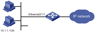
Figure 1-1 Network diagram for basic ACL configuration
III. Configuration procedure
& Note:
Only the commands concerning ACL configuration are listed here.
1) Define the time range.
# Define a time range ranging from 8:00 to 18:00.
<H3C> system-view
[H3C] time-range test 8:00 to 18:00 daily
2) Define the traffic with source IP 10.1.1.1.
# Create a name-based basic ACL named traffic-of-host.
[H3C] acl name traffic-of-host basic
# Define an ACL rule for the ACL.
[H3C-acl-basic-traffic-of-host] rule 1 deny source 10.1.1.1 0 time-range test
[H3C-acl-basic-traffic-of-host] quit
3) Activate the ACL.
# Activate the ACL.
[H3C] interface ethernet2/1/1
[H3C-Ethernet2/1/1] packet-filter inbound ip-group traffic-of-host
1.4.2 Advanced ACL Configuration Example
I. Network requirements
l A company deploys two VLANs in the intranet. The research and development (R&D) department belongs to VLAN 10 (10.10.10.0/24) and the human resource (HR) department belongs to VLAN 11 (10.11.11.0/24).
l PCs in the R&D department are connected to GigabitEthernet 2/1/1 through GigabitEthernet 2/1/4 of the switch. PCs in the HR department are connected to GigabitEthernet 3/1/1 through GE 3/1/5.
l The wage server (Server in the figure), whose IP address is 10.11.11.11/24, is in the HR department.
l The requirement is to configure an ACL to inhibit the R&D department, except for PCs 10.10.10.2/24 and 10.10.10.3/24, from accessing the wage server from 8:00 to 18:00 every working day.
II. Network diagram
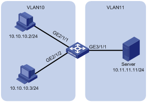
Figure 1-2 Network diagram for advanced ACL configuration
III. Configuration procedure
& Note:
Only the commands concerning ACL configuration are listed here.
1) Define the time range.
# Define a time range that is active from 8:00 to 18:00 every working day.
<H3C> system-view
[H3C] time-range worktime 8:00 to 18:00 working-day
# Create VLAN 10 and VLAN 11 on the switch and assign IP addresses to the VLAN interfaces, so that PCs in the R&D department can access the wage server in the HR department.
[H3C] vlan 10
[H3C-vlan10] port gigabitethernet 2/1/1 to gigabitethernet 2/1/4
[H3C-vlan10] quit
[H3C] interface vlan-interface 10
[H3C-Vlan-interface10] ip address 10.10.10.1 255.255.255.0
[H3C-Vlan-interface10] quit
[H3C] vlan 11
[H3C-vlan11] port gigabitethernet 3/1/1 to gigabitethernet 3/1/5
[H3C-vlan11] quit
[H3C] interface vlan-interface 11
[H3C-Vlan-interface11] ip address 10.11.11.1 255.255.255.0
[H3C-Vlan-interface11] quit
# Configure an ACL on the switch.
[H3C] acl number 3000
[H3C-acl-adv-3000] rule 0 permit ip source 10.10.10.2 0
[H3C-acl-adv-3000] rule 1 permit ip source 10.10.10.3 0
[H3C-acl-adv-3000] rule 2 deny ip source 10.10.10.0 0.0.0.255 destination 10.11.11.11 0 time-range worktime
[H3C-acl-adv-3000] quit
# Activate the ACL on the ports connected with PCs of the R&D department.
[H3C] interface gigabitethernet 2/1/1
[H3C-GigabitEthernet2/1/1] packet-filter inbound ip-group 3000
[H3C-GigabitEthernet2/1/1] quit
[H3C] interface gigabitethernet 2/1/2
[H3C-GigabitEthernet2/1/2] packet-filter inbound ip-group 3000
[H3C-GigabitEthernet2/1/2] quit
[H3C] interface gigabitethernet 2/1/3
[H3C-GigabitEthernet2/1/3] packet-filter inbound ip-group 3000
[H3C-GigabitEthernet2/1/3] quit
[H3C] interface gigabitethernet 2/1/4
[H3C-GigabitEthernet2/1/4] packet-filter inbound ip-group 3000
1.4.3 Configuration Example of Layer 2 ACL for Filtering by MAC Address
I. Network requirements
Configure port Ethernet 2/1/1 of the switch to filter packets traveling from MAC address 010A-E201-0101 to MAC address 0260-E207-0202 during the time range from 8:00 to 18:00 everyday.
II. Network diagram
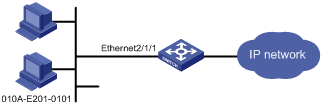
Figure 1-3 Network diagram for Layer 2 ACL configuration (filtering by MAC address)
III. Configuration procedure
& Note:
Only the commands concerning ACL configuration are listed here.
1) Define the time range.
# Define a time range that is active from 8:00 to 18:00 everyday.
<H3C> system-view
[H3C] time-range test 8:00 to 18:00 daily
2) Define a flow template.
[H3C] flow-template user-defined slot 2 ethernet-protocol smac 0-0-0 dmac 0-0-0
3) Define an ACL to filter packets traveling from MAC address 010A-E201-0101 to MAC address 0260-E207-0202.
[H3C] acl name traffic-of-link link
[H3C-acl-link-traffic-of-link] rule 1 deny ingress 010a-e201-0101 0-0-0 egress 0260-e207-0202 0-0-0 time-range test
[H3C-acl-link-traffic-of-link] quit
4) Apply the user-defined flow template to the port and activate the ACL.
# Apply the user-defined flow template to Ethernet 2/1/1.
[H3C] interface ethernet2/1/1
[H3C-Ethernet2/1/1] flow-template user-defined
# Activate the ACL named traffic-of-link.
[H3C-Ethernet2/1/1] packet-filter inbound link-group traffic-of-link
1.4.4 Configuration Example of Layer 2 ACL for Filtering ARP Packets
I. Network requirements
The switch acts as a gateway and a PC is attached to it. The PC attacks the switch by sending a large quantity of ARP packets, burdening the switch CPU.
Configure the switch to drop ARP packets from the PC. Assume that the source MAC address of the PC is 010A-E201-0101.
II. Network diagram
Figure 1-4 Network diagram for Layer 2 ACL configuration (for filtering ARP packets)
III. Configuration procedure
1) Configure a Layer 2 ACL and define the ACL rule.
<H3C> system-view
[H3C] acl number 4000
[H3C-acl-link-4000] rule 0 deny arp ingress 010a-e201-0101 0-0-0
[H3C-acl-link-4000] quit
2) Enter port view of Ethernet 2/1/1, and apply the ACL on the port.
[H3C] interface ethernet 2/1/1
[H3C-Ethernet2/1/1] packet-filter inbound link-group 4000 rule 0
1.4.5 Example of BT Traffic Control Configuration
I. Network requirements
BitTorrent (BT) is a kind of shared software for file download. Its feature is as follows: The more people are using it to download a file, the faster the file downloads. While BT download greatly reduces the burden of the download server, it also brings dramatic increase of download traffic on the internet. As a result, the network bandwidth is greatly occupied by the BT download traffic, which influences other network services seriously. Therefore, it is necessary to control the BT traffic.
The purpose of the configuration is to prohibit the BT data traffic passing through port GigabitEthernet 7/1/8 by configuring proper ACL rules.
![]() Caution:
Caution:
LSB1XP4 series cards do not support BT traffic control configuration.
Cards with suffixes DA/DB/DC do not support BT traffic control configuration.
II. Network diagram
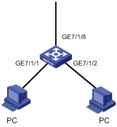
Figure 1-5 Network diagram for BT traffic control configuration
III. Configuration procedure
1) Define a user-defined flow template.
<H3C> system-view
[H3C] flow-template user-defined slot 7 ip-protocol bt-flag sip 0.0.0.0 dport
2) Define an advanced ACL.
[H3C] acl number 3000
[H3C-acl-adv-3000] rule 0 deny tcp bt-flag
[H3C-acl-adv-3000] quit
3) Enter the port GigabitEthernet 7/1/8 port view and configure BT traffic control on the port.
[H3C] interface gigabitethernet 7/1/8
[H3C-GigabitEthernet7/1/8] flow-template user-defined
[H3C-GigabitEthernet7/1/8] packet-filter inbound ip-group 3000 rule 0