- Table of Contents
- Related Documents
-
| Title | Size | Download |
|---|---|---|
| 02-QoS Configuration | 560.53 KB |
Contents
Applying QoS techniques in a network
QoS configuration approach overview
Displaying and maintaining QoS policies
Priority mapping configuration
Introduction to priority mapping
Priority mapping configuration tasks
Configuring a priority mapping table
Configuring a port to trust packet priority for priority mapping
Changing the port priority of an interface
Displaying and maintaining priority mapping
Priority mapping configuration examples
Priority mapping table configuration example
Priority mapping table and priority marking configuration example
Displaying and maintaining line rate
Line rate configuration example
Congestion management configuration·
Congestion management overview
Causes, impacts, and countermeasures
Congestion management techniques
Congestion management configuration approaches
Traffic filtering configuration
Traffic filtering configuration example
Traffic filtering configuration example
Priority marking configuration
Priority marking configuration example
Priority marking configuration example
Traffic redirecting configuration
Configuring traffic redirecting
Appendix A Default priority mapping tables
Uncolored priority mapping tables
Appendix B Introduction to packet precedences
This chapter includes these sections:
|
|
NOTE: · The term "switch" or "device" in this chapter refers to the switching engine on a WX3000E wired-wireless switch. · The WX3000E series comprises WX3024E and WX3010E wired-wireless switches. · The port numbers in this chapter are for illustration only. |
Introduction to QoS
In data communications, Quality of Service (QoS) is the ability of a network to provide differentiated service guarantees for diversified traffic in terms of bandwidth, delay, jitter, and drop rate.
Network resources are scarce. The contention for resources requires that QoS prioritize important traffic flows over trivial ones. For example, in the case of fixed bandwidth, if a traffic flow gets more bandwidth, the other traffic flows will get less bandwidth and may be affected. When making a QoS scheme, you must consider the characteristics of various applications to balance the interests of diversified users and to utilize network resources.
The following section describes some typical QoS service models and widely used, mature QoS techniques.
QoS service models
This section covers three typical QoS service models:
Best-effort service model
Best effort is a single-service model and also the simplest service model. In the best-effort service model, the network does its best to deliver packets, but does not guarantee delay or reliability.
The best-effort service model is the default model in the Internet and applies to most network applications. It uses the first in first out (FIFO) queuing mechanism.
IntServ model
The integrated service (IntServ) model is a multiple-service model that can accommodate diverse QoS requirements. It provides the most granularly differentiated QoS by identifying and guaranteeing definite QoS for each data flow.
In the IntServ model, an application must request service from the network before it sends data. IntServ signals the service request with the Resource Reservation Protocol (RSVP). All nodes receiving the request reserve resources as requested and maintain state information for the application flow.
The IntServ model demands high storage and processing capabilities because it requires all nodes along the transmission path to maintain resource state information for each flow. The model is suitable for small-sized or edge networks, but not large-sized networks, for example, the core layer of the Internet, where billions of flows are present.
DiffServ model
The differentiated service (DiffServ) model is a multiple-service model that can satisfy diverse QoS requirements. It is easy to implement and extend. DiffServ does not signal the network to reserve resources before sending data, as IntServ does.
All QoS techniques in this document are based on the DiffServ model.
QoS techniques overview
The QoS techniques include traffic classification, traffic policing, traffic shaping, line rate, congestion management, and congestion avoidance. The following sections briefly introduce these QoS techniques.
Applying QoS techniques in a network
Figure 1 Position of the QoS techniques in a network
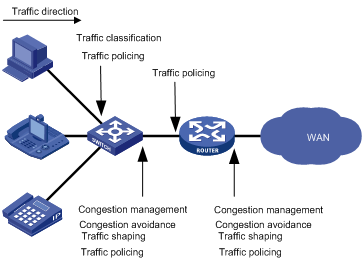
As shown in Figure 1, traffic classification, traffic shaping, traffic policing, congestion management, and congestion avoidance mainly implement the following functions:
· Traffic classification uses certain match criteria to assign packets with the same characteristics to a class. Based on classes, you can provide differentiated services.
· Traffic policing polices flows entering or leaving a device, and imposes penalties on traffic flows that exceed the pre-set threshold to prevent aggressive use of network resources. You can apply traffic policing to both incoming and outgoing traffic of a port.
· Traffic shaping proactively adapts the output rate of traffic to the network resources available on the downstream device to eliminate packet drops. Traffic shaping usually applies to the outgoing traffic of a port.
· Congestion management provides a resource scheduling policy to determine the packet forwarding sequence when congestion occurs. Congestion management usually applies to the outgoing traffic of a port.
· Congestion avoidance monitors the network resource usage, and is usually applied to the outgoing traffic of a port. When congestion worsens, congestion avoidance reduces the queue length by dropping packets.
QoS configuration approaches
This chapter includes these sections:
· QoS configuration approach overview
|
|
NOTE: · The term "switch" or "device" in this chapter refers to the switching engine on a WX3000E wired-wireless switch. · The WX3000E series comprises WX3024E and WX3010E wired-wireless switches. · The port numbers in this chapter are for illustration only. |
QoS configuration approach overview
The following approaches are available for configuring QoS: Non-policy approach and Policy approach.
Some features support both approaches, but some support only one.
Non-policy approach
In non-policy approach, you can configure QoS service parameters without using a QoS policy. For example, you can use the line rate feature to set a rate limit on an interface without using a QoS policy.
Policy approach
In policy approach, you configure QoS service parameters by using QoS policies. A QoS policy defines the shaping, policing, or other QoS actions to take on different classes of traffic. It is a set of class-behavior associations.
A class is a set of match criteria for identifying traffic, and it uses the AND or OR operator:
· If the operator is AND, a packet must match all the criteria to match the class.
· If the operator is OR, a packet matches the class if it matches any of the criteria in the class.
A traffic behavior defines a set of QoS actions to take on packets, such as priority marking and redirect.
By associating a traffic behavior with a class in a QoS policy, you apply the specific set of QoS actions to the class of traffic.
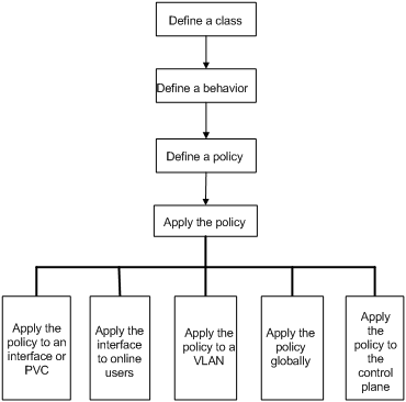
Configuring a QoS policy
Figure 2 shows how to configure a QoS policy.
Figure 2 QoS policy configuration procedure
Defining a class
To define a class, specify its name and then configure the match criteria in class view.
Follow these steps to define a class:
|
To do… |
Use the command… |
Remarks |
|
Enter system view |
system-view |
— |
|
Create a class and enter class view |
traffic classifier tcl-name [ operator { and | or } ] |
Required By default, the operator of a class is AND. The operator of a class can be AND or OR. · AND: A packet is assigned to a class only when the packet matches all the criteria in the class. · OR: A packet is assigned to a class if it matches any of the criteria in the class. |
|
Configure match criteria |
if-match match-criteria |
Required Repeat this step to configure multiple match criteria for the class. For more information, see the if-match command in the ACL and QoS Command Reference. |
Defining a traffic behavior
A traffic behavior is a set of QoS actions (such as traffic filtering, shaping, policing, and priority marking) to take on a class of traffic. To define a traffic behavior, first create it and then configure QoS actions, such as priority marking and traffic redirecting, in traffic behavior view.
Follow these steps to define a traffic behavior:
|
To do… |
Use the command… |
Remarks |
|
Enter system view |
system-view |
— |
|
Create a traffic behavior and enter traffic behavior view |
traffic behavior behavior-name |
Required |
|
Configure actions in the traffic behavior |
See the subsequent chapters, depending on the purpose of the traffic behavior: traffic policing, traffic filtering, traffic redirecting, priority marking, traffic accounting, and so on. |
|
Defining a policy
You associate a behavior with a class in a QoS policy to perform the actions defined in the behavior for the class of packets.
You cannot name a user-defined QoS policy the same as the system-defined QoS policy.
Follow these steps to associate a class with a behavior in a policy:
|
To do… |
Use the command… |
Remarks |
|
Enter system view |
system-view |
— |
|
Create a policy and enter policy view |
qos policy policy-name |
Required |
|
Associate a class with a behavior in the policy |
classifier tcl-name behavior behavior-name |
Required |
Applying the QoS policy
You can apply a QoS policy to the following occasions:
· An interface—The policy takes effect on the traffic sent or received on the interface.
· A user profile—The policy takes effect on the traffic sent or received by the online users of the user profile.
· A VLAN—The policy takes effect on the traffic sent or received on all ports in the VLAN.
· Globally—The policy takes effect on the traffic sent or received on all ports.
|
|
NOTE: You can modify classes, behaviors, and class-behavior associations in a QoS policy even after it is applied. If a class references an ACL for traffic classification, you can delete or modify the ACL (such as add rules to, delete rules from, and modify rules of the ACL). |
Applying the QoS policy to an interface
A policy can be applied to multiple interfaces, but only one policy can be applied in one direction (inbound or outbound) of an interface.
Follow these steps to apply the QoS policy to an interface:
|
To do… |
Use the command… |
Remarks |
|
|
Enter system view |
system-view |
— |
|
|
Enter interface view or port group vie, |
Enter interface view |
interface interface-type interface-number |
Use either command. Settings in interface view take effect on the current interface. Settings in port group view take effect on all ports in the port group |
|
Enter port group view |
port-group manual port-group-name |
||
|
Apply the policy to the interface or port group |
qos apply policy policy-name inbound |
Required |
|
|
|
NOTE: The QoS policy applied to the outgoing traffic on an interface does not regulate local packets, which are critical protocol packets sent by the local system for operation maintenance. The most common local packets include link maintenance, routing (IS-IS, BGP, and OSPF for example), RIP, LDP, RSVP, and SSH packets. |
Applying the QoS policy to online users
A QoS policy can be applied to multiple online users. In one direction of each online user, only one policy can be applied. To modify a QoS policy already applied in a certain direction, remove the QoS policy application first.
Follow these steps to apply the QoS policy to online users:
|
To do… |
Use the command… |
Remarks |
|
Enter system view |
system-view |
— |
|
Enter user profile view |
user-profile profile-name |
Required The configuration made in user profile view takes effect when the user-profile is activated and the users of the user profile are online. For more information about user profiles, see the Security Configuration Guide. |
|
Apply the QoS policy |
qos apply policy policy-name inbound |
Required Use the inbound keyword to apply the QoS policy to the incoming traffic of the device (traffic sent by the online users). |
|
Return to system view |
quit |
— |
|
Activate the user profile |
user-profile profile-name enable |
Required Inactive by default. |
|
|
NOTE: · You cannot modify or remove the QoS policy used by an active user profile. However, you can edit any ACL referenced by the QoS policy when the user profile has no online users. · The QoS policy applied to a user profile supports only the remark, and filter actions. · Do not apply a null policy to a user profile. The user profile using a null policy cannot be activated. · The authentication methods available for online users include 802.1X. |
Applying the QoS policy to a VLAN
You can apply a QoS policy to a VLAN to regulate traffic of the VLAN.
Follow these steps to apply the QoS policy to a VLAN:
|
To do… |
Use the command… |
Remarks |
|
Enter system view |
system-view |
— |
|
Apply the QoS policy to VLANs |
qos vlan-policy policy-name vlan vlan-id-list{ inbound |
Required |
|
|
NOTE: QoS policies cannot be applied to dynamic VLANs, for example, VLANs created by GVRP. |
Applying the QoS policy globally
You can apply a QoS policy globally to the inbound or outbound direction of all ports.
Follow these steps to apply the QoS policy globally:
|
To do… |
Use the command… |
Remarks |
|
Enter system view |
system-view |
— |
|
Apply the QoS policy globally |
qos apply policy policy-name global inbound |
Required |
Displaying and maintaining QoS policies
|
To do… |
Use the command… |
Remarks |
|
Display traffic class configuration |
display traffic classifier user-defined [ tcl-name ] [ | { begin | exclude | include } regular-expression ] |
Available in any view |
|
Display traffic behavior configuration |
display traffic behavior user-defined [ behavior-name ] [ | { begin | exclude | include } regular-expression ] |
Available in any view |
|
Display user-defined QoS policy configuration |
display qos policy user-defined [ policy-name [ classifier tcl-name ] ] [ | { begin | exclude | include } regular-expression ] |
Available in any view |
|
Display QoS policy configuration on the specified or all interfaces |
display qos policy interface [ interface-type interface-number ] [ inbound ] [ | { begin | exclude | include } regular-expression ] |
Available in any view |
|
Display VLAN QoS policy configuration |
display qos vlan-policy { name policy-name | vlan vlan-id } [ slot slot-number ] [ inbound ] [ | { begin | exclude | include } regular-expression ] |
Available in any view |
|
Display information about QoS policies applied globally |
display qos policy global [ slot slot-number ] [ inbound ] [ | { begin | exclude | include } regular-expression ] |
Available in any view |
|
Clear VLAN QoS policy statistics |
reset qos vlan-policy [ vlan vlan-id ] [ inbound ] |
Available in user view |
|
Clear the statistics for a QoS policy applied globally |
reset qos policy global [ inbound ] |
Available in user view |
Priority mapping configuration
This chapter includes these sections:
· Priority mapping configuration tasks
· Configuring priority mapping
· Displaying and maintaining priority mapping
· Priority mapping configuration examples
|
|
NOTE: · The term "switch" or "device" in this chapter refers to the switching engine on a WX3000E wired-wireless switch. · The WX3000E series comprises WX3024E and WX3010E wired-wireless switches. · The port numbers in this chapter are for illustration only. · For information about packet precedences, Appendix B Introduction to packet precedences. |
Priority mapping overview
Introduction to priority mapping
When a packet arrives, a device assigns a set of QoS priority parameters to the packet based on a certain priority field carried in the packet or the port priority of the incoming port, depending on your configuration. This process is called “priority mapping”. During this process, the device may modify the priority of the packet depending on device status. The set of QoS priority parameters decides the scheduling priority and forwarding priority of the packet.
Priority mapping is implemented with priority mapping tables and involves priorities such as 802.11e priority, 802.1p priority, DSCP, EXP, IP precedence, local precedence, and drop precedence.
Introduction to priorities
Priorities fall into the following types: priorities carried in packets, and priorities locally assigned for scheduling only.
The packet carried priorities include 802.1p priority, DSCP precedence, IP precedence, EXP, and so on. These priorities have global significance and affect the forwarding priority of packets across the network. For more information about these priorities, see the chapter “Appendix.”
The locally assigned priorities have only local significance. They are assigned by the device for scheduling only. These priorities include the local precedence, drop precedence, and user precedence, as follows.
· Local precedence is used for queuing. A local precedence value corresponds to an output queue. A packet with higher local precedence is assigned to a higher priority output queue to be preferentially scheduled.
· Drop precedence is used for making packet drop decisions. Packets with the highest drop precedence are dropped preferentially.
· User precedence is the precedence that the device automatically extracts from a certain priority field of the packet according to its forwarding path. The user precedence represents the 802.1p precedence for Layer-2 packets and the IP precedence for Layer-3 packets.
Priority mapping tables
The device provides various types of priority mapping tables, or rather, priority mappings. By looking up a priority mapping table, the device decides which priority value is to assign to a packet for subsequent packet processing.
The default priority mapping tables (as shown in Appendix A Default priority mapping tables) are available for priority mapping. They are adequate in most cases. If a default priority mapping table cannot meet your requirements, you can modify the priority mapping table as required.
Priority mapping configuration tasks
You can configure priority mapping in any of the following approaches:
· Configuring priority mapping tables.
· Configuring priority trust mode. In this approach, you can configure a port to look up a certain priority, 802.1p for example, in incoming packets, in the priority mapping tables. If no packet priority is trusted, the port priority of the incoming port is used.
· Changing port priority. By default, all ports are assigned the port priority of zero. By changing the port priority of a port, you change the priority of the incoming packets on the port.
· Configuring a QoS policy containing the priority mapping (simply called “primap”) action with the primap command.
Perform these tasks to configure priority mapping:
|
Task |
Remarks |
|
Optional |
|
|
Configuring a port to trust packet priority for priority mapping |
Optional |
|
Optional |
|
|
Optional |
Configuring priority mapping
Configuring a priority mapping table
The device provides the following types of uncolored priority mapping table.
· dot1p-dot1p: 802.1p-to-802.1p mapping table.
· dot1p-dscp: 802.1p-to-DSCP mapping table.
· dot1p-lp: 802.1p-to-local mapping table.
· dscp-dot1p: DSCP-to-802.1p mapping table, which applies to only IP packets.
· dscp-dscp: DSCP-to-DSCP mapping table, which applies to only IP packets.
· dscp-lp: DSCP-to-local mapping table, which applies to only IP packets.
Follow these steps to configure an uncolored priority mapping table:
|
Use the command… |
Remarks |
|
|
Enter system view |
system-view |
— |
|
Enter priority mapping table view |
qos map-table { dot1p-dot1p | dot1p-dscp | dot1p-lp | dscp-dot1p | dscp-dscp | dscp-lp | } |
Required |
|
Configure the priority mapping table |
import import-value-list export export-value |
Required Newly configured mappings overwrite the old ones. |
Configuring a port to trust packet priority for priority mapping
When configuring the trusted packet priority type on an interface or port group, use the following available keywords:
· dot1p: Uses the 802.1p priority of received packets for priority mapping.
· dscp: Uses the DSCP precedence of received IP packets for priority mapping.
· untrust: Uses the port priority for priority mapping.
Follow these steps to configure the trusted packet priority type on an interface or port group:
|
To do… |
Use the command… |
Remarks |
|
|
Enter system view |
system-view |
— |
|
|
Enter interface view or port group view |
Enter interface view |
interface interface-type interface-number |
Use either command. Settings in interface view take effect on the current interface. Settings in port group view take effect on all ports in the port group. |
|
Enter port group view |
port-group manual port-group-name |
||
|
Configure the trusted packet priority type for the interface |
qos trust { dot1p | dscp } |
Required |
|
Changing the port priority of an interface
Follow these steps to change the port priority of an interface:
|
To do… |
Use the command… |
Remarks |
|
|
Enter system view |
system-view |
— |
|
|
Enter interface view or port group view |
Enter interface view |
interface interface-type interface-number |
Use either command. Settings in interface view take effect on the current interface. Settings in port group view take effect on all ports in the port group. |
|
Enter port group view |
port-group manual port-group-name |
||
|
Set the port priority of the interface |
qos priority priority-value |
Required The default is 0 |
|
Configuring primap
By configuring a primap behavior and associating it with a traffic class, you can re-assign priority parameters for the traffic class according to the specified priority mapping table.
Configuring uncolored primap
Follow these steps to configure primap:
|
To do… |
Use the command… |
Remarks |
|
|
system-view |
— |
||
|
Create a class and enter class view |
traffic classifier tcl-name [ operator { and | or } ] |
— |
|
|
Configure match criteria |
If-match match-criteria |
— |
|
|
Return to system view |
quit |
— |
|
|
Create a traffic behavior and enter traffic behavior view |
traffic behavior behavior-name |
— |
|
|
Configure the action of assigning priority values to packets using a specified priority mapping table |
primap pre-defined { dscp-dot1p | dscp-dp | dscp-dscp | dscp-lp } |
Required |
|
|
Return to system view |
quit |
— |
|
|
Create a policy and enter policy view |
qos policy policy-name |
— |
|
|
Associate the traffic behavior with the class |
classifier tcl-name behavior behavior-name |
— |
|
|
Return to system view |
quit |
— |
|
|
Apply the QoS policy |
To an interface |
— |
|
|
To online users |
— |
||
|
To a VLAN |
— |
||
|
Globally |
— |
||
Displaying and maintaining priority mapping
|
To do… |
Use the command… |
Remarks |
|
Display priority mapping table configuration |
display qos map-table [dot1p-dot1p | dot1p-dscp | dot1p-lp | dscp-dot1p | dscp-dscp | dscp-lp ] [ | { begin | exclude | include } regular-expression ] |
Available in any view |
|
Display the trusted packet priority type on a port |
display qos trust interface [ interface-type interface-number ] [ | { begin | exclude | include } regular-expression ] |
Available in any view |
Priority mapping configuration examples
Priority mapping table configuration example
Network requirements
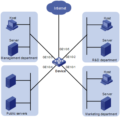
As shown in Figure 5, the enterprise network of a company interconnects all departments through Device. The network is described as follows:
· The marketing department connects to GigabitEthernet 1/0/1 of Device, which sets the 802.1p priority of traffic from the marketing department to 3.
· The R&D department connects to GigabitEthernet 1/0/2 of Device, which sets the 802.1p priority of traffic from the R&D department to 4.
· The management department connects to GigabitEthernet 1/0/3 of Device, which sets the 802.1p priority of traffic from the management department to 5.
Configure port priority and 802.1p-to-local mapping table to implement the plan as described in Table 1.
|
Traffic destination |
Traffic priority order |
Queuing plan |
||
|
Traffic source |
Output queue |
Queue priority |
||
|
Public servers |
R&D department > management department > marketing department |
R&D department |
6 |
High |
|
Management department |
4 |
Medium |
||
|
Marketing department |
2 |
Low |
||
Figure 3 Network diagram for priority mapping configuration
Configuration procedure
1. Configure trust port priority
# Set the port priority of GigabitEthernet 1/0/1 to 3.
<Device> system-view
[Device] interface gigabitethernet 1/0/1
[Device-GigabitEthernet1/0/1] qos priority 3
[Device-GigabitEthernet1/0/1] quit
# Set the port priority of GigabitEthernet 1/0/2 to 4.
[Device] interface gigabitethernet 1/0/2
[Device-GigabitEthernet1/0/2] qos priority 4
[Device-GigabitEthernet1/0/2] quit
# Set the port priority of GigabitEthernet 1/0/3 to 5.
[Device] interface gigabitethernet 1/0/3
[Device-GigabitEthernet1/0/3] qos priority 5
[Device-GigabitEthernet1/0/3] quit
2. Configure the priority mapping table
# Configure the 802.1p-to-local mapping table to map 802.1p priority values 3, 4, and 5 to local precedence values 2, 6, and 4. This guarantees the R&D department, management department, and marketing department decreased priorities to access the public server.
[Device] qos map-table dot1p-lp
[Device-maptbl-dot1p-lp] import 3 export 2
[Device-maptbl-dot1p-lp] import 4 export 6
[Device-maptbl-dot1p-lp] import 5 export 4
[Device-maptbl-dot1p-lp] quit
Primap configuration example
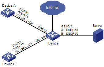
Network requirements
As shown in Figure 4, Device A is connected through its GigabitEthernet 1/0/1 port to Device C. The DSCP value of traffic sent out the port is 11. Device B is connected through its GigabitEthernet 1/0/2 port to Device C. The DSCP value of traffic sent out the port is 13.
Configure priority mapping to satisfy requirements 1 as follows:
· Mark packets from Device A with DSCP 50 and packets from Device B with DSCP 30.
· When Ethernet 1/3 of Device C is congested, Device C schedules the packets according to their priority prior to priority mapping, and allows Device B to preferentially access Server.
Configure priority mapping to satisfy requirements 2 as follows:
· Mark packets from Device A with DSCP 50 and packets from Device B with DSCP 30.
· When GigabitEthernet 1/0/3 of Device C is congested, Device C schedules the packets according to their priority after priority mapping, and allows Device A to preferentially access Server.
Figure 4 Network diagram for primap configuration
Configuration procedure
1. Configurations for requirements 1
# Configure the DSCP-to-DSCP mapping table.
<DeviceC> system-view
[DeviceC] qos map-table dscp-dscp
[DeviceC-maptbl-dscp-dscp] import 11 export 50
[DeviceC-maptbl-dscp-dscp] import 13 export 30
[DeviceC-maptbl-dscp-dscp] quit
# Create basic ACL 2001, and configure a rule to match packets with source IP address 192.168.0.1.
[DeviceC] acl number 2001
[DeviceC-acl-basic-2001] rule permit source 192.168.0.1 0
[DeviceC-acl-basic-2001] quit
# Create basic ACL 2002, and configure a rule to match packets with source IP address 192.168.0.2.
[DeviceC] acl number 2002
[DeviceC-acl-basic-2002] rule permit source 192.168.0.2 0
[DeviceC-acl-basic-2002] quit
# Create a class named classifier_devicea, and use basic ACL 2001 as the match criterion in the class.
[DeviceC] traffic classifier classifier_devicea
[DeviceC-classifier-classifier_devicea] if-match acl 2001
[DeviceC-classifier-classifier_devicea] quit
# Create a class named classifier_deviceb, and use basic ACL 2002 as the match criterion in the class.
[DeviceC] traffic classifier classifier_deviceb
[DeviceC-classifier-classifier_deviceb] if-match acl 2002
[DeviceC-classifier-classifier_deviceb] quit
# Create a behavior named behavior_devicea, and configure the primap action.
[DeviceC] traffic behavior behavior_devicea
[DeviceC-behavior-behavior_devicea] primap pre-defined dscp-dscp
[DeviceC-behavior-behavior_devicea] quit
# Create a behavior named behavior_deviceb, and configure the primap action.
[DeviceC] traffic behavior behavior_deviceb
[DeviceC-behavior-behavior_deviceb] primap pre-defined dscp-dscp
[DeviceC-behavior-behavior_deviceb] quit
# Create a policy named policy_server1, and associate the classes with the behaviors in the policy.
[DeviceC] qos policy policy_server1
[DeviceC-qospolicy-policy_server1] classifier classifier_devicea behavior behavior_devicea
[DeviceC-qospolicy-policy_server1] quit
# Create a policy named policy_server2, and associate the classes with the behaviors in the policy.
[DeviceC] qos policy policy_server2
[DeviceC-qospolicy-policy_server2] classifier classifier_deviceb behavior behavior_deviceb
[DeviceC-qospolicy-policy_server2] quit
# Apply the policy named policy_server1 to the incoming traffic of GigabitEthernet 1/0/1.
[DeviceC] interface gigabitethernet 1/0/1
[DeviceC-GigabitEthernet1/0/1] qos apply policy policy_server1 inbound
[DeviceC-GigabitEthernet1/0/1] quit
# Apply the policy named policy_server2 to the incoming traffic of GigabitEthernet 1/0/2.
[DeviceC] interface gigabitethernet 1/0/2
[DeviceC-GigabitEthernet1/0/2] qos apply policy policy_server2 inbound
Priority mapping table and priority marking configuration example
|
|
NOTE: For information about priority marking, see the chapter “Priority marking configuration.” |
Network requirements
As shown in Figure 5, the enterprise network of a company interconnects all departments through Device. The network is described as follows:
· The marketing department connects to GigabitEthernet 1/0/1 of Device, which sets the 802.1p priority of traffic from the marketing department to 3.
· The R&D department connects to GigabitEthernet 1/0/2 of Device, which sets the 802.1p priority of traffic from the R&D department to 4.
· The management department connects to GigabitEthernet 1/0/3 of Device, which sets the 802.1p priority of traffic from the management department to 5.
Configure port priority, 802.1p-to-local mapping table, and priority marking to implement the plan as described in Table 2.
|
Traffic destination |
Traffic priority order |
Queuing plan |
||
|
Traffic source |
Output queue |
Queue priority |
||
|
Public servers |
R&D department > management department > marketing department |
R&D department |
6 |
High |
|
Management department |
4 |
Medium |
||
|
Marketing department |
2 |
Low |
||
|
Internet |
Management department > marketing department > R&D department |
R&D department |
2 |
Low |
|
Management department |
6 |
High |
||
|
Marketing department |
4 |
Medium |
||
Figure 5 Network diagram for priority mapping table and priority marking configuration
Configuration procedure
1. Configure trusting port priority
# Set the port priority of GigabitEthernet 1/0/1 to 3.
<Device> system-view
[Device] interface gigabitethernet 1/0/1
[Device-GigabitEthernet1/0/1] qos priority 3
[Device-GigabitEthernet1/0/1] quit
# Set the port priority of GigabitEthernet 1/0/2 to 4.
[Device] interface gigabitethernet 1/0/2
[Device-GigabitEthernet1/0/2] qos priority 4
[Device-GigabitEthernet1/0/2] quit
# Set the port priority of GigabitEthernet 1/0/3 to 5.
[Device] interface gigabitethernet 1/0/3
[Device-GigabitEthernet1/0/3] qos priority 5
[Device-GigabitEthernet1/0/3] quit
2. Configure the priority mapping table
# Configure the 802.1p-to-local mapping table to map 802.1p priority values 3, 4, and 5 to local precedence values 2, 6, and 4.
[Device] qos map-table dot1p-lp
[Device-maptbl-dot1p-lp] import 3 export 2
[Device-maptbl-dot1p-lp] import 4 export 6
[Device-maptbl-dot1p-lp] import 5 export 4
[Device-maptbl-dot1p-lp] quit
3. Configure priority marking
Mark the HTTP packets from the management department, marketing department, and R&D department with 802.1p priority values 4, 5, and 3, respectively, which will be mapped to local precedence values 6, 4, and 2 according to the 802.1p-to-local mapping table configured above.
# Configure ACL 3000 to match HTTP packets.
[Device] acl number 3000
[Device-acl-adv-3000] rule permit tcp destination-port eq 80
[Device-acl-adv-3000] quit
# Create a class named http, and use ACL 3000 as the match criterion.
[Device] traffic classifier http
[Device-classifier-http] if-match acl 3000
[Device-classifier-http] quit
# Configure a QoS to mark the traffic from the management department with 802.1p priority 4, and apply the policy to the incoming traffic of the GigabitEthernet 1/0/3.
[Device] traffic behavior admin
[Device-behavior-admin] remark dot1p 4
[Device-behavior-admin] quit
[Device] qos policy admin
[Device-qospolicy-admin] classifier http behavior admin
[Device-qospolicy-admin] quit
[Device] interface gigabitethernet 1/0/3
[Device-GigabitEthernet1/0/3] qos apply policy admin inbound
# Configure a QoS to mark the traffic from the marketing department with 802.1p priority 5, and apply the policy to the incoming traffic of the GigabitEthernet 1/0/1.
[Device] traffic behavior market
[Device-behavior-market] remark dot1p 5
[Device-behavior-market] quit
[Device] qos policy market
[Device-qospolicy-market] classifier http behavior market
[Device-qospolicy-market] quit
[Device] interface gigabitethernet 1/0/1
[Device-GigabitEthernet1/0/1] qos apply policy market inbound
# Configure a QoS to mark the traffic from the R&D department with 802.1p priority 3, and apply the policy to the incoming traffic of the GigabitEthernet 1/0/2.
[Device] traffic behavior rd
[Device-behavior-rd] remark dot1p 3
[Device-behavior-rd] quit
[Device] qos policy rd
[Device-qospolicy-rd] classifier http behavior rd
[Device-qospolicy-rd] quit
[Device] interface gigabitethernet 1/0/2
[Device-GigabitEthernet1/0/2] qos apply policy rd inbound
Line rate configuration
This chapter includes these sections:
· Displaying and maintaining line rate
· Line rate configuration example
|
|
NOTE: · The term "switch" or "device" in this chapter refers to the switching engine on a WX3000E wired-wireless switch. · The WX3000E series comprises WX3024E and WX3010E wired-wireless switches. · The port numbers in this chapter are for illustration only. |
Line rate overview
|
|
NOTE: Line rate supports rate-limiting the inbound traffic and the outbound traffic. The outbound traffic is taken for example. |
The line rate of a physical interface specifies the maximum rate for forwarding packets (including critical packets).
Line rate also uses token buckets for traffic control. With line rate configured on an interface, all packets to be sent through the interface are handled by the token bucket at line rate. If enough tokens are in the token bucket, packets can be forwarded. Otherwise, packets are put into QoS queues for congestion management. In this way, the traffic passing the physical interface is controlled.
Figure 6 Line rate implementation
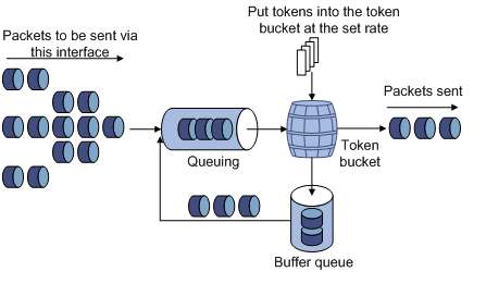
The token bucket mechanism limits traffic rate when accommodating bursts. It allows bursty traffic to be transmitted if enough tokens are available. If tokens are inadequate, packets cannot be transmitted until efficient tokens are generated in the token bucket. It restricts the traffic rate to the rate for generating tokens.
Line rate limits the total rate of all packets on a physical interface. It is easier to use than traffic policing in controlling the total traffic rate on a physical interface.
Configuring the line rate
The line rate of a physical interface specifies the maximum rate of incoming packets or outgoing packets.
Follow these steps to configure the line rate:
|
To do… |
Use the command… |
Remarks |
|
|
Enter system view |
system-view |
— |
|
|
Enter interface view or port group view |
Enter interface view |
interface interface-type interface-number |
Use either command. Settings in interface view take effect on the current interface. Settings in port group view take effect on all ports in the port group. |
|
Enter port group view |
port-group manual port-group-name |
||
|
Configure the line rate for the interface or port group |
qos lr { inbound | outbound } cir committed-information-rate |
Required |
|
Displaying and maintaining line rate
|
To do… |
Use the command… |
Remarks |
|
Display interface line rate configuration information |
display qos lr interface [ interface-type interface-number ] [ | { begin | exclude | include } regular-expression ] |
Available in any view |
Line rate configuration example
Configure line rate on GigabitEthernet 1/0/1 to limit the outgoing traffic rat to 1280 kbps.
# Enter system view.
<Sysname> system-view
# Enter interface view.
[Sysname] interface gigabitethernet 1/0/1
# Configure line rate on GigabitEthernet 1/0/1 to limit the outgoing traffic rat to 1280 kbps.
[Sysname-GigabitEthernet1/0/1] qos lr outbound cir 1280
Congestion management configuration
This chapter includes these sections:
· Congestion management overview
· Congestion management configuration approaches
|
|
NOTE: · The term "switch" or "device" in this chapter refers to the switching engine on a WX3000E wired-wireless switch. · The WX3000E series comprises WX3024E and WX3010E wired-wireless switches. · The port numbers in this chapter are for illustration only. |
Congestion management overview
Causes, impacts, and countermeasures
Network congestion degrades service quality on a traditional network. Congestion is a situation where the forwarding rate decreases due to insufficient resources, resulting in extra delay.
Congestion is more likely to occur in complex packet switching circumstances. Figure 7 shows two common cases:
Figure 7 Traffic congestion causes
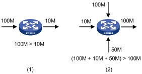
Congestion can bring the following negative results:
· Increased delay and jitter during packet transmission
· Decreased network throughput and resource use efficiency
· Network resource (memory in particular) exhaustion and even system breakdown
Congestion is unavoidable in switched networks and multi-user application environments. To improve the service performance of your network, you must take some proper measures to address the congestion issues.
The key to congestion management is how to define a dispatching policy for resources to decide the order of forwarding packets when congestion occurs.
Congestion management techniques
Congestion management uses queuing and scheduling algorithms to classify and sort traffic leaving a port. Each queuing algorithm addresses a particular network traffic problem, and has a different impact on bandwidth resource assignment, delay, and jitter. A port of the switching engine on a WX3000E wired-wireless switch provides four queues numbered 3, 2, 1, and 0, which accommodate the packets with local precedence values 6 and 7, 4 and 5, 2 and 3, and 0 and 1, respectively.
Queue scheduling processes packets by their priorities, preferentially forwarding high-priority packets. This section describes in detail Strict Priority (SP) queuing, Weighted Round Robin (WRR) queuing, and SP+WRR queuing.
SP queuing
SP queuing is designed for mission-critical applications, which require preferential service to reduce the response delay when congestion occurs.
Figure 8 Schematic diagram for SP queuing
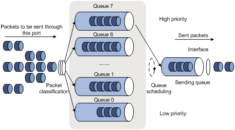
As shown in Figure 8, SP queuing classifies eight queues on a port into four classes, numbered 3 to 0 in descending priority order.
SP queuing schedules the eight queues in the descending order of priority. It sends packets in the queue with the highest priority first. When the queue with the highest priority is empty, it sends packets in the queue with the second highest priority, and so on. You can assign mission-critical packets to the high priority queue to ensure that they are always served first and common service packets to the low priority queues and transmitted when the high priority queues are empty.
The disadvantage of SP queuing is that packets in the lower priority queues cannot be transmitted if packets exist in the higher priority queues. This may cause lower priority traffic to starve to death.
WRR queuing
WRR queuing schedules all the queues in turn to ensure every queue is be served for a certain time, as shown in Figure 9.
Figure 9 Schematic diagram for WRR queuing
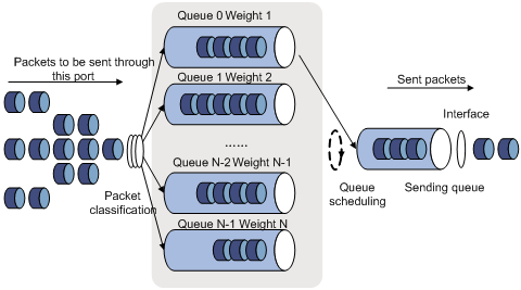
Assume a port provides four output queues. WRR assigns each queue a weight value (represented by w3, w2, w1, or w0) to decide the proportion of resources assigned to the queue. On a 100 Mbps port, you can configure the weight values of WRR queuing to 50, 30, 10, and 10 (corresponding to w3, w2, w1, and w0, respectively). In this way, the queue with the lowest priority can get a minimum of 20 Mbps of bandwidth. WRR avoids the disadvantage of SP queuing that packets in low-priority queues may fail to be served for a long time.
Another advantage of WRR queuing is that when the queues are scheduled in turn, the service time for each queue is not fixed. If a queue is empty, the next queue will be scheduled immediately. This improves bandwidth resource use efficiency.
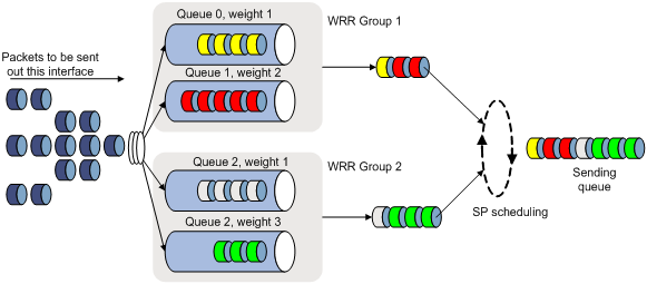
The switching engine on a WX3000E wired-wireless switch supports group-based WRR queuing. You can organize WRR queues into WRR scheduling groups 1 and 2. During queue scheduling, WRR is performed in each group, and then the dequeued packets are scheduled by using SP queuing.
Figure 10 Queue scheduling for the two WRR scheduling groups
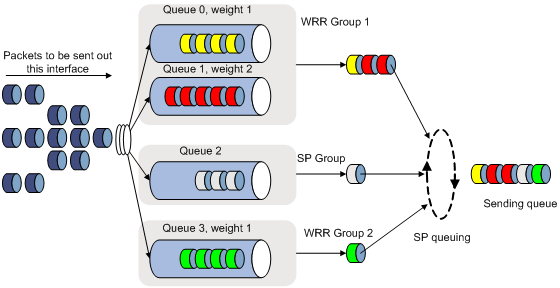
SP+WRR queuing
To implement SP+WRR queuing, assign some queues to the SP scheduling group, some to WRR scheduling group 1, and the others to WRR scheduling group 2. During queue scheduling, queues in each WRR scheduling group are scheduled by using WRR according to their weights, and then the dequeued packets together with the packets in the SP scheduling group are scheduled by using SP queuing.
For example, suppose you assign queues 0 and 1 to WRR scheduling group 1, with their weights 1 and 2, assign queue 3 to WRR scheduling group 2, with its weight 1, and assign queue 2 to the SP scheduling group. The scheduling process is as shown in Figure 11.
Figure 11 SP+WRR queuing
Congestion management configuration approaches
Complete the following tasks to achieve hardware congestion management:
|
Task |
Remarks |
|
Optional |
Congestion management
Configuring SP queuing
Configuration procedure
Follow these steps to configure SP queuing:
|
To do… |
Use the command… |
Remarks |
|
|
Enter system view |
system-view |
— |
|
|
Enter interface view or port group view |
Enter interface view |
interface interface-type interface-number |
Use either command. Settings in interface view take effect on the current interface. Settings in port group view take effect on all ports in the port group. |
|
Enter port group view |
port-group manual port-group-name |
||
|
Configure SP queuing |
undo qos wrr |
Required By default, an interface uses the SP queuing. |
|
Configuration example
1. Network requirements
Configure GigabitEthernet 1/0/1 to use SP queuing.
2. Configuration procedure
# Enter system view
<Sysname> system-view
# Configure GigabitEthernet1/0/1 to use SP queuing.
[Sysname] interface gigabitethernet 1/0/1
[Sysname-GigabitEthernet1/0/1] undo qos wrr
Configure WRR queuing
Configuration procedure
1. Configuring WRR queuing
Follow these steps to configure basic WRR queuing:
|
To do… |
Use the command… |
Remarks |
|
|
Enter system view |
system-view |
— |
|
|
Enter interface view or port group view |
Enter interface view |
interface interface-type interface-number |
Use either command. Settings in interface view take effect on the current interface. Settings in port group view take effect on all ports in the port group. |
|
Enter port group view |
port-group manual port-group-name |
||
|
Configure a basic WRR queue |
qos wrr queue-id group group-id weight schedule-value |
Required By default, an interface uses the SP queuing. |
|
|
Display WRR queuing configuration information on interfaces |
display qos wrr interface [ interface-type interface-number ] [ | { begin | exclude | include } regular-expression ] |
Optional Available in any view |
|
|
|
NOTE: · Support for queue scheduling types depends on your device model. · Interface types supporting queue scheduling profiles depends on your device model. · Only one queue scheduling profile can be applied to an interface. |
Configuration example
1. Network requirements
· Enable WRR queuing on interface GigabitEthernet 1/0/1.
· Assign queues 0 and 1 to WRR scheduling group 1, with the weight of 10 and 20, respectively.
· Assign queues 2 and 3 to WRR scheduling group 2, with the weight of 30 and 50, respectively.
2. Configuration procedure
# Enter system view.
<Sysname> system-view
# Configure WRR queuing on interface GigabitEthernet 1/0/1.
[Sysname] interface gigabitethernet 1/0/1
[Sysname-GigabitEthernet1/0/1] qos wrr 0 group 1 weight 10
[Sysname-GigabitEthernet1/0/1] qos wrr 1 group 1 weight 20
[Sysname-GigabitEthernet1/0/1] qos wrr 2 group 2 weight 30
[Sysname-GigabitEthernet1/0/1] qos wrr 3 group 2 weight 50
Configuring SP+WRR queuing
Configuration procedure
Follow these steps to configure basic SP+WRR queuing:
|
To do… |
Use the command… |
Remarks |
|
|
Enter system view |
system-view |
— |
|
|
Enter interface view or port group view |
Enter interface view |
interface interface-type interface-number |
Use either command. Settings in interface view take effect on the current interface. Settings in port group view take effect on all ports in the port group. |
|
Enter port group view |
port-group manual port-group-name |
||
|
Assign a queue to the SP scheduling group |
qos wrr queue-id group sp |
Required |
|
|
Assign a queue to the specified WRR scheduling group, and specify a weight for the queue |
qos wrr queue-id group group-id weight schedule-value |
Required |
|
|
|
NOTE: To guarantee that WRR queues are scheduled according to their weights, assign queues with continuous numbers to the same WRR scheduling group when configuring SP+WRR queuing. |
Configuration example
1. Network requirements
Configure SP+WRR queuing on interface GigabitEthernet 1/0/1 as follows:
· Assign queue 0 to the SP scheduling group.
· Assign queue 1 to WRR scheduling group 1, with the weight of 20.
· Assign queues 2 and 3 to WRR scheduling group 2, with the weight of 10 and 50.
2. Configuration procedure
# Enter system view.
<Sysname> system-view
# Configure SP+WRR queuing on interface GigabitEthernet 1/0/1.
[Sysname] interface gigabitethernet 1/0/1
[Sysname-GigabitEthernet1/0/1] qos wrr 0 group sp
[Sysname-GigabitEthernet1/0/1] qos wrr 1 group 1 weight 20
[Sysname-GigabitEthernet1/0/1] qos wrr 2 group 2 weight 10
[Sysname-GigabitEthernet1/0/1] qos wrr 3 group 2 weight 50
This chapter includes these sections:
· Configuring traffic filtering
· Traffic filtering configuration example
|
|
NOTE: · The term "switch" or "device" in this chapter refers to the switching engine on a WX3000E wired-wireless switch. · The WX3000E series comprises WX3024E and WX3010E wired-wireless switches. · The port numbers in this chapter are for illustration only. |
Traffic filtering overview
|
|
NOTE: You can apply an ACL to a port to implement traffic filtering. For more information, see the chapter “ACL configuration.” |
Configuring traffic filtering
Follow these steps to configure traffic filtering:
|
To do… |
Use the command… |
Remarks |
|
|
Enter system view |
system-view |
— |
|
|
Create a class and enter class view |
traffic classifier tcl-name [ operator { and | or } ] |
— |
|
|
Configure match criteria |
if-match match-criteria |
— |
|
|
Return to system view |
quit |
— |
|
|
Create a behavior and enter behavior view |
traffic behavior behavior-name |
— |
|
|
Configure the traffic filtering action |
filter { deny | permit } |
Required · deny: Drops packets. · permit: Permits packets to pass through. |
|
|
Return to system view |
quit |
— |
|
|
Create a policy and enter policy view |
qos policy policy-name |
— |
|
|
Associate the class with the traffic behavior in the QoS policy |
classifier tcl-name behavior behavior-name |
— |
|
|
Return to system view |
quit |
— |
|
|
Apply the QoS policy |
To an interface |
— |
|
|
To online users |
— |
||
|
To a VLAN |
— |
||
|
Globally |
— |
||
|
Display the traffic filtering configuration |
display traffic behavior user-defined [ behavior-name ] [ | { begin | exclude | include } regular-expression ] |
Optional Available in any view |
|
|
|
NOTE: With filter deny configured for a traffic behavior, the other actions (except class-based accounting) in the traffic behavior do not take effect. Whether traffic filtering can work with class-based accounting depends on your device model. |
Traffic filtering configuration example
Traffic filtering configuration example
Network requirements
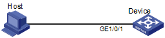
As shown in Figure 12, Host is connected to GigabitEthernet 1/0/1 of Device.
Figure 12 Network diagram for traffic filtering configuration
Configuration procedure
# Create advanced ACL 3000, and configure a rule to match packets whose source port number is 21.
<DeviceA> system-view
[DeviceA] acl number 3000
[DeviceA-acl-adv-3000] rule 0 permit tcp source-port eq 21
[DeviceA-acl-adv-3000] quit
# Create a class named classifier_1, and use ACL 3000 as the match criterion in the class.
[DeviceA] traffic classifier classifier_1
[DeviceA-classifier-classifier_1] if-match acl 3000
[DeviceA-classifier-classifier_1] quit
# Create a behavior named behavior_1, and configure the traffic filtering action to drop packets.
[DeviceA] traffic behavior behavior_1
[DeviceA-behavior-behavior_1] filter deny
[DeviceA-behavior-behavior_1] quit
# Create a policy named policy, and associate class classifier_1 with behavior behavior_1 in the policy.
[DeviceA] qos policy policy
[DeviceA-qospolicy-policy] classifier classifier_1 behavior behavior_1
[DeviceA-qospolicy-policy] quit
# Apply the policy named policy to the incoming traffic of GigabitEthernet 1/0/1.
[DeviceA] interface gigabitethernet 1/0/1
[DeviceA-GigabitEthernet1/0/1] qos apply policy policy inbound
This chapter includes these sections:
· Configuring priority marking
· Priority marking configuration example
|
|
NOTE: · The term "switch" or "device" in this chapter refers to the switching engine on a WX3000E wired-wireless switch. · The WX3000E series comprises WX3024E and WX3010E wired-wireless switches. · The port numbers in this chapter are for illustration only. |
Priority marking overview
|
|
NOTE: Priority marking can be used together with priority mapping. For more information, see the chapter “Priority mapping configuration.” |
Priority marking sets the priority fields or flag bits of packets to modify the priority of traffic. For example, you can use priority marking to set IP precedence or DSCP for a class of IP traffic to change its transmission priority in the network.
Configuring priority marking
Follow these steps to configure priority marking:
|
To do… |
Use the command… |
Remarks |
|
|
Enter system view |
system-view |
— |
|
|
Create a class and enter class view |
traffic classifier tcl-name [ operator { and | or } ] |
— |
|
|
Configure match criteria |
if-match match-criteria |
— |
|
|
Return to system view |
quit |
— |
|
|
Create a behavior and enter behavior view |
traffic behavior behavior-name |
— |
|
|
Set the DSCP value for packets |
remark dscp dscp-value |
Optional |
|
|
Set the 802.1p priority for packets or configure the inner-to-outer tag priority copying function |
remark dot1p 8021p |
Optional |
|
|
Set the IP precedence for packets |
remark ip-precedence ip-precedence-value |
Optional |
|
|
Set the local precedence for packets |
remark local-precedence local-precedence |
Optional |
|
|
Set the SVLAN ID for packets |
remark service-vlan-id vlan-id |
Optional |
|
|
Return to system view |
quit |
— |
|
|
Create a policy and enter policy view |
qos policy policy-name |
— |
|
|
Associate the class with the traffic behavior in the QoS policy |
classifier tcl-name behavior behavior-name |
— |
|
|
Return to system view |
quit |
— |
|
|
Apply the QoS policy |
To an interface |
— |
|
|
To online users |
— |
||
|
To a VLAN |
— |
||
|
Globally |
— |
||
|
Display the priority marking configuration |
display traffic behavior user-defined [ behavior-name ] [ | { begin | exclude | include } regular-expression ] |
Optional Available in any view |
|
Priority marking configuration example
Priority marking configuration example
Network requirements
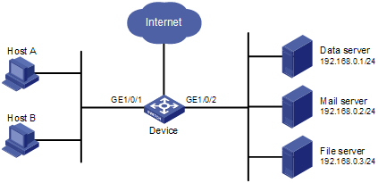
As shown in Figure 13, the enterprise network of a company interconnects hosts with servers through Device. The network is described as follows:
· Host A and Host B are connected to GigabitEthernet 1/0/1 of Device.
· The data server, mail server, and file server are connected to GigabitEthernet 1/0/2 of Device.
Configure priority marking on Device to satisfy the following requirements:
|
Traffic source |
Destination |
Processing priority |
|
Host A, B |
Data server |
High |
|
Host A, B |
Mail server |
Medium |
|
Host A, B |
File server |
Low |
Figure 13 Network diagram for priority marking configuration
Configuration procedure
# Create advanced ACL 3000, and configure a rule to match packets with destination IP address 192.168.0.1.
<Device> system-view
[Device] acl number 3000
[Device-acl-adv-3000] rule permit ip destination 192.168.0.1 0
[Device-acl-adv-3000] quit
# Create advanced ACL 3001, and configure a rule to match packets with destination IP address 192.168.0.2.
[Device] acl number 3001
[Device-acl-adv-3001] rule permit ip destination 192.168.0.2 0
[Device-acl-adv-3001] quit
# Create advanced ACL 3002, and configure a rule to match packets with destination IP address 192.168.0.3.
[Device] acl number 3002
[Device-acl-adv-3002] rule permit ip destination 192.168.0.3 0
[Device-acl-adv-3002] quit
# Create a class named classifier_dbserver, and use ACL 3000 as the match criterion in the class.
[Device] traffic classifier classifier_dbserver
[Device-classifier-classifier_dbserver] if-match acl 3000
[Device-classifier-classifier_dbserver] quit
# Create a class named classifier_mserver, and use ACL 3001 as the match criterion in the class.
[Device] traffic classifier classifier_mserver
[Device-classifier-classifier_mserver] if-match acl 3001
[Device-classifier-classifier_mserver] quit
# Create a class named classifier_fserver, and use ACL 3002 as the match criterion in the class.
[Device] traffic classifier classifier_fserver
[Device-classifier-classifier_fserver] if-match acl 3002
[Device-classifier-classifier_fserver] quit
# Create a behavior named behavior_dbserver, and configure the action of setting the local precedence value to 4.
[Device] traffic behavior behavior_dbserver
[Device-behavior-behavior_dbserver] remark local-precedence 4
[Device-behavior-behavior_dbserver] quit
# Create a behavior named behavior_mserver, and configure the action of setting the local precedence value to 3.
[Device] traffic behavior behavior_mserver
[Device-behavior-behavior_mserver] remark local-precedence 3
[Device-behavior-behavior_mserver] quit
# Create a behavior named behavior_fserver, and configure the action of setting the local precedence value to 2.
[Device] traffic behavior behavior_fserver
[Device-behavior-behavior_fserver] remark local-precedence 2
[Device-behavior-behavior_fserver] quit
# Create a policy named policy_server, and associate classes with behaviors in the policy.
[Device] qos policy policy_server
[Device-qospolicy-policy_server] classifier classifier_dbserver behavior behavior_dbserver
[Device-qospolicy-policy_server] classifier classifier_mserver behavior behavior_mserver
[Device-qospolicy-policy_server] classifier classifier_fserver behavior behavior_fserver
[Device-qospolicy-policy_server] quit
# Apply the policy named policy_server to the incoming traffic of GigabitEthernet 1/0/1.
[Device] interface gigabitethernet 1/0/1
[Device-GigabitEthernet1/0/1] qos apply policy policy_server inbound
[Device-GigabitEthernet1/0/1] quit
Traffic redirecting configuration
This chapter includes these sections:
· Traffic redirecting overview
· Configuring traffic redirecting
|
|
NOTE: · The term "switch" or "device" in this chapter refers to the switching engine on a WX3000E wired-wireless switch. · The WX3000E series comprises WX3024E and WX3010E wired-wireless switches. · The port numbers in this chapter are for illustration only. |
Traffic redirecting overview
Traffic redirecting is the action of redirecting the packets matching the specific match criteria to a certain location for processing.
The switching engine on a WX3000E wired-wireless switch supports redirecting traffic to an interface. When the switch receives packets to be processed by a specific interface, you can configure redirecting traffic to the interface. Traffic redirecting applies to only Layer 2 packets.
Configuring traffic redirecting
Follow these steps to configure traffic redirecting:
|
To do… |
Use the command… |
Remarks |
|
|
Enter system view |
system-view |
— |
|
|
Create a class and enter class view |
traffic classifier tcl-name [ operator { and | or } ] |
— |
|
|
Configure match criteria |
if-match match-criteria |
— |
|
|
Return to system view |
quit |
— |
|
|
Create a behavior and enter behavior view |
traffic behavior behavior-name |
Required |
|
|
Configure a traffic redirecting action |
redirect interface interface-type interface-number |
Optional You can specify the traffic redirecting destination as needed. |
|
|
Return to system view |
quit |
— |
|
|
Create a policy and enter policy view |
qos policy policy-name |
— |
|
|
Associate the class with the traffic behavior in the QoS policy |
classifier tcl-name behavior behavior-name |
— |
|
|
Return to system view |
quit |
— |
|
|
Apply the QoS policy |
To an interface |
— |
|
|
To a VLAN |
— |
||
|
Globally |
— |
||
Burst configuration
This chapter includes these sections:
|
|
NOTE: · The term "switch" or "device" in this chapter refers to the switching engine on a WX3000E wired-wireless switch. · The WX3000E series comprises WX3024E and WX3010E wired-wireless switches. · The port numbers in this chapter are for illustration only. |
Burst overview
The burst function improves packet buffering and forwarding performance in the following scenarios:
· Dense broadcast or multicast traffic and massive burst traffic are present.
· High-speed traffic is forwarded over a low-speed link or traffic received from multiple interfaces at the same speed is forwarded through an interface at the same speed.
By enabling the burst function on your device, you can improve the processing performance of the device operating in these scenarios to reduce packet loss.
Make sure that you are fully aware of the impacts when enabling the burst function, because the burst function may affect the QoS performance of your device.
Configuring burst
Configuration prerequisites
Make sure that the burst function is necessary for addressing your problem.
Configuration procedure
Follow these steps to enable the burst function:
|
To do… |
Use the command… |
Remarks |
|
Enter system view |
system-view |
— |
|
Enable the burst function |
burst-mode enable |
Required Disabled by default. |
Burst configuration example
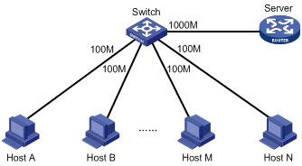
Network requirements
In the customer network shown in Figure 14, a server connects to the switch through a 1000 Mbps Ethernet interface. The server sends dense broadcast or multicast traffic to the hosts irregularly. Each host connects to the switch through a 100 Mbps network adapter.
Configure the switch to process dense traffic from the server to guarantee that packets can reach the hosts.
Figure 14 Network diagram for burst configuration
Configuration procedure
# Enter system view.
<Switch> system-view
# Enable the burst function.
[Switch] burst-mode enable
This chapter includes these sections:
· Appendix A Default priority mapping tables
· Appendix B Introduction to packet precedences
|
|
NOTE: · The term "switch" or "device" in this chapter refers to the switching engine on a WX3000E wired-wireless switch. · The WX3000E series comprises WX3024E and WX3010E wired-wireless switches. · The port numbers in this chapter are for illustration only. |
Appendix A Default priority mapping tables
Uncolored priority mapping tables
|
|
NOTE: For the default dot1p-dot1p and dscp-dscp priority mapping tables, an input value yields a target value equal to it. |
Table 3 Default dot1p-lp and dot1p-dscp priority mapping tables
|
Input priority value |
dot1p-lp mapping |
dot1p-dscp mapping |
|
802.1p priority (dot1p) |
Local precedence (lp) |
dscp |
|
0 |
2 |
0 |
|
1 |
0 |
8 |
|
2 |
1 |
16 |
|
3 |
3 |
24 |
|
4 |
4 |
32 |
|
5 |
5 |
40 |
|
6 |
6 |
48 |
|
7 |
7 |
56 |
Table 4 Default dscp-lp, dscp-dp, dscp-dot1p, and dscp-exp priority mapping tables
|
Input priority value |
dscp-lp mapping |
dscp-dot1p mapping |
|
DSCP |
Local precedence (lp) |
802.1p priority (dot1p) |
|
0 to 7 |
0 |
0 |
|
8 to 15 |
1 |
1 |
|
16 to 23 |
2 |
2 |
|
24 to 31 |
3 |
3 |
|
32 to 39 |
4 |
4 |
|
40 to 47 |
5 |
5 |
|
48 to 55 |
6 |
6 |
|
56 to 63 |
7 |
7 |
Appendix B Introduction to packet precedences
IP precedence and DSCP values

As shown in Figure 15, the ToS field in the IP header contains eight bits. The first three bits (0 to 2) represent IP precedence from 0 to 7. According to RFC 2474, the ToS field is redefined as the differentiated services (DS) field, where a DSCP value is represented by the first six bits (0 to 5) and is in the range 0 to 63. The remaining two bits (6 and 7) are reserved.
Table 5 Description on IP precedence
|
IP precedence (decimal) |
IP precedence (binary) |
Description |
|
0 |
000 |
Routine |
|
1 |
001 |
priority |
|
2 |
010 |
immediate |
|
3 |
011 |
flash |
|
4 |
100 |
flash-override |
|
5 |
101 |
critical |
|
6 |
110 |
internet |
|
7 |
111 |
network |
Table 6 Description on DSCP values
|
DSCP value (decimal) |
DSCP value (binary) |
Description |
|
46 |
101110 |
ef |
|
10 |
001010 |
af11 |
|
12 |
001100 |
af12 |
|
14 |
001110 |
af13 |
|
18 |
010010 |
af21 |
|
20 |
010100 |
af22 |
|
22 |
010110 |
af23 |
|
26 |
011010 |
af31 |
|
28 |
011100 |
af32 |
|
30 |
011110 |
af33 |
|
34 |
100010 |
af41 |
|
36 |
100100 |
af42 |
|
38 |
100110 |
af43 |
|
8 |
001000 |
cs1 |
|
16 |
010000 |
cs2 |
|
24 |
011000 |
cs3 |
|
32 |
100000 |
cs4 |
|
40 |
101000 |
cs5 |
|
48 |
110000 |
cs6 |
|
56 |
111000 |
cs7 |
|
0 |
000000 |
be (default) |
802.1p priority
802.1p priority lies in the Layer 2 header and applies to occasions where Layer 3 header analysis is not needed and QoS must be assured at Layer 2.
Figure 16 An Ethernet frame with an 802.1Q tag header
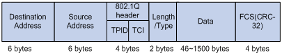
As shown in Figure 16, the four-byte 802.1Q tag header consists of the tag protocol identifier (TPID, two bytes in length), whose value is 0x8100, and the tag control information (TCI, two bytes in length). Figure 17 presents the format of the 802.1Q tag header. The Priority field in the 802.1Q tag header is called the “802.1p priority”, because its use is defined in IEEE 802.1p. Table 7 presents the values for 802.1p priority.
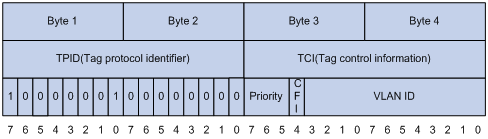
Table 7 Description on 802.1p priority
|
802.1p priority (decimal) |
802.1p priority (binary) |
Description |
|
0 |
000 |
best-effort |
|
1 |
001 |
background |
|
2 |
010 |
spare |
|
3 |
011 |
excellent-effort |
|
4 |
100 |
controlled-load |
|
5 |
101 |
video |
|
6 |
110 |
voice |
|
7 |
111 |
network-management |
